Abstract
This study presents a systematic investigation on the thermal power characteristics of linear conjugate internal gear pumps. Through analyzing the heat sources of each friction pair in the internal gear pump, mathematical heat generation models for key friction pairs are derived based on mechanical efficiency and volumetric efficiency. Furthermore, the simulation model of the gear pump was established, and the losses of the internal gear pump under different working conditions were calculated and analyzed. The variation patterns of mechanical efficiency and volumetric efficiency under different pressures and speeds are studied, revealing significant declines in both efficiencies under complex operating conditions, with inefficiencies primarily occurring under low-speed high-pressure and high-speed low-pressure scenarios. The results show that the deviation between the simulation results of mechanical efficiency and the experimental value is less than 1.6%, and the deviation between the simulation results of volumetric efficiency and the experimental value is less than 1%. Variations in speed and pressure significantly impact both mechanical and volumetric efficiencies, with notable efficiency drops observed under low-speed/high-pressure conditions. In high-pressure environments, intensified radial unbalanced forces lead to increased frictional heat generation.
1. Introduction
The linear conjugate internal gear pump has been widely adopted in industries such as injection molding machines, machine tools, and agricultural equipment due to its compact structure, small footprint, excellent sealing performance, low noise characteristics, and minimal flow pulsation [,,,,,]. However, this pump demonstrates less than 75% efficiency under low-speed, high-pressure conditions and below 80% efficiency at high speeds. Under low-speed operating conditions, insufficient lubrication in friction pairs leads to increased heat generation, while under high-speed conditions, viscous friction losses in rotating components surge significantly, resulting in severe thermal accumulation. This excessive temperature rise may induce lubrication failure and accelerated wear, ultimately limiting component performance [].
Thermal power characteristics represent one of the core parameters in the design and performance evaluation of hydraulic power components, holding significant research value, particularly for critical power elements such as hydraulic pumps [,,]. When hydraulic systems operate under high-speed and high-pressure conditions, the heat generated by mechanical friction, volumetric losses, and fluid viscous shear significantly affects the operational efficiency and reliability of components [,,,].
Firstly, as the core component of energy conversion, the non-uniform temperature distribution within hydraulic pumps may induce thermal fatigue of materials, seal aging, and viscosity degradation of the hydraulic oil, consequently leading to reduction in volumetric efficiency and increased vibration and noise [,,]. Secondly, the accumulation and dissipation characteristics of thermal power directly affect the system’s energy balance, where improper thermal management strategies would exacerbate energy waste and shorten the service life of components [,,].
The research objects of hydraulic pump thermal characteristics are mainly plunger pump and external gear pump. Grandall D investigated hydraulic pump efficiency from the perspectives of volumetric efficiency and mechanical efficiency, establishing a mathematical model and deriving theoretical calculation formulas []. Wang S studied the heat generation and heat transfer mechanism of the hydraulic pump, established the thermodynamic model of the hydraulic pump by using the control volume method, and accurately predicted the temperature change caused by pump leakage and friction []. Iboshi, N and Yamaguchi, A, aiming at the mixed lubrication characteristics of slipper pair of piston pump, revealed the evolution law of power loss of friction pair with the increase in speed by establishing average flow model and random rough contact theory []. Through ANSYS (v.2021) static simulation, Dong Jicheng et al. revealed the mechanical characteristics of the cylinder–disc friction pair of the radial piston pump with disc flow distribution under the condition of 40 °C and accurately located the concentration area of equivalent stress and the extreme value area of thermal deformation under two rotation modes []. Chang Liang investigated the temperature rise effect of high-power-density 2D piston pumps. Through thermal–hydraulic coupling modeling, experimental tests and Ansys transient thermal simulation, he revealed the distribution law of thermal losses in the transmission system and verified the consistency between the thermal model below 4000 rpm and the formula for stirring losses []. Rituraj R studied the influence of fluid temperature change on the performance of external gear pump, proposed a lumped parameter based thermal model, revealed the limitations of isothermal assumption in inefficient conditions, and clarified the temperature gradient distribution of fluid in the pumping process []. Sujan, D proposed a fluid–solid–thermal coupling model for axial lubrication clearance of external meshing gear machinery, which for the first time integrated the thermoelastic lubrication effect and solid thermoelastic deformation mechanism and proposed a fluid mechanical efficiency evaluation model for external meshing gear machinery []. Zardin, B quantified the tooth tip, side clearance, journal bearing, and meshing losses of an external meshing gear pump through numerical analysis of the gap geometry and pressure distribution and revealed the dominant roles of side clearance and meshing losses under low pressure conditions, as well as their dynamic response patterns with respect to rotational speed and viscosity []. The dynamic simulation model of linear conjugate gear pump is established and verified by orthogonal experiment. Chai H established a dynamic simulation model of linear conjugate internal gear pump and used orthogonal experiments to demonstrate that the oil content, oil temperature, and working pressure have a significant impact on the total efficiency [].
However, current research exhibits notable limitations: existing thermodynamic studies on external gear pumps also inadequately support the optimization requirements of internal gear architectures. Quantitative descriptions of friction pair power loss under high-speed conditions remain insufficient. Additionally, the influence of external operating conditions such as rotational speed and pressure on thermal equilibrium remains inadequately clarified.
In this study, the thermal efficiency of conjugate linear internal gear pump is analyzed. A systematic investigation into the heat generation mechanism is carried out, focusing on the power loss mechanisms of friction pairs. Numerical heat generation models are established for key friction pairs, including the gear and ring gear, gear shaft and crescent plate, sliding bearings, and end faces, with an in-depth analysis of their volumetric and mechanical loss mechanisms. Subsequently, a Simulink-based simulation model is developed to analyze the numerical models. The results indicate that mechanical and volumetric losses increase significantly at lower rotational speeds, while mechanical efficiency and volumetric efficiency improve under high-pressure conditions, the inefficiency mainly occurs in the two operating conditions of “low speed high pressure” and “high speed low pressure”. Finally, volumetric efficiency, mechanical efficiency, and housing temperature are tested under different operating conditions on a linear conjugate internal gear pump test rig, experimentally validating the simulation results, and the deviation between the simulation and the experiment is less than 1.6% at high speed. This study establishes a numerical model for heat generation in internal gear pumps, accompanied by analysis and experimental validation, laying a research foundation for future reduction in gear power loss.
2. Model of Friction by Heat Produced by Internal Gear Pump
The linear conjugate internal gear pump operates as a strictly fixed-clearance hydraulic device, where the rotational motion of the driving gear induces ring gear movement, with pressure isolation maintained through a stationary crescent plate. The thermal generation mechanisms in this pump primarily stem from three sources: volumetric losses due to fluid leakage, viscous dissipation in the working fluid, and mechanical friction losses at solid–solid contact interfaces.
The volumetric losses caused by leakage consist of six components as depicted in Figure 1. These include A is leakage from the high-pressure outlet to the suction port through the clearance between the crescent plate and the ring gear, B is leakage through the gap between the crescent plate and the gear, C is leakage via the axial clearance between the gear and the housing end face, D is leakage through the axial clearance between the ring gear and the housing end face, E is leakage across the meshing clearance between the gear and the ring gear, as well as F is leakage through the radial annular gap between the ring gear and the housing. The composition of this leakage flow is complex, primarily consisting of the flow supplied by the hydrostatic support ports and the flow of high-pressure fluid passing through the axial end face of the ring gear.
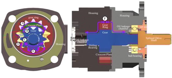
Figure 1.
Schematic diagram of volume loss tracing of internal gear pump.
The mechanical loss caused by friction mainly consists of 7 parts as shown in Figure 2. 1 is friction loss between gearring and crescent plate, 2 is radial ring clearance friction loss between gear ring and shell, 3 is friction loss between gear and crescent plate, 4 is sliding bearing friction loss between gear shaft and shell, 5 is sealing friction loss between gear ring end face and shell, 6 is sealing friction loss between gear end face and shell, 7 is mechanical loss caused by fixed rolling bearing installed on gear shaft.
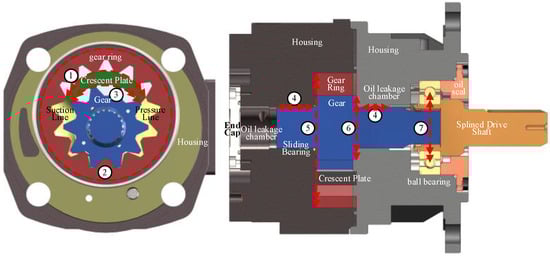
Figure 2.
Schematic diagram of mechanical loss tracing of internal gear pump.
In order to make a clear and in-depth analysis of the heat generation mechanism, we trace the heat generation mechanism in the form of power loss generated by the moving friction pair.
2.1. Source Analysis of Heat Generation in the Ring Gear-Housing Radial Tribological Pair
During the rotation of the gear ring, the pressure generated by the high-pressure liquid, the meshing force of the gear and gear ring transmission, and the sum of the extrusion force generated by the forced movement are in the eccentric motion state relative to the annular space of the shell. At the same time, in order to compensate for the negative effect caused by the radial unbalanced force, the static pressure support notch is usually opened on the shell, and its mechanism is similar to that of the dynamic and static pressure lubricating bearing []. The oil film model of ring interface friction pair of gear ring shell is shown in Figure 3.
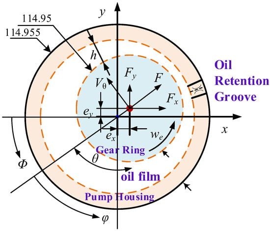
Figure 3.
Oil film model of annular interface friction pair of gear ring housing.
The friction pair at the ring gear-housing interface is analogous to that of a bearing journal. By referencing the rotational frictional resistance and leakage flow characteristics of bearing journals, the mechanical losses and volumetric losses at the sliding interface between the ring gear and housing can be quantitatively determined. The friction force and mechanical loss of the sliding friction pair at the annular interface of the gear ring housing are expressed by Equations (1) and (2):
where is the ring gear thickness; is the ring gear radius; is the oil film thickness; is coefficient of viscosity; is the hydrodynamic film pressure; is the ring gear peripheral velocity.
The total leakage flow and total volumetric loss at the interface of the gear ring housing are can be calculated using Equations (3) and (4), as follows:
where is the hydrostatic support groove pressure; is the radius of the hydrostatic support groove; D is the inner diameter of the housing; c is correction factor; is the dynamic eccentricity; is angular coordinates of hydrostatic support groove; is the difference pressure between hydrostatic bearing groove and oil suction port; c is correction factor.
2.2. Source Analysis of Heat Generation in the Radial Friction Pair Between Gear Ring and Housing
The clearance between the gear/ring and the crescent plate plays the role of high-pressure oil seal and oil suction and drainage port transport, and its leakage direction is opposite to the rotation direction. However, in actual operation, only a few sealing lines are used for sealing, which leads to a sudden increase in leakage flow at low speed. Conversely, the thin-walled oil film in the gap during high-speed rotation suppresses the leakage but increases the friction loss []. The motion of the friction pair between the gear/ring and the crescent plate is shown in Figure 4.
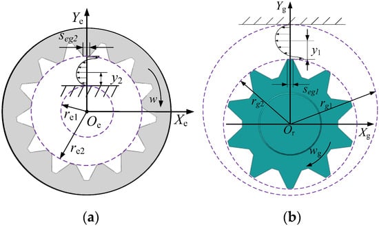
Figure 4.
Oil film sketch: (a) between gear ring and crescent plate moving friction pair; (b) between gear and crescent plate moving friction pair.
The velocity of oil movement in the clearance between gear and crescent plate under different operating conditions can be governed by Equation (5):
where is the number of gear teeth involved in sealing; is the tooth tip thickness of the gear; is the dynamic viscosity of the hydraulic oil; is the arbitrary distance between the gear tooth tip and the crescent plate; is the linear velocity at the gear tooth tip; is the inner radius of the crescent plate; is the pressure difference between the suction and discharge ports; is the radius of the gear tooth tip.
Equations (6) and (7) describe the leakage flow and volumetric loss between the gear and the friction pair of the crescent plate.
The frictional loss between gear and friction pair of crescent plate can be expressed by Equation (8):
The velocity of oil movement in the gap between the tooth ring and the crescent plate under different operating conditions can be expressed by Equation (9):
where is the number of teeth of ring teeth involved in sealing; is the thickness of gear tip; is arbitrary distance between ring tooth tip and crescent plate; is the linear velocity at the gear ring tooth tip; is the outer radius of tooth plate; is the radius of the gear ring tooth tip.
The volumetric loss between the gear ring and the friction pair of the crescent plate is expressed by Equation (10), as follows:
The frictional loss between the gear ring and the friction pair of the crescent plate be governed by Equation (11):
2.3. Source Analysis of Heat Generation in the Friction Pair Between the Rotating Shaft System and Crescent Plate
The gear shaft of linear conjugate internal meshing gear pump is supported by deep groove ball bearings, and both ends of the sliding friction pair formed by the journal and the wear-resistant bearing sleeve. As shown in Figure 5. The friction heat generation source consists of two parts: the rolling friction of the bearing and the contact friction of the sliding pair.
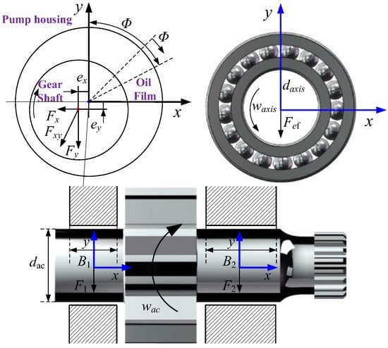
Figure 5.
Thermal analysis diagram of plain bearing and rolling bearing.
The frictional loss of deep groove ball bearing can be calculated using Equation (12), as follows:
where is speed of bearing rotation; is the coefficient of friction of the bearing; is the external load applied to the bearing; is the inner diameter of the bearing.
The frictional loss of the gear shaft sliding can be expressed by Equation (13), as follows:
where is upper sliding bearing length; is lower sliding bearing length.
2.4. Heat Generation Source Analysis of Axial End-Face Tribopair in Rotaing Shaft System
The end face friction pair formed by the end face of the gear ring/gear and the shell of the linear conjugate internal meshing gear pump can be modeled as a sloped flow of parallel rotating disks, and the total leakage flow is formed under the joint action of pressure flow and shear flow. In the four-quadrant condition, the direction of pressure flow leakage and shear flow leakage should be determined according to the operating quadrant.
The leakage flow of the end friction pair can be expressed by Equation (14):
where is the end surface oil film thickness; is the envelope Angle of the high pressure cavity of the outer gear, is the envelope Angle of the high pressure cavity of the inner gear ring; is the envelope Angle of the transition cavity of the outer gear; is the envelope Angle of the transition cavity of the inner gear ring; is the radius of the root circle of the outer gear; is the radius of the root circle of the inner gear ring; is the radius of the outer wall of the inner gear ring; is the radius of the inner wall of the outer gear.
The volumetric loss of the end face friction pair is expressed by Equation (15):
The mechanical loss of the end face friction pair is expressed by Equation (16):
where is the rotation angular velocity of the external gear.
3. Simulation of Thermal Power Characteristics
3.1. Simulation Model
To thoroughly investigate the energy dissipation mechanisms in linear conjugate internal gear pumps, a simulation model for analyzing mechanical and volumetric losses was developed based on the MATLAB/Simulink(2024b) platform, with the simulation framework illustrated in Figure 6. The precise calibration of geometric dimension parameters played a critical role in the simulation modeling process. As shown in Table 1 the dimensional and geometric parameters in the table are measured by the German Zeiss coordinate measuring instrument, and the measuring accuracy is 1 micron.
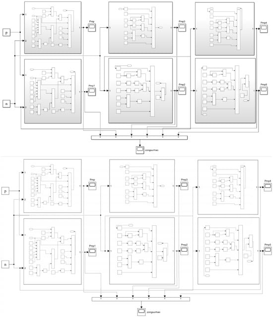
Figure 6.
Matlab/Simulink power loss simulation model.

Table 1.
Heat tracing simulation parameter table of internal gear pump.
3.2. Simulation Results and Analysis
3.2.1. Simulation Analysis of Mechanical Losses Under Rated Operating Conditions
As shown in Figure 7, the mechanical losses of the internal gear pump exhibit positive correlations with both rotational speed and pressure yet demonstrate significantly higher sensitivity to speed variations compared to pressure. Under a constant speed of 2000 r/min, the mechanical losses increased by 0.69 kW as the pressure rose from 0 to 21 MPa. Conversely, at a constant pressure of 21 MPa, the mechanical losses escalated by 0.92 kW when the rotational speed increased from 0 to 2000 r/min. Comparative analysis with piston pumps revealed distinct mechanical loss characteristics: piston pumps exhibit reduced mechanical losses under high-pressure conditions due to improved lubrication in friction pairs, whereas gear pumps show continuous mechanical loss growth with increasing pressure. This phenomenon is primarily attributed to the deteriorated lubrication and intensified frictional heating at the ring housing annular interface caused by amplified radial unbalanced forces. These findings conclusively identify rotational speed variation as the dominant factor influencing mechanical losses.
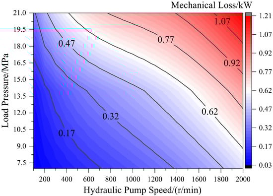
Figure 7.
Mechanical loss distribution cloud map of internal gear pump.
3.2.2. Volumetric Loss Analysis Under Rated Operating Conditions
As depicted in Figure 8, the volumetric losses of internal gear pumps exhibit positive correlations with both rotational speed and pressure yet demonstrate substantially higher sensitivity to speed variations compared to pressure fluctuations. Under constant-speed operation at 2000 r/min, the volumetric losses increase by 1.19 kW as pressure escalates from 0 MPa to 21 MPa. Conversely, under constant pressure conditions at 21 MPa, the volumetric losses show a 0.68 kW increment when rotational speed rises from 0 to 2000 r/min.
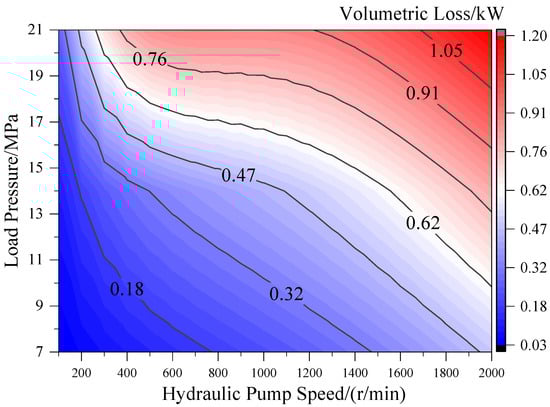
Figure 8.
Volumetric loss distribution cloud diagram of internal gear pump.
3.2.3. Power Loss Analysis at Extreme High Speed
As shown in Figure 9, internal gear pumps exhibit two distinct low-efficiency zones. In the low-speed high-pressure zone, insufficient hydrodynamic film load capacity in friction pairs and weakened velocity sealing effects lead to a reduction in volumetric efficiency. Conversely, the high-speed low-pressure zone suffers from deteriorated mechanical efficiency due to sharp growth in frictional power consumption of moving components and degradation of lubrication performance. The study demonstrates that at the rated speed of 2000 r/min, pressure elevation from 7 MPa to 21 MPa dominates total loss modulation with a 1.37 kW increase, while speed variation between 500 r/min and 2000 r/min induces a weaker influence of only 0.899 kW increment. Notably, under extreme high-speed conditions at 3500 r/min, rotational speed sensitivity surpasses pressure effects: accelerating from 2000 r/min to 3500 r/min at constant 21 MPa results in a 1.99 kW loss surge, significantly exceeding the 1.529 kW increase caused by pressure elevation from 7 MPa to 21 MPa. It can be obtained that the power loss under the extremely high speed condition is more sensitive to the speed change.
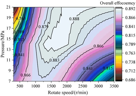
Figure 9.
Internal gear pump total efficiency distribution cloud.
4. Experimental Verification
4.1. Experimental Scheme
To verify the accuracy of the above summarized simulation model, a comprehensive performance test bed for linear conjugate internal gear pump was constructed, as shown in Figure 10. It uses servo motor direct drive structure, built-in speed torque sensor to monitor input parameters in real time and sets the flow rate and pressure difference sensor in series at the inlet and outlet, respectively. The proportional valve loading system is used to simulate working conditions, and the auxiliary oil filling system is used to provide 2–3 bar oil suction pressure. The layout of the test bench is shown in Figure 10a, Composition of the piping system of the test bench is shown in Figure 10b, Composition of the electrical system of the test bench is shown in Figure 10c. The experimental system of power loss and thermal balance is shown in Figure 11, which integrates surface-mounted temperature sensor and shell opening oil film pressure detection module and uses a thermal imager to obtain the temperature field distribution of the shell under different working conditions. Flow sensors, speed torque sensors, pressure and other sensor data are connected to the controller through the expansion module, and the upper configuration software is used to record and store the data. The key sensor technical parameters are shown in Table 2.
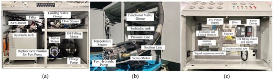
Figure 10.
Comprehensive performance testing test bench for internal gear pumps. (a) Layout of the test bench; (b) Composition of the piping system of the test bench; (c) Composition of the electrical system of the test bench.
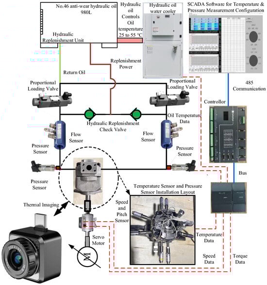
Figure 11.
Introduction to the experimental testing plan for power loss and thermal balance.
Table 2.
Power loss and thermal balance temperature experimental testing sensor parameter.
The power loss and efficiency test data of the hydraulic pump are calculated based on the following equations:
The total efficiency of hydraulic pump is the product of volumetric efficiency and mechanical efficiency:
4.2. Experimental Results and Analysis
For comparative analysis, as shown in Figure 12, three characteristic pressure conditions—7 MPa, 14 MPa, and 21 MPa—were selected. At the speed of 300 r/min, the difference between the simulated and experimental values of 7 MPa mechanical efficiency is 0.88%, the difference between the simulated and experimental values of 14 MPa mechanical efficiency is 1.18%, and the difference between the simulated and experimental values of 21 MPa mechanical efficiency is 5.11%. Mechanical efficiency demonstrates a declining trend across all pressure levels as rotational speed increases from 600 r/min to 3500 r/min. Notably, under 21 MPa conditions, mechanical efficiency paradoxically increases when rotational speed drops below 500 r/min. This phenomenon arises from amplified gear ring eccentricity under high pressure, which reduces the minimum oil film thickness between the gear ring and housing. Furthermore, diminished hydrodynamic lubrication effects at low speeds intensify friction at the gear ring housing interface, resulting in pronounced discrepancies between simulated and experimental mechanical efficiency values.
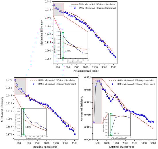
Figure 12.
Experimental validation of mechanical efficiency under all operating conditions.
As pressure increases, the discrepancy between simulation and experimental results gradually widens under low-speed conditions; while rising rotational speed enhances hydrodynamic lubrication effects in the oil film, reducing gear ring displacement and significantly improving mechanical efficiency. When operating at rotational speeds exceeding 600 r/min, the maximum discrepancy between simulated and experimental mechanical efficiency remained within 1.6% across all tested pressures, validating the accuracy of the mechanical loss model.
As evidenced by Figure 13, the experimental volumetric efficiency exhibits a characteristic “steep initial increase followed by gradual growth” trend when rotational speed rises from 300 r/min to 3500 r/min under varying pressures. A similar trend was observed for mechanical efficiency. At 300 r/min, the deviations between simulated and experimental volumetric efficiencies measured 0.83% at 7 MPa, 1.45% at 14 MPa, and 2.95% at 21 MPa. When the rotational speed is lower than 600 r/min, the simulation results of volumetric efficiency show significant discrepancies from the experimental results, and the greater the rotational speed, the larger the difference. This is due to the large eccentric movement of the gear ring under the speed operation condition, and the sealing clearance of the gear ring shell interface becomes larger, resulting in increased leakage. On the other hand, at low speed, the axial end face leakage direction of the gear ring is opposite to the speed direction, which also results in increased leakage. Higher rotational speeds enhanced hydrodynamic lubrication effects, reducing gear ring deflection and sealing clearance while improving sealing performance. At rotational speeds surpassing 600 r/min, the discrepancy between simulation outputs and empirical measurements was constrained within a 1% tolerance threshold under multi-stage pressure conditions of 7 MPa, 14 MPa, and 21 MPa, which systematically validated the predictive accuracy of the leakage dissipation model.
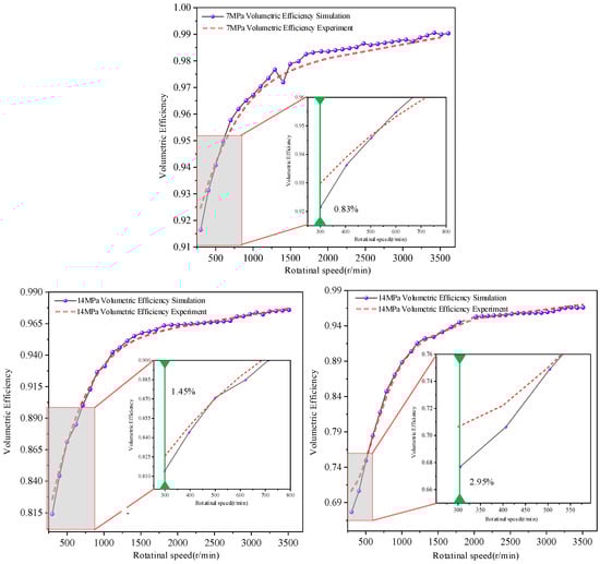
Figure 13.
Experimental validation of volumetric efficiency under all operating conditions.
Figure 14 shows the experimental total efficiency contour map of the internal gear pump under full operating conditions. The efficiency distribution reveals that two distinct low-efficiency zones predominantly exist: (1) a low-speed/high-pressure zone (0–800 r/min, 16–22 MPa) where efficiency drops to approximately 70–75%, primarily due to insufficient hydrodynamic film load capacity and weakened velocity sealing effects resulting in volumetric losses; and (2) a high-speed/low-pressure zone (3200–4000 r/min, 7–10 MPa) where efficiency decreases to around 75–80%, mainly caused by increased frictional power consumption and degraded lubrication performance. These experimental findings validate our simulation results presented in Section 3.2.3 and are further supported by the mechanical efficiency and volumetric efficiency comparisons shown in Figure 12 and Figure 13. The close agreement between simulated and experimental values for both mechanical efficiency (deviation < 1.6%) and volumetric efficiency (deviation < 1%) at high speeds confirms the reliability of our thermal power characteristics model for internal gear pumps across various operating conditions.
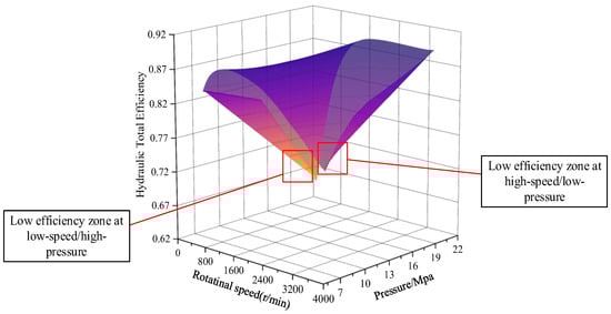
Figure 14.
Experimental validation of overall efficiency under all operating conditions.
5. Conclusions
This study conducted a systematic analysis of the thermal efficiency of linear conjugate internal gear pumps. The heat generation mechanisms were clarified, and numerical loss models for key friction pairs within the gear pump were developed.
Based on the mathematical model, the simulation model of internal gear pump is built in Simulink. Simulation demonstrated that both mechanical loss and volumetric loss increase with the increase in rotational speed and pressure. Moreover, the mechanical loss is more sensitive to rotational speed. The inefficiency mainly occurs in the two operating conditions of “low speed and high pressure” and “high speed and low pressure”. At high speed, the deviation between the simulated and experimental values of mechanical efficiency was less than 1.6%, and the deviation between the simulated and experimental values of volumetric efficiency was less than 1%. The experiments further revealed that mechanical efficiency and volumetric efficiency demonstrate decreasing trends with rising rotational speed, while significant efficiency deterioration occurs under low-speed/high-pressure conditions. This phenomenon primarily originated from insufficient hydrodynamic effects in lubricant films and exacerbated eccentricity of ring gears.
Future research should focus on both refining the simulation model and expanding its application scope. A comprehensive investigation of ring gear eccentricity effects on the friction pair’s tribological behavior will provide fundamental insights for optimizing gear pump performance.
Author Contributions
Conceptualization, B.Y. and C.Y.; Methodology, T.Z.; Software, K.L.; Validation, J.C. and H.Z.; Formal analysis, K.L.; Investigation, T.Z.; Data curation, G.C.; Writing—original draft, C.Y. and J.C.; Writing—review and editing, B.Y.; Visualization, H.Z. and F.W.; Project administration, F.W.; Funding acquisition, G.C. All authors have read and agreed to the published version of the manuscript.
Funding
This research was funded by Key Laboratory of Xinjiang Coal Resources Green Mining, Ministry of Education, Xinjiang Institute of Engineering (KLXGY-Z2402), Hebei Provincial Science and Technology Major Special Project (23281901Z), National Natural Science Foundation of China (52275066), Autonomous Region Colleges and Universities Research Program (XJEDU2024P087), ‘Tianchi Talent’ Introduction Programme (2024XGYTCYC02), Key Research and Development Program Project of the Autonomous Region (2024B01005-2).
Institutional Review Board Statement
Not applicable.
Informed Consent Statement
Not applicable.
Data Availability Statement
The original contributions presented in the study are included in the article, further inquiries can be directed to the corresponding author.
Conflicts of Interest
The authors declare no conflicts of interest.
References
- Tang, Y.; Lu, H.; Zhu, Z.C.; Shi, Z.Y.; Xu, B.L. Performance reliability evaluation of high-pressure internal gear pump. Qual. Reliab. Eng. Int. 2024, 40, 3465–3486. [Google Scholar] [CrossRef]
- Chen, Z.B.; Lin, H.; Jian, L. Design and Analysis of Conjugated Straight-Line Internal Gear Pairs. Int. J. Precis. Eng. Manuf. 2021, 22, 1425–1440. [Google Scholar] [CrossRef]
- Liao, J.; Zheng, J.B.; Chen, Z.B. Research on the Fault Diagnosis Method of an Internal Gear Pump Based on a Convolutional Auto-Encoder and PSO-LSSVM. Sensors 2022, 22, 9841. [Google Scholar] [CrossRef]
- Liu, Y.Y.; An, K.; Liu, H.; Gong, J.G.; Wang, L.Q. Numerical and experimental studies on flow performances and hydraulic radial forces of an internal gear pump with a high pressure. Eng. Appl. Comput. Fluid Mech. 2019, 13, 1130–1143. [Google Scholar] [CrossRef]
- Ivanović, L.; Stojanovic, B.; Blagojevic, J.; Bogdanovic, G.; Marinković, A. Analysis of the Flow Rate and the Volumetric Efficiency of the Trochoidal Pump by Application of Taguchi Method. Available online: https://scidar.kg.ac.rs/handle/123456789/8762 (accessed on 10 April 2025).
- Nguyen, D.-D.; Dang, D.-V.; Nguyen, M.-K.; Trinh, V.-H. Effects of adjustable and control parameters on performance characteristics of multi-controlled variable displacement pump. Appl. Eng. Lett. 2025, 10, 14–24. [Google Scholar] [CrossRef]
- Ye, S.; Lin, Q.; Zheng, C.; Zhao, S.; Liu, H. Dynamic modeling and vibration response analysis of an internal gear pump. Proc. Inst. Mech. Eng. Part C J. Mech. Eng. Sci. 2025, 8, 2823–2840. [Google Scholar] [CrossRef]
- Yang, C.; Yu, L.J.; Zhang, J.H.; Qian, J.Y. Cooling Performance Analysis of Outside Fins of the Closed Circuit Axial Piston Transmission. Machines 2021, 9, 17. [Google Scholar] [CrossRef]
- Wu, D.; Wang, S.; Shi, J. Thermal modeling of axial piston pump and application. In Proceedings of the 2015 International Conference on Fluid Power and Mechatronics (FPM), Harbin, China, 5–7 August 2015. [Google Scholar] [CrossRef]
- Li, K.; Lv, Z.; Lu, K.; Yu, P. Thermal-hydraulic Modeling and Simulation of the Hydraulic System Based on the Electro-Hydrostatic Actuator. In Proceedings of the 3rd International Symposium on Aircraft Airworthiness (ISAA), Toulouse, France, 19–21 November 2013; pp. 272–281. [Google Scholar]
- Li, D.; Dong, S.; Wang, J.; Li, Y. State-of-the-art and some considerations on thermal load analysis and thermal management for hydraulic system in MEA. J. Eng. 2018, 2018, 399–405. [Google Scholar] [CrossRef]
- Li, S.N.; Yang, P.; Zhao, R.; Liang, T.; Zhou, Z.Y. Theoretical and Experimental Research on Temperature Rise Mechanism of Oil in the Sealed Cavity of Intra-Vane Type Pump. Processes 2022, 10, 446. [Google Scholar] [CrossRef]
- Chang, L.; Li, Z.W.; Jia, W.N.; Li, S.; Ruan, J. Convective heat transfer of the Taylor flow in a two-dimensional piston pump. PLoS ONE 2022, 17, e0275897. [Google Scholar] [CrossRef]
- Yan, G.S.; Jin, Z.L.; Yang, M.K.; Yao, B. The Thermal Balance Temperature Field of the Electro-Hydraulic Servo Pump Control System. Energies 2021, 14, 1364. [Google Scholar] [CrossRef]
- Becker, K.M.; Kaye, J. Measurements of Diabatic Flow in an Annulus with an Inner Rotating Cylinder. J. Heat Transf. 1962, 84, 97–104. [Google Scholar] [CrossRef]
- Chao, Q.; Zhang, J.H.; Xu, B.; Huang, H.P.; Pan, M. A Review of High-Speed Electro-Hydrostatic Actuator Pumps in Aerospace Applications: Challenges and Solutions. J. Mech. Des. 2019, 141, 050801. [Google Scholar] [CrossRef]
- Liu, Y.S.; Li, D.L.; Tang, Z.Y.; Deng, Y.P.; Wu, D.F. Thermodynamic modeling, simulation and experiments of a water hydraulic piston pump in water hydraulic variable ballast system. Ocean Eng. 2017, 138, 35–44. [Google Scholar] [CrossRef]
- Kazama, T. Comparison of temperature measurements and thermal characteristics of hydraulic piston, vane, and gear pumps. Mech. Eng. J. 2015, 2, 14–00542. [Google Scholar] [CrossRef][Green Version]
- Zhang, X.; Wu, H.Y.; Chen, C.C.; Wang, D.Y.; Li, S.H. Oil film lubrication state analysis of piston pair in piston pump based on coupling characteristics of the fluid thermal structure. Eng. Fail. Anal. 2022, 140, 106521. [Google Scholar] [CrossRef]
- Li, C.-G.; Jiao, Z.-X. Thermal-hydraulic Modeling and Simulation of Piston Pump. Chin. J. Aeronaut. 2006, 19, 354–358. [Google Scholar] [CrossRef]
- Grandall, D.R. The Performance and Efficiency of Hydraulic Pumps and Motors. Ph.D. Thesis, University of Minnesota, Minneapolis, MN, USA, 2010. [Google Scholar]
- Iboshi, N.; Yamaguchi, A. Characteristics of a Slipper Bearing for Swash Plate Type Axial Piston Pumps and Motors: 1st Report, Theoretical Analysis. Bull. JSME 1982, 25, 1921–1930. [Google Scholar] [CrossRef][Green Version]
- Dong, J.-C.; Cao, W.-B.; Yang, G.-L.; Chen, C.; Gao, W.-T. Static Analysis of Key Friction Pair for High-pressure Large-displacement Valve Plate Radial Piston Pump. Hydraul. Pneum. Seals 2018, 38, 11–14. [Google Scholar]
- Rituraj, R.; Vacca, A.; Rigosi, M. Modeling and validation of hydro-mechanical losses in pressure compensated external gear machines. Mech. Mach. Theory 2021, 161, 104310. [Google Scholar] [CrossRef]
- Dhar, S.; Vacca, A. A fluid structure interaction-EHD model of the lubricating gaps in external gear machines: Formulation and validation. Tribol. Int. 2013, 62, 78–90. [Google Scholar] [CrossRef]
- Zardin, B.; Natali, E.; Borghi, M. Evaluation of the Hydro-Mechanical Efficiency of External Gear Pumps. Energies 2019, 12, 2468. [Google Scholar] [CrossRef]
- Chai, H.Q.; Yang, G.L.; Wu, G.G.; Bai, G.X.; Cao, C.C. Analysis of straight conjugate internal gear pump through numerical modeling and experimental validation. PLoS ONE 2022, 17, e0270979. [Google Scholar] [CrossRef] [PubMed]
- Bouchehit, B.; Benyebka, B.S.; Mathieu, G. Static and dynamic performances of refrigerant-lubricated bearings. Tribol. Int. 2016, 96, 326–348. [Google Scholar] [CrossRef]
- Mucchi, E.; Giorgio, D.; Fernandez, D.R. Elastodynamic analysis of a gear pump. Part I: Pressure distribution and gear eccentricity. Mech. Syst. Signal Process. 2010, 24, 2160–2179. [Google Scholar] [CrossRef]


Disclaimer/Publisher’s Note: The statements, opinions and data contained in all publications are solely those of the individual author(s) and contributor(s) and not of MDPI and/or the editor(s). MDPI and/or the editor(s) disclaim responsibility for any injury to people or property resulting from any ideas, methods, instructions or products referred to in the content. |
© 2025 by the authors. Licensee MDPI, Basel, Switzerland. This article is an open access article distributed under the terms and conditions of the Creative Commons Attribution (CC BY) license (https://creativecommons.org/licenses/by/4.0/).