Article

I-BIM Applied in Railway Geometric Inspection Activity: Diagnostic and Alert

1
Department of Civil Engineering, Architecture and Environment, Higher Technical Institute, University of Lisbon, 1049-001 Lisbon, Portugal
2
CERIS—Civil Engineering Research and Innovation for Sustainability, 1049-001 Lisbon, Portugal
*
Author to whom correspondence should be addressed.
Appl. Sci. 2025, 15(10), 5733; https://doi.org/10.3390/app15105733
Submission received: 15 April 2025 / Revised: 16 May 2025 / Accepted: 17 May 2025 / Published: 20 May 2025
(This article belongs to the Special Issue Building Information Modelling: From Theories to Practices)

Abstract

:
The Building Information Modeling (BIM) concept has been recently implemented in railway infrastructure, assisting mainly in the project elaboration, and further, the facility management aspect. The present study addresses the inspection activity of the railway geometry, in a BIM context, using a rigorous modeling process of the railway track components, and the development of a Dynamo script for the evaluation of the degree of geometric irregularity detected during inspection works. The monitoring phase of the rail tracks involves a planned railway inspection schedule, normally supported by human analyses of data collected in a railway geometric inspection. The created script allows for evaluating the inspection data and categorizes the data by alert levels that are associated with a color code, visualized over the railway components of the BIM model. The Dynamo script uses new BIM parameters considering the maintenance activity, allowing for analyzing inspection data and visualizing the colored alerts. This capacity alerts the maintenance engineer about the urgency of planning a retrofitting action, according to the severity level of the detected geometric anomaly. An illustrative real railway track segment is considered supporting the modeling process, the inspection data collection and the efficiency analyses of the script application. This research intends to contribute to increment knowledge of BIM adoption in railway infrastructures, emphasizing the potential of using Dynamo programming on BIM model database management.

1. Introduction

Building Information Modeling (BIM) methodology is currently applied in the construction domain, with a growing spread across different domains of the sector, revealing an evident recognition of the benefits achieved with its implementation [1]. The basic concept consists of the digital representation of a three-dimensional (3D) BIM virtual model, using the selection, adjustment and definition of parametric objects, to produce an accurate digital representation in a 3D shape and with physical properties [2]. This primary notion has been overtaken by the strategy of manipulating the model database for different types of tasks, such as construction planning (4D BIM model) or facility management (7D BIM model) [3,4,5]. In distinct sectors, and by observing the enormous potential of the BIM model database, there has been a strong trend to develop add-ins, plug-ins and extensions, associated to BIM software, and, more recently, the elaboration of specific scripts making use of Dynamo 3.3 (2025) or Python 3.13.3 (2025) programming languages [6,7,8].
The most recent developed scripts essentially consider the manipulation and generation of new data with the aim of adding value to BIM models, generated for each building or infrastructure project. In the present work, a Dynamo script was developed, allowing an increase in the BIM model ability with the insertion of the inspection’s railway data, the evaluation of the information related to geometric anomalies detected over the railway track components and the association of a color code correlated to the severity of the identified geometric inaccuracies [9].
Regarding the implementation of BIM in the railway project and maintenance, the available technical literature presents only a few scientific reports and publications; however, this topic, along with the different domains of the construction industry, has recently perceived a strong improvement in the real potential application of BIM. There is currently widespread interest in applying BIM methodology in a large spectrum of areas, from the design of bridges [10] to the preservation of heritage buildings [11]. This evident technological advance is driven by government directives that bet on BIM to establish a growing degree of digital transformation in construction [12].
While the term BIM is fundamentally applied to the building sector, the term Infrastructure Building Information Modeling (I-BIM) denotes the projects related to transport infrastructures [13]. The generation of I-BIM models, concerning railway infrastructure, requires the definition of new specific parametric objects representing the railway track components, as the availability of software libraries with objects of infrastructure components is limited, and the creation of new objects assigned to specific parameters is a time-consuming effort. The present research is oriented to analyze the I-BIM methodology implementation focused on railway inspection activity.
Currently, the significant use of the train, as a preferred means of transport, has led to an increased level of infrastructure degradation and a necessity for more maintenance actions, followed by the necessary restitution of the required capacity of the railway network. The level of the service quality of the railway infrastructure has begun to deteriorate, as a consequence of the material degradation of its components, caused fundamentally by the circulation of the trains, but also by the track’s exposure to the natural environment [14]. Railway enterprises must keep the train rails in good condition for the safety of the passengers, as badly damaged rails can cause not just service delays but catastrophic accidents. The anomalies found in the railway infrastructure frequently cause serious vibrations, and have the potential to cause accidents, putting the lives of the train passengers in danger.
The rail inspection activity includes the practice of examining rail tracks for faults that could lead to disastrous failures, as track defects can originate accidents on railways [15]. The materials applied on the railway’s components, mainly, rails, sleepers, fastenings and ballasts need inspection at frequent intervals [16]. The maintenance of the high quality, adequate efficiency and long-lasting functionality of the railway transport infrastructure requires a well-planned periodic inspection of the railway track components. Therefore, it is essential to establish regular inspections and collect data that constitute the key to analyzing the state of conservation of the railway components.
Important ongoing efforts have been made in the sector of railway track modeling of material deterioration to analyze the service life of the infrastructure and avoid failures of the component [17]. In addition, some recent studies involving BIM and Dynamo in a rail context can be mentioned. Wu et al. [18] investigated the use of the unmanned aerial vehicle for the measurement of the track gauge, as a distinct inspection procedure when compared with traditional methods, supported in a pre-built rail BIM model matched with the extracted rail features. Ferreno et al. [19] studied the mechanical properties, which depend on the service conditions, secondary to estimating with accuracy the mechanical behaviors of the rails that are positioned between the rails and the sleepers, minimizing the transmission of vibrations and noise. Chellaswamy et al. [20] presented a proposal to check geometric defects in railway tracks based on the use of a Dynamo script for identifying defects in railway tracks. Zhang et al. [21] investigated the detection of rail cracks based on the gathering optimization of features, by verifying the alerts that are identified in the environment of the railway. Chakraborty et al. [22] presented a study concerning the derailment aspect that can result in high death tolls or the loss of property, proposing a system to understand the communication between the train and rail track in real-time. Neves et al. [23] analyzed the BIM implementation in railway infrastructures focused on railway track rehabilitation activity.
The efficient management, processing and generation of inspection data require the use of computational tools with the capacity for facilitating decision-making regarding the efforts around the maintenance, rehabilitation or modernization of railways. It is the case of the present study focused on the implementation of BIM through the inspection of diagnostic and the alert activity [9]. In this study, a working research methodology was proposed referring to the related literature, the BIM modeling process and the development of a Dynamo script and its application and evaluation.

2. Materials and Methods

The study followed a work methodology composed of three main sequential steps aiming to reach relevant and useful conclusions for the I-BIM community regarding the railway infrastructure sector, with a focus on the inspection activity (Figure 1).
  • BIM modeling process: The first stage refers to the BIM modeling process in order to conceive of an accurate representation of the infrastructure it analyzed. A BIM model is a comprehensive 3D digital representation of the infrastructure, imposing a high demand on geometric and semantic data. The railway track components were mainly related to rails, fastenings, sleepers and layers of ballast. The available BIM modeling software did not contain libraries of parametric objects related to the railway infrastructure. As such, the geometry, the material and the related position of the components were carefully analyzed, based on the literature. This bibliographic access supported the generation of the required new parametric objects, accurate geometry and physical proprieties of the associated materials. Although the advanced modeling systems lead to advantages well highlighted by practice, in the case of transportation infrastructure, a time-consuming effort was required in this step. A new set of parametric objects were then generated, allowing the creation of BIM models of railway infrastructure.
  • Railway inspection activity: Next, the railway inspection activity was deeply studied, referring to the identification of the most frequent geometric irregularities and to the traditional inspection practices, considering mechanical, manual and semi-automatic processes. The railway track elements are susceptible to degradation caused by vehicle circulation characteristics (frequency of use, vehicle speed and volume of transported cargo), environmental aspects, infrastructure stability and the fact that the track is supported on a ballast layer subject to displacements in horizontal and vertical directions [24]. Infrequent or inadequate rail inspection plans can provoke negative consequences, and as such, a careful planning schedule of periodic inspections must be well defined and applied. During the inspection process, information about track conditions is collected, recorded and analyzed, and then recommendations can be made, and maintenance actions can be completed. Some of the parameters generally measured in a railway inspection include position, curvature, alignment of the track, smoothness and the cross level of the two rails. Through the utilization of track evaluation equipment, it is possible to determine the values of these parameters and compare them to the safety standards. In this way, it is possible to verify the presence and identification of anomalies, determine their causes and perform the needed repairs. As a case study, an illustrative segment of a real railway track was considered, supporting not just the modelling process, but also the collection of data inspection and the evaluation of the Dynamo script efficiency.
  • Dynamo script development: With the aim of introducing BIM as an innovative contribution to railway infrastructure, and in order to contribute to improving the general digital transformation of the construction industry, a new approach was considered based on Dynamo programming. A Dynamo script was developed allowing users to insert the collected inspection data into the 3D BIM model, and to handle the database supporting the geometric incurrences evaluation and the emission of alerts regarding the level of severity of the detected anomalies. The script allowed for the analysis of the geometric railway inspections’ data, its application over the real case study and the emission of an alert visualized over the model components. Several aspects were considered, namely, the process of inserting data into the BIM model, the association of a new inspection parameter with the objects, the classification of the detected degradation level and the identification of the degree of alert associated with a color code, allowing users to be aware of the state of conservation of the infrastructure in the analyses.

3. BIM Modeling Process

The adoption of the BIM methodology offers improved solutions when facing the current increasing demand from the industry and the challenges of achieving adequate resources to support the development of complex projects. A BIM project is supported on the centralization of information related to design, construction and maintenance, requiring as a first step the generation of a realistic digital BIM model of the building or infrastructure.
In the context of railway engineering, the present study intended to contribute to disseminate and clarify the principal improvements that BIM can introduce to the workflow efficiency within the railway inspection task. This topic remains underdeveloped and not widely applied in engineering practice. Therefore, a practical illustrative extension of a real case was selected, provided by the National Agency of Railway Infrastructure of Portugal [25]. All components needed to represent a railway track straight segment were created as new parametric objects.

3.1. Main Railway Track Components

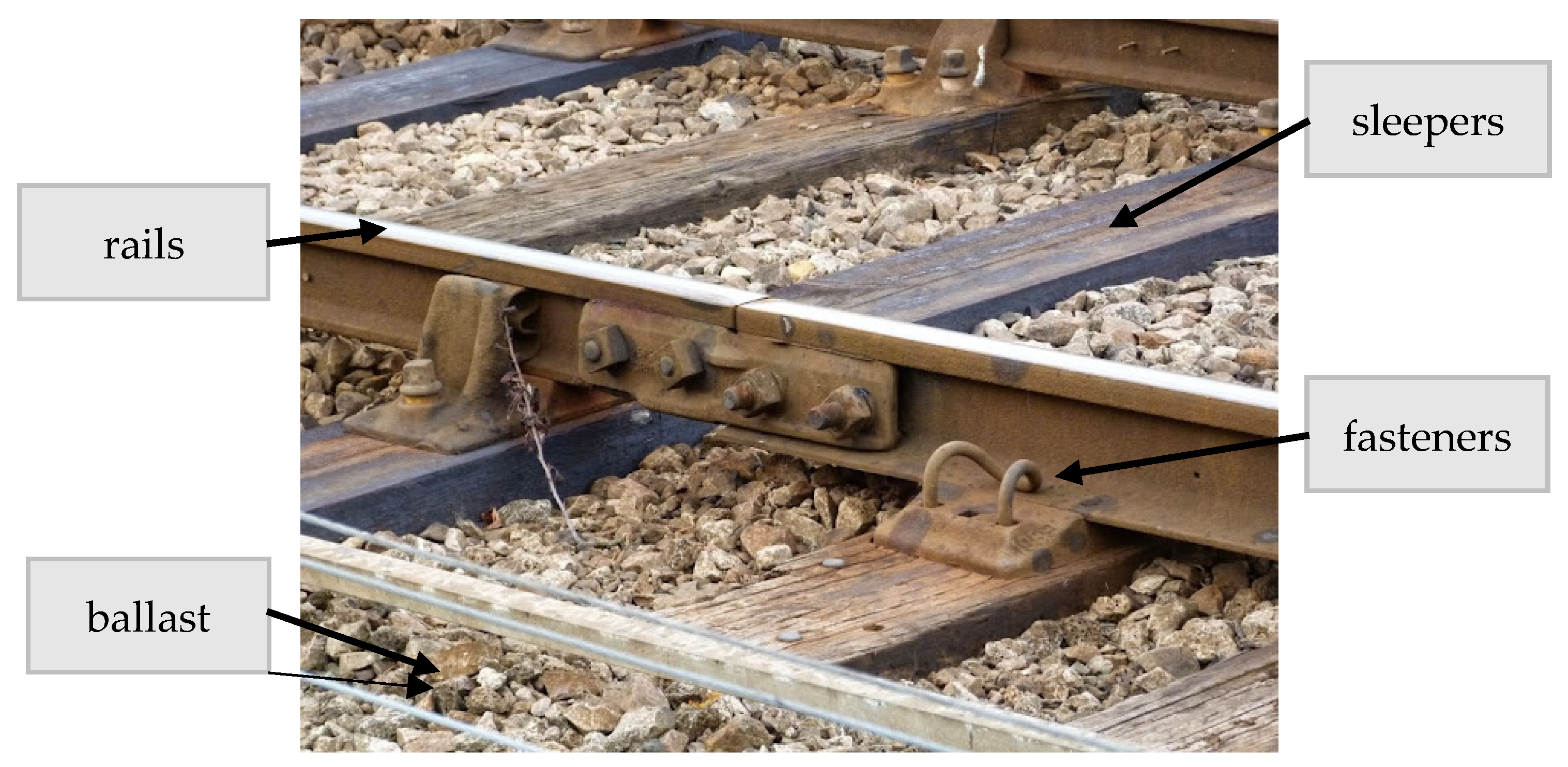
The superstructure of a railway is the component that directly impacts the loads transported, and it is composed of rails, fasteners, sleepers and layers of ballast and sub-ballast (Figure 2).
The European Committee for Standardization (Comité European de Normalization, CEN), which supports the emission of rules for Europe, the European Standards (ENs), established the document EN 13848:2022. This standard provides guidelines for the identification of the main rail track geometry factors, establishes the fundamental requirements to make the measurements and refers to the traditional inspection procedures, in order to ensure quality and safety on railway tracks [26]:
  • Rail track geometry components: a set of parameters considered in the description of the geometrical characteristics of the rail elements, namely, track gauge, longitudinal level, alignment, cross level and twist.
  • Track geometry quality: the valuation of the geometric deviation impact, in elevation and cross direction, considering the standard geometrical characteristics of each geometric parameter relevant to supporting the necessary safety concerning the drive quality.
  • Gauge: the measurement made between the inside faces of the ride rail track head.
  • Running table: the top surface of the rail.
  • Running surface: the bent surface identified by the longitudinal displacement of a straight rail segment orthogonal to the middle line of the rail track and the peripheral running sides.

3.2. Railway Track BIM Model

Revit (Autodesk) [27] was the BIM modeling software applied for the generation of the model of a railway track segment of the selected case study, based on the documents provided by the National Agency of Railway Infrastructure of Portugal [25]. The BIM model was created with the components required for the geometric inspection activity. As such, just the sleepers, fasteners and rails were modeled, forming a streamlined and efficient basis for conducting the required geometric inspections. This simplified approach allowed for a more targeted examination of the railway track’s structure, supporting the BIM implementation analyses in the railway sector.
Revit is a parametric modeling system requiring the use of parametric objects representative of the construction components. The system contains libraries of parametric objects’ families associated with a 3D digital representation and a set of fetchers related to shape, size, materials and behavior. Considering the generation of the simplified railway model, no adequate parametric families were found within the software library or in the related web pages. In order to overcome this problem, new families of objects were created, concerning the sleepers, fastenings and rail track elements.

3.2.1. Sleepers and Fastening Families

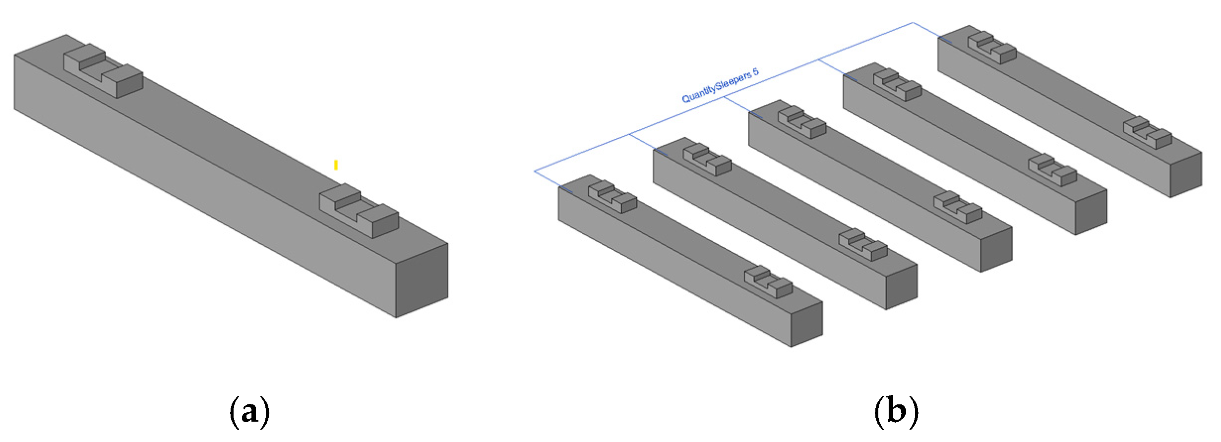
The Revit system allows users to create new families of parametric objects. The sleeper family definition was based on a single solid block with dimensions 2600 × 300 × 270 mm3. Complementing a sleeper, two fastenings were then considered. For that, a new family of objects was created as the fastening element. This rail component was then duplicated and placed over the sleeper (Figure 3a). The complete first element was then replicated forming an array established with 600 mm spacing between sleepers (Figure 3b). The material associated with the new objects was concrete.

3.2.2. Rail Track Family

Another family of objects was created considering the rail track modeling. In order to later support the association of the inspection data, the rail was considered, composed of segments 25 cm long. Following the reading process of measures adopted by the National Guide, the EM120 inspection vehicle, the inspection data were collected every 25 cm along the rail.
For the creation of a rail segment presenting a constant cross-section, the section shape was first defined, based on the standard EN 13848:2022, and after, an extrusion geometric operation was applied along the longitudinal axe, defining a rail segment 25 cm long (Figure 4a). The modeled element was replicated, positioned in parallel and a distance between them of 1668 mm was observed. This value corresponded to the Iberian gauge that was adopted by the Portuguese railway’s entity (Figure 4b). The twin elements were then copied, using an array function, forming the required extension (Figure 4c). The material associated with the new parametric object was steel.

3.2.3. Composed Model

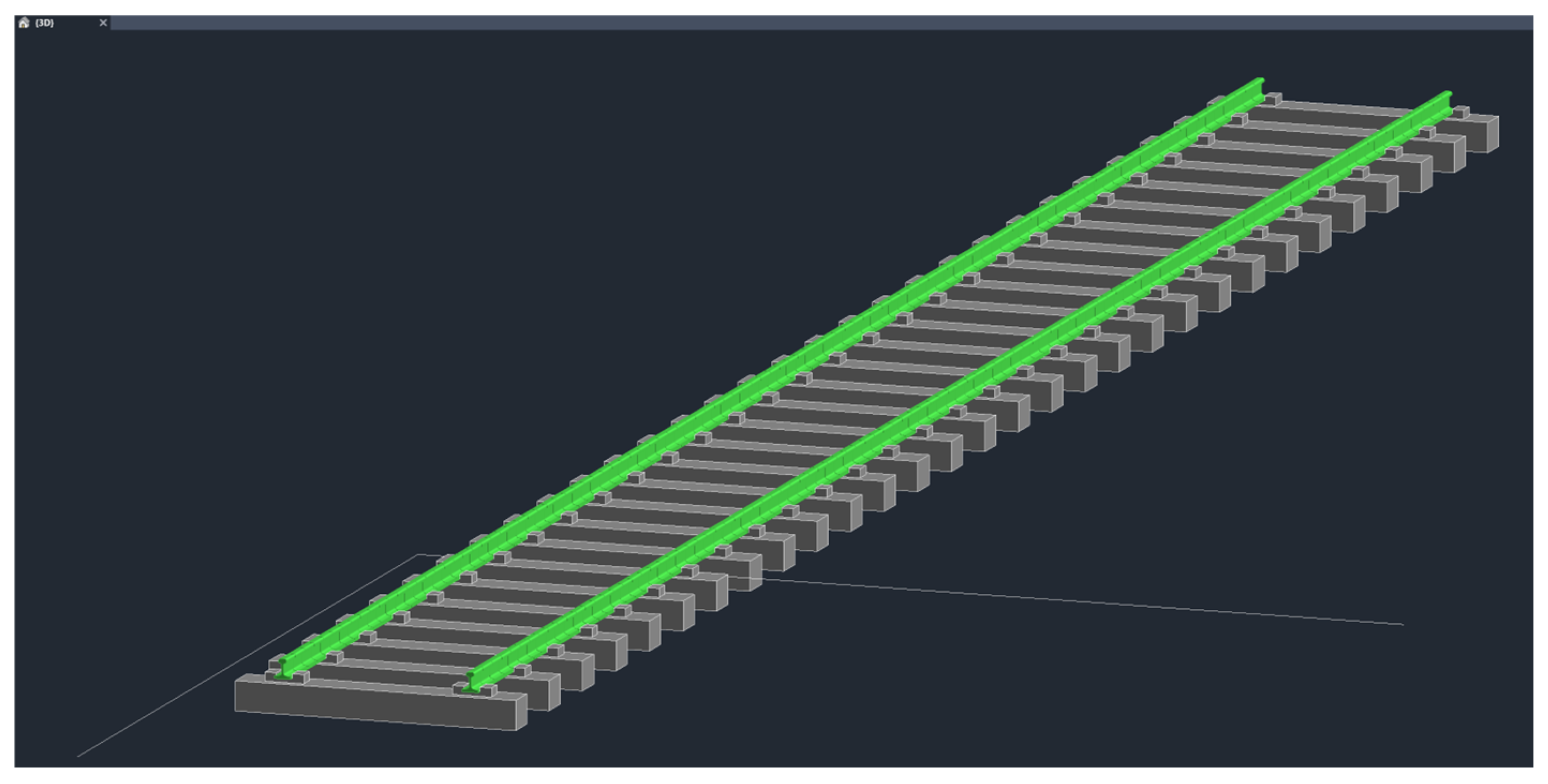
The railway segment of the case study was created as a new project in Revit. The previously generated new families of objects were first imported to the new project and the required extension of the railway track was represented. The selected number of segments corresponded to the sections where the data inspection was collected. The railway inspection report provided by the National Organization of Infrastructure contains a distinct type of data. However, for the purpose of the study, just the values related to the straight alignments were considered, corresponding to the segments that comprised the created I-BIM model (Figure 5).
The imported parametric families were complemented with a set of new parameters, in order to allow, in the next approach stage, the insertion of exterior data corresponding to the railway inspection data. Revit allows one to create, select and manage the parameters of objects. As such, a set of new parameters was associated with each segment, corresponding to the right and left rail alignments, gauge, twist, right and left longitudinal levelling and cant.

4. Railway Inspection Activity

For the maintenance of the correct configuration of a railway track, it is necessary to achieve a secure route for the railway trains. Insufficient track direction can originate the reduction of the ride feature, projection contact or even flange scramble [9]. To ensure railway operations are safe and track geometry parameters, they are usually inspected using rail track geometry cars. With the fast development of advanced technologies, several analytical estimation procedures supported on machine learning applications can be required in the railway design context, in order to predict the track degradation evolution, improve the maintenance strategy and fulfil the comfort requirement of a railway transportation system [28]. The efficient management, processing and generation of inspection data require the application of advanced computer systems. The present proposal introduces, in the inspection and data analysis tasks, new technologies referring to BIM and Dynamo [9].
The standard EN 13848:2022 is focused on the assessment and verification of track geometry, outlining criteria for measuring parameters like track gauge, alignment and cross level [26]. The standard also evaluates the track stability and resilience, pointing to advanced methods for assessing the track stiffness and resistance of the rail tracks over dynamic loads to prevent derailments.

4.1. Degradation of Railway Track Components

Safe travel on railways is an important research aspect for transportation engineers, in order to maintain railways in good condition, and is associated with a frequent inspection maintenance practice [29]. The material degradation of rail tracks’ components is an important aspect within the railway entities as it marks the railway’s comfort. When a train passes over an irregularity verified in the rail surface, the vehicle experiments with excitations that lead to the forces applied over the track components. These forces can impose an important augment of the track material’s deterioration, which leads to the increase in maintenance costs [30].
The material degradation of the rail components caused by exposure to the natural environment and the action of the train circulation reduces the efficiency, functionality and quality of the railway infrastructure. As such, periodic inspections of the railway infrastructure must be planned with regular frequency, allowing engineers to analyze the collected data and proceed with maintenance or preventive actions if required [31]. The national standard EN 13848:2022 addresses the railway track components’ material properties, providing guidance on testing methods for the materials used in rails, sleepers and fastening systems [26]. The track geometry parameters normally inspected include the track gauge, cant, longitudinal level, alignment and twist.
Ballast and sub-ballast layers placed under the train tread elements may present irregular deformations. Whether in the vertical direction or in the transverse direction, they can naturally impose serious irregularities on the structure immediately above. The ballast layer is the main component for the ballasted track. Moreover, the inspection of the ballast layer must be analyzed considering the differential deformation, under the train’s cyclic loadings after a long service time, as the ballast layer gradually loses its elasticity. The present work aims to define a strategy for modeling and analyzing the severity of irregularities, which can be applied in a broader scope in order to also incorporate the lower layers.

4.1.1. Track Gauge and Cant

The railway gauge is the distance defined between the inner faces of the heads of both rails. The track gauge is the minimum space between points P1 and P2 that is measured in a horizontal orientation with the top tangent of the railheads (Figure 6a). The ZP horizontal measure is located below the top tangent of the railheads. The value of ZP in the harmonized standard is 14 mm [32]. The track gauge is an indicator of the construction quality and the state of track maintenance. When the value of this parameter is not in conformity to the standards, it reflects the wear and degradation of the materials.
The cant of a railway track is the height variation degree between the two rails. The railway cant is measured as the elevation difference concerning the outer and inner rails (Figure 6b). This important parameter is usually controlled in order to guarantee the railway’s security and a smooth raid condition. The longitudinal cant variation supports the establishment of the tolerance limits of the track and the adequacy of maintenance plans [33]. The cant data are measured to evaluate eventual rail tracks’ deficiencies. A correct geometry measurement can support the identification of geometric irregularities over the rail surfaces, caused by material abrasion, inadequate fasteners or even an irregular rail base platform [34].
In curved railway tracks, the outer rail is elevated, providing a banked turn. This allows trains to navigate curves at higher speeds and reduces the pressure of the wheel flanges against the rails, minimizing friction and wear. The outer rail of a curved railway track is generally raised over the inner. The difference in elevation between the outer and inner rails is referred to as the cant, and in a curved track this difference is more evident.

4.1.2. Longitudinal Level and Alignment

The railway track leveling is the geometric parameter responsible for the regularity of support for moving wheelsets and ensuring the vertical stability of vehicles (Figure 7a). The settling may occur on the railway track due to the pressure applied by the passage of the train composition with heavy loads and at high speeds [35]. However, longitudinal leveling of the rail is frequently influenced by the existence of stiffer regions in the track, due to differential settlements between the free track and the firmer [36]. This type of pathology leads to irregularities in wheelset support and abrupt vertical oscillations in the rolling stock. Settling can be developed simultaneously in both tracks or alternately in one and then the other [37].
The railway track alignment is the parameter responsible for the quality of vehicle guidance and ensuring its lateral stability (Figure 7b). This leadership is accomplished by the contact of the flange of the wheelset with the inner face of the rail, known as the guiding face. The irregularities in the alignment of the controlling rail will directly affect the train’s traveling quality, causing instability, especially at high speeds. The alignment defects induce transverse oscillation in locomotive and trailing vehicles [38].

4.1.3. Twist

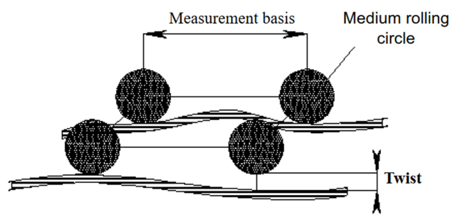
The twist pathology is characterized by sudden changes in cross levelling, resulting in irregularities in wheelset support, and potentially leading to train derailments [39]. Considering four points on the rail-bearing surface (two on each rail, forming a rectangle), the warp is defined as the vertical distance from one point to the plane formed by the other three. The twist value corresponds to the difference in two instances of cross levelling at a specific measurement base [9] (Figure 8).

4.2. Rail Inspection Metodologies

Distinct test processes can be considered in inspection work. The nondestructive testing (NDT) methods are used as preventive measures against track geometric failures and possible derailment [40]. The nondestructive evaluation (NDE) techniques can also be applied, namely, to visual detection, ultrasonic inspection or acoustic emission inspection [31]. The horizontal track geometry value can be obtained using a track geometry recording system positioned in a service vehicle.
A visual inspection or walking inspection can be applied as a first action before the use of NDT or NDE methods. The manual basic inspection is utilized to detect rail defects in track elements, materials, installed equipment and drainage systems. After this, an ultrasound instrument can be used, providing greater precision and control over the geometric defects identified on the rail track. Advanced and complex equipment can also be considered, namely, an electromagnetic inspection device, laser measurement, prospecting radars for ballast and sub-ballast inspection and ultrasonic techniques [37].
A manual inspection can be supported with the use of trolley KRAB equipment (Figure 9a) containing two measure rollers allowing one to verify the gauge, alignment, cant and twist dimension [41]. The LaserRail device (Figure 9b) allows for monitoring the rail wear with high precision, by reading the profile, and providing data concerning the material loss of the rail head [42]. The Iris 320 equipment is a railway inspection vehicle that offers digitized measurement systems, networking, information technology and flexible facilities to execute data production, resulting from the fusion of innovation and railway maintenance [43]. In the present case, the provided inspection data were collected using the EM120 track car [25].
Inspectors and work crews can use a rail inspection car to move to and from the repair work or inspection sites and carry the inspection equipment on board, including probes and transducers mounted underneath the carriages (Figure 9c). The inspection vehicle allows the testing of various parameters of track geometry without obstructing normal railroad operations. The mobile track inspection systems, easily mounted on passenger or freight trains, use a variety of sensors, measuring devices and data management software [44]. Based on the inspection data, the necessary diagnoses are then performed. The analysis of the inspection record allows engineers to prevent eventual failures and establish an adequate maintenance plan for the railway infrastructure, ensuring the safe operation of rail trains [45].
The inspection activity in railway tracks considers anomalies, in order to guarantee good structural integrity, safety and longevity. Structural Health Monitoring (SHM) has emerged as a critical tool for early damage detection and preventive maintenance. In addition, the adoption of digital twin technology, considering dynamic loads, enables continuous, data-driven monitoring and predictive analytics [46]. SHM plays a crucial role in assessing structural conditions and predicting failures to maintain structural integrity. Vibration-based condition monitoring employs non-destructive, in situ sensing and analysis of system dynamics across time, frequency or modal domains. This method detects changes indicative of damage or deterioration [47].

4.2.1. EM 120 Inspection Vehicle

In Portugal, the railway geometry inspection is supported by the use of an EM 120 vehicle [25]. It contains a global positioning system (GPS) receiver device, providing the vehicle’s geographical position, corresponding to each inspection point along the rail, and an inertial measurement unit (IMU) composed of three accelerometers. The vehicle devices are calibrated using an encoder optical measurement system, based on the distance traveled by the vehicle. The vehicle is also equipped with an optical gauge measuring system (OGMS) that measures the displacement of each rail in relation to the center of the IMU box. Measuring track geometry through the EM 120 vehicle enables a precise and reliable track measurement under load conditions, which simulates the real stresses occurring on the track under normal operating circumstances.
The collected inspection data are composed of acceleration values, transformed into displacements after double integration, along three orthogonal axes and of three rotational values that measure the angular variations around the axes. During the measurement process, a minimum speed of 18 km/h is maintained, avoiding the wrong parametric values caused by the inertial measurement unit [48].
For the present study, the national infrastructure entity provided an inspection report including the required measures. The collected data were then represented in a graphic of values’ oscillation around the rail lines, generated according to the distance measured between inspection points. The kilometric value represented the point where the measures were made, corresponding to intervals of 25 cm. These data referred to the left and right rails’ longitudinal level, twist, gauge, cant and left and right rail alignments.

4.2.2. Data Evaluation and Diagnostic

The evaluation of the obtained measurements was categorized according to the technical standard GR.IT.VIA.018, concerning the tolerances and defects of the geometric track parameters [49]. The document defines the deviation tolerances applicable over the track’s geometric parameters, considering the Iberian gauge. The guideline expresses several levels of diagnostics:
  • The alert level refers to a parameter value that did not exceed the tolerance;
  • The intervention level indicates that a value did not reach the tolerance;
  • The immediate action alert is considered when a value exceeds the tolerance.
For irregularity that exceeds the established tolerances, the type of intervention or immediate action to be implemented is defined by the function of the type of anomaly and the range of values considered in each geometric parameter, established in the standard. Therefore, in the situation of an immediate correction alert, a train speed reduction must be applied or a closure for the affected rail segment can be required.
Table 1 lists the interval of values for each geometric parameter, related to the alert level, considering the circulation speed and the tolerance level [49]. In this study, the circulation speed range between 80 km/h and 120 km/h was considered.
The data used in the inspection activity were collected during the process and actually carried out on site, as part of the regular maintenance work on railways, in the national context. The set of data selected to illustrate the application of the developed script concerned only a restricted number of anomalies, having been selected as the most frequent and striking in relation to the more or less imminent danger they may cause.

5. Dynamo Visual Programming

The generated rail I-BIM model contained not just the geometry of the rail track components and their respective physical properties, but also the required inspection parameters. The next step refers to the elaboration of a Dynamo script oriented to perform the geometric inspection evaluation.
A script is an algorithm that allows for realizing a sequence of operations to achieve a specific outcome. Dynamo is a visual programming language for Revit [50]. This language is an open-source platform and uses node-based logic programming.

5.1. Development of the Dynamo Script

Dynamo programming presents a friendly interface environment. Dynamo’s interactive interface allows users to handle the selection and connection of action nodes, the application of a wide variety of algorithms responsible for managing a distinct type of functions and the creation of facility add-ins. The programming process is intuitive and visual, but the script algorithm generation can become complex with a larger volume of operations, requiring the application of text-based programming languages like Python to introduce additional flexibility. Dynamo uses the IronPython command, enabling Python scripts to interact with the Revit plug-in.
Specific Python nodes were created and applied in the elaboration of the script. These Python nodes supported the data input action in the BIM model and the data handling in order to perform the geometric inspection, diagnostic and alert. For this process, several stages were considered:
  • As the available inspection data were organized in an Excel format, the Python node used to import the listed values into the model was the “Data.Import.Excel”;
  • Next, the selection of the railway elements was realized, using the node “Family Types” related to the rail components included in the model;
  • The imported data were then correctly associated with the respective parameter of each selected element, through the application of the “Element.SetParameterByName” and “List.GetItemAtIndex” nodes, allowing data to be connected by index;
  • An important function required for the script was the inspection of the value evaluation requiring the analyses of the parametric values, confronted by the tolerance standard values, and the attribution of a category concerning the alert level. Figure 10 shows the routine program related to the value evaluation of a parameter and the identification of the respective alert level (unchanged, alert and intervention).
  • The final step concerned the association of a color to each alert level, allowing users to visualize it over the rail I-BIM model. In Dynamo, the colors were assigned using Alpha, Red, Green and Blue (ARGB) inputs, where Alpha represented the color transparency and the others the basic colors. In the routine listed in Figure 11, each color was assigned to its respective alert level. The green color denoted no action required, yellow was the alert level, orange was the intervention level and red was an immediate action level.

5.2. Dynamo Script Application

The script was tested using the provided inspection data related to the railway case study. The generated Dynamo script was directly acceded from the Revit software (https://www.autodesk.com/products/revit-lt/overview, accessed on 16 May 2025) as a plug-in. By running the script, the result of the inspection data was then visualized over the I-BIM model, showing a coloring perception associated with each rail segment.
The available data were captured using the EM120 vehicle during a real railway inspection provided by the Department of Asset Management of the Portuguese railway infrastructure entity. The report carried out at the site was composed of 106 sections, referring to each inspection point every 25 cm along the selected rail track segment. The inspection data were first organized in an Excel spreadsheet format and then imported to the script. As an illustrative example, Table 2 presents just a short list of the values associated with four of the seven geometric parameters.
The outcomes of the script application were visualized in the main Revit software interface (Figure 12). All segments of the model presented a green color corresponding to the level “no action needed”. This result represented the evaluation of the geometric values included in the standard tolerance range for all parameters.

5.3. Evaluation of the Dynamo Script Performance

Two experiments were conducted, one using just the real provided data and the other using a changed list of values in order to illustrate the perception of colors related to distinct alert levels.
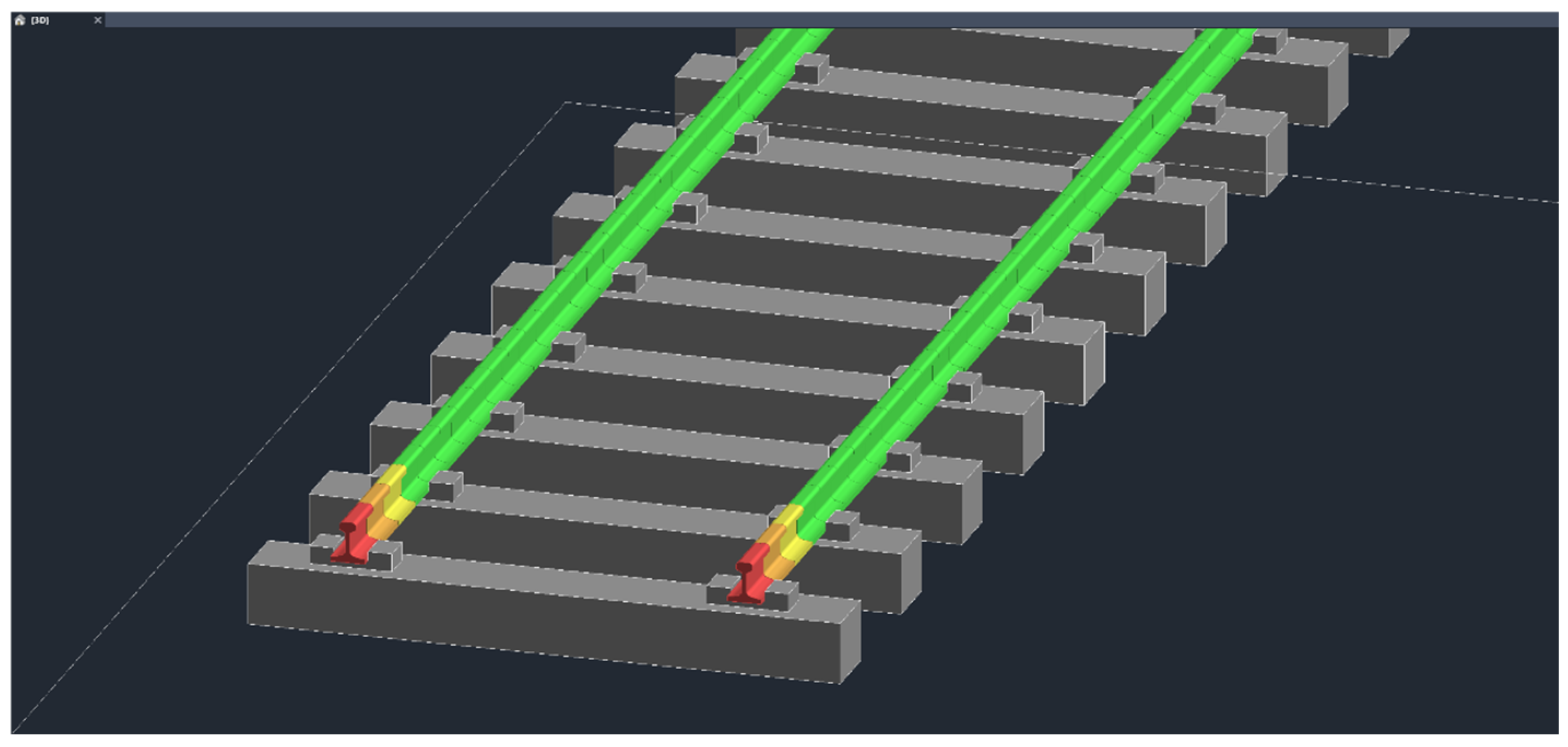
The result of the script application related to the use of unaltered data showed all rails colored green, indicating that no action was needed in all of the segments of the inspected rail track. However, for a comprehensive understanding of the script’s capabilities, alterations were made over the imported values. Some values of the first four rail sections were modified. In the first section, three of the parameter values were altered to upper values corresponding to distinct actions, namely, immediate action, intervention and alert levels. After running the script, the modified values corresponding to those actions were consequently represented in the I-BIM model by the colors red, orange and yellow, respectively. Alterations of the initial inspection data, related to the second and third sections, were also made in order to reflect in the model the different levels of alerts (Table 3).
This new table of values was tested in the script. The Dynamo script allowed the accurate representation of the alert level in each 25 cm section of the model. The red indicated an immediate action, orange an intervention action and yellow an alert action, while the other sections remained unchanged (Figure 13).
After running the script, concerning the two tables of data inspection, it was possible to evaluate the efficiency of the developed script. The illustrative results demonstrate the potential utility of the script in the railway inspection activity.

6. Results and Discussion

The visual results presented in Figure 10 and Figure 11, obtained by the application of the generated Dynamo script, demonstrate a successful achievement in empowering BIM use in railway inspection work. Both images, showing the script application results, illustrate the efficiency of the proposed approach. The study presents a useful BIM application considering the link between BIM software (2025) and Dynamo 3.3 (2025) programming, in the context of the railway track maintenance facility:
  • The present study demonstrates that the script application can identify alert levels, visualized over the model based in a coloring perception, supporting maintenance engineer work as it allows for the easy detection of the sections or rail segments with anomalies. From the analyses of the parametric values related to the irregular points, the inspection value or values that exceed the tolerance are then easily identified in the inspection report list. The access to the particular data responsible for the alert emission is also easily detected, by observing the data contained in the Excel file, related to each irregular rail section or segment. The engineer must then carry out the corresponding maintenance action, according to the geometry type and the detected level of gravity.
  • The script can be used over other I-BIM models referring to the same type of rail components considered in the present case. For that, the modeling process of other rail projects should use the BIM parametric objects generated in the study. The type of elements and shape, defined as new parametric objects related to rail track geometry, should then be applied in the generation of a new rail project. In addition, as these new rail components present an accurate geometry and are associated with the parameters required in an inspection activity, the new I-BIM model can support the script application. To proceed with the generation of other railway models, the parametric objects representing the sleepers, the fastenings and the rail track segments of 25 cm long must first be inserted as new families in the new Revit project. This I-BIM model is then composed of all rail objects associated with the necessary inspection parameters needed to perform the script application. As such, the same type of results can be easily achieved in other railway projects.
  • In addition, the script can be adjusted to other standards’ gauges, used in other countries, or to different components concerning fasteners or sleepers. The script was elaborated following the inspection data process mentioned in the national standard EN 13848:2022 [26] and tolerance guidelines of GR.IT.VIA.018 [49]. Both standard manuscripts were used to support the script application in national railway infrastructures. Other new families of parametric objects can be used to represent a national railway segment, supporting not just the generation of the respective I-BIM model but also the rail inspection activity. The script attends only to the national gauge standards. For other uses of the script, in a distinct gauge, the script must be adjusted for conformity.
The way to integrate the data in the developed I-BIM model is described in detail, including the selection of the parametric objects used in the model, and the generation of new parameters to be associated with each object, in order to receive and store the inspection data. It is also described in detail how to carry out the data analysis, using the created Dynamo script, in order to present warnings of low, moderate and high degrees of deterioration. Additionally, the example is presented with the alteration of data, in order to introduce in the model excessive values referring to three types of anomalies. This experience clearly illustrates how efficient the developed script is.
As previously mentioned, several authors were consulted. The present work presents considerable advances in the BIM field applied to the railway, and especially to the maintenance activity. Compared to Wu et al. [18], who only considered the geometric inspection relative to the gauge, the present study encompasses more inspection parameters. Additionally, unlike Ferreno et al. [19], who analyzed the mechanical properties with the application of mathematical algorithms, the developed script integrates inspection data into the model, analyzes them and visually transmits (colors) the degree of incorrectness of the anomaly. In addition, the work of Chellaswamy et al. [20], in which they presented a methodology for the detection of anomalies, did not contemplate the incorporation of specific maintenance parameters in the BIM model, as exposed in the present study.

7. Conclusions

Building Information Modeling (BIM) methodology emerged as a collaborative approach to project development, particularly within the architecture and engineering fields. Recently, its adoption in the transportation infrastructure sector has faced challenges. The present study positively contributes to the dissemination of a relevant achievement concerning the adoption of BIM methodology and Dynamo programming use, improving workflow efficiency within the railway inspection activity.
The application of the developed script in railway maintenance is both useful and promising for the future of railway inspections. Once the script is developed, the only required action from the engineer is to select the Excel document containing the collected data. The script performs the evaluation, which is currently realized by a traditional analysis of graphics and tables provided by the EM120 inspection vehicle. By integrating Revit software and Dynamo programming, the script provides a quick overview of the inspection results identified by interpreting the associated color coding, facilitating the maintenance activity. This functionality can be easily applied by maintenance engineers, enhancing efficiency in railway inspections.

7.1. BIM Benefits in Railways

For other real railway projects, the I-BIM model of the inspected segment must be first modeled, using the generated families of rail parametric objects, complemented with all the inspection parameters required to perform the geometric inspection activity. This functionality can easily be implemented by the railway engineer enterprises, supported by the direct access of the generated inspection Dynamo script, used as a Revit plug-in.
This study focused on implementing BIM methodology in railway projects, aiming to enhance inspection processes and maintenance activities throughout the infrastructure lifecycle:
  • Using the Revit BIM modeling parametric system, an I-BIM railway track model was created, focused on the essential components required for the geometric quality assessment. New parametric families were defined for sleepers, fastenings and rails, considering not just an accurate geometry but also the addition of new parameters related to the inspection work;
  • A Dynamo script was developed allowing users to transfer the collected inspection data into the railway model; to associate the data to the respective parameter of the objects, used in the modeling process; and to perform color coding according to the alert level standards;
  • The application of the new script, as an innovative approach, allows engineers to enhance optimized inspection planning, with adequate and accurate maintenance prevention, efficient streamlining workflow and a global time-saving measure.
Despite some difficulties and delays in the transport infrastructure area in comparison to other areas of application of BIM methodology, its adoption is very promising and positive. The present study encourages BIM implementation in infrastructure engineering projects and companies. BIM implementation in railway infrastructure inspection was successfully demonstrated in the text, and the main benefits were highlighted supporting the good results obtained by applying the created script. To perform the study case, an I-BIM model was first created, and then enriched with the collected inspection data. This aspect supports the main concept of BIM, which is the centralization of all information generated, added and actualized in a unique digital model of the infrastructure in analyses. The enriched BIM model allows the user to manipulate its database, leading to more efficient project coordination, management and maintenance.
In the field of railway maintenance, the use of BIM modeling is very limited. The study presents the modeling process required for a correct representation of the components of the rail track. This step was innovative because, normally, the limitation in the development of I-BIM models for projects under analysis and maintenance is due to the lack of parametric objects in the libraries of BIM systems of most frequent use. Thus, new objects had to be created. Additionally, the proposal to develop a Dynamo script, with functionality as a Revit plug-in and with the ability to analyze data and present an alert level, constitutes a significant advancement in support of the railway maintenance activity. It should also be noted that parameters and values can be changed so that the script can be easily integrated into railway design offices with a different gauge. The applicability of the script is thus not limited to the example presented but also to other concrete situations, requiring only some adjustments in the Dynamo programming.

7.2. Study Limtations and Future Directions

The present study was developed in the context of the infrastructure sector, with the objective of obtaining some new knowledge about BIM implementation in the field of railways, in the national context. This work demonstrates the capability and capacity of BIM software and the application of an innovative Dynamo script in the process of railway inspection supporting the maintenance activity of the infrastructure:
  • An adequate computing skill by the user is required. This capacity becomes increasingly important for civil engineers because learning visual programming in Dynamo and text-based syntax in Python is essential for tackling complex scenarios;
  • The modeled objects and data collected only refer to a selected set of geometric elements and irregularities. The layers of ballast and sub-ballast are not considered. Similar research work can be made following the present procedure, allowing users to conduct a larger inspection over other rail components;
  • Future development areas include expanding the analysis to include curved alignments, integrating maintenance planning with all necessary parameters to design more complete manner quality control inspection tests and developing new parametric families tailored to railway infrastructures in order to facilitate the modeling process of more comprehensive and realistic infrastructure projects.
Following this work, several areas for future development can be explored within the scope of BIM application in transportation infrastructure. This study encourages BIM implementation in infrastructure engineering projects and companies, paving the way for enhanced efficiency and innovation in the industry.

Author Contributions

Conceptualization, Z.S. and J.N.; methodology, Z.S. and J.N.; software, N.M.; validation, N.M.; formal analysis, J.N. and N.M.; investigation, N.M.; resources, N.M.; data curation, N.M.; writing—original draft preparation, Z.S.; writing—review and editing, Z.S. and J.N.; visualization, Z.S. and J.N.; supervision, Z.S. and J.N.; project administration, Z.S. and J.N.; funding acquisition, J.N. All authors have read and agreed to the published version of the manuscript.

Funding

The authors acknowledge the financial support of the Foundation for Science and Technology (FCT) through the project UIDB/04625/2025 of the research unit CERIS.

Institutional Review Board Statement

Not applicable.

Informed Consent Statement

Not applicable.

Data Availability Statement

The original contributions presented in this study are included in the article. Further inquiries can be directed to the corresponding author. The original data presented in the study are openly available in Moreira, N. Application of BIM Methodology to Railway Monitoring. Master’s Thesis, University of Lisbon, Lisbon, Portugal, 2024. Available online: https://fenix.tecnico.ulisboa.pt/cursos/mec21/dissertacao/1128253548923753 (accessed on 1 May 2025).

Conflicts of Interest

The authors declare no conflict of interest.

References

  1. Wang, T.; Chen, H.-M. Integration of building information modeling and project management in construction project life cycle. Autom. Constr. 2023, 150, 104832. [Google Scholar] [CrossRef]
  2. Omrany, H.; Ghaffarianhoseini, A.; Chang, R.; Ghaffarianhoseini, A.; Rahimian, F.P. Applications of Building information modelling in the early design stage of high-rise buildings. Autom. Constr. 2023, 152, 104934. [Google Scholar] [CrossRef]
  3. Zhang, A.; Zhou, X.; Wang, F.; Yang, J. A multi-objective optimization and display framework for time-cost-carbon emissions in building materialization phase based on nD BIM concept. J. Build. Eng. 2025, 103, 111993. [Google Scholar] [CrossRef]
  4. Khorchi, A.; Boton, C. An OpenBIM-based 4D approach to support coordination meetings in virtual reality environments. J. Build. Eng. 2024, 85, 108647. [Google Scholar] [CrossRef]
  5. Sampaio, A.Z.; Domingos, I.M.; Gomes, A.M. The 7D BIM model used in the maintenance of buildings. In Advances in Sustainability Science and Technology; Semião, J.F.L.C., Sousa, N.M.S., Cruz, R.M.S., Prates, G.N.D., Eds.; INCREaSE 2023; Springer: Cham, Switzerland, 2023. [Google Scholar] [CrossRef]
  6. Alzara, M.; Yosri, A.; Alruwaili, A.; Cuce, E.; Eldin, S.; Ehab, A. Dynamo script and a BIM-based process for measuring embodied carbon in buildings during the design phase. Int. J. Low-Carbon Technol. 2023, 18, 943–955. [Google Scholar] [CrossRef]
  7. Rocha, G.; Mateus, L. Using Dynamo for automatic reconstruction of BIM elements from point clouds. Appl. Sci. 2024, 14, 4078. [Google Scholar] [CrossRef]
  8. Sampaio, A.Z.; Domingos, I.M.; Gomes, A.M. BIM teaching and programming in dynamo applied in the maintenance of buildings. In Proceedings of the International Conference on Computer Graphics, Visualization, Computer Vision and Image Processing, Lisbon, Portugal, 20–22 July 2022. [Google Scholar]
  9. Moreira, N. Application of BIM Methodology to Railway Monitoring. Master’s Thesis, University of Lisbon, Lisbon, Portugal, 2024. Available online: https://fenix.tecnico.ulisboa.pt/cursos/mec21/dissertacao/1128253548923753 (accessed on 1 May 2025).
  10. Sampaio, A.Z.; Figueiras, J.; Gomes, A.M. The BIM methodology applied to the design of box-section viaducts (in Portuguese). In Proceedings of the National Meeting Structural Concrete, Porto, Portugal, 13–15 November 2024; Available online: https://www.fe.up.pt/be2024/sobre-o-be2024/ (accessed on 1 May 2025).
  11. Sampaio, A.Z.; Tomé, J.; Gomes, A.M. Heritage Building Information Modelling Implementation First Steps Applied in a Castle Building: Historic Evolution Identity, Data Collection and Stratigraphic Modelling. Heritage 2023, 6, 338. [Google Scholar] [CrossRef]
  12. Sampaio, A.Z. BIM multitask project manager: Responsibility, organization and interoperability. Procedia Comput. Sci. 2024, 239, 58–65. [Google Scholar] [CrossRef]
  13. Pasetto, M.; Giordano, A.; Borin, P.; Giacomello, G. Integrated railway design using Infrastructure-Building Information Modeling. The case study of the port of Venice. Transp. Res. Procedia 2020, 45, 850–857. [Google Scholar] [CrossRef]
  14. Rempelos, G.; Ognibene, G.; Le Pen, L.; Blainey, S.; Preston, J.; Powrie, W. Railway track deterioration models: A review of the state of the art. Transp. Geotech. 2024, 49, 101377. [Google Scholar] [CrossRef]
  15. Vilutienė, T.; Šarkiene, E.; Šarka, V.; Kiaulakis, A. BIM application in infrastructure projects. Balt. J. Road Bridge Eng. 2020, 15, 74–92. [Google Scholar] [CrossRef]
  16. Melo, A.L.; Kaewunruen, S.; Papaelias, M.; Bernucci, L.L.B.; Motta, R. Methods to monitor and evaluate the deterioration of track and its components in a railway in-service: A systemic review. Front. Built. Environ. 2020, 6, 118. [Google Scholar] [CrossRef]
  17. Soleimanmeigouni, I.; Ahmadi, A.; Kumar, U. Track geometry degradation and maintenance modelling: A review. Proc. Inst. Mech. Eng. Part F 2016, 232, 73–102. [Google Scholar] [CrossRef]
  18. Wu, J.; Peng, L.; Sheng, W.; Changxin, C.; Wang, J.S. Track gauge measurement based on model matching using UAV image. Autom. Constr. 2023, 155, 105070. [Google Scholar] [CrossRef]
  19. Ferreno, D.; Sainz-Aja, J.A.; Carrascal, I.A.; Cuartas, M.J.; Pombo, J.A.; Casado, S.D. Prediction of mechanical properties of rail pads under in-service conditions through machine. learning algorithms. Adv. Eng. Softw 2021, 151, 102927. [Google Scholar] [CrossRef]
  20. Chellaswamy, C.; Krishnasamy, M.; Balaji, L.; Dhanalakshmi, A.; Ramesh, R. Optimized railway track health monitoring system based on dynamic differential evolution algorithm. Measurement 2020, 152, 107332. [Google Scholar] [CrossRef]
  21. Zhang, X.; Wang, K.; Wang, Y.; Shen, Y.; Hu, H. Rail crack detection using acoustic emission technique by joint optimization noise clustering and time window feature detection. Appl. Acoust. 2020, 160, 107141–107153. [Google Scholar] [CrossRef]
  22. Chakraborty, T.; Nurain, N.; Tairin, S.; Khan, T.A.; Noor, J.; Islam, M.R.; Al Islam, A.B.M.A. A new network paradigm for low-cost and lightweight real-time communication between train and rail track to detect missing and faulty rail blocks. J. Netw. Comput. Appl. 2019, 131, 40–54. [Google Scholar] [CrossRef]
  23. Neves, J.; Sampaio, A.Z.; Vilela, M. Analysis of BIM Implementation on Railway Infrastructures through an application to rail track rehabilitation and inspection. In Advances in Transportation Geotechnics IV; Tutumluer, E., Nazarian, S., Al-Qadi, I., Qamhia, I.I., Eds.; Serie: Lecture Notes in Civil, Engineering; Springer Nature Switzerland AG: Berlin/Heidelberg, Germany, 2022; Volume 166, pp. 665–675. [Google Scholar] [CrossRef]
  24. Tomas, L. Railway infrastructure maintenance: A survey of planning problems and conducted research. Transp. Res. Procedia 2015, 10, 574–583. [Google Scholar] [CrossRef]
  25. National Organization of Transport Infrastructures of Portugal. 2025. Available online: https://www.infraestruturasdeportugal.pt/en (accessed on 1 May 2025).
  26. EN 13848:2022; Railway Applications–Track–Track Geometry quality–Part 1: Characterization of Track Geometry. ISO: Geneva, Switzerland, 2022. Available online: https://www.en-standard.eu/une-en-13848-1-2020-railway-applications-track-track-geometry-quality-part-1-characterization-of-track-geometry/?srsltid=AfmBOopKyVom0HoTiiXBomhpPROOeQ8Nja8o5nexOUioDA21wFI6GeD5 (accessed on 1 May 2025).
  27. Revit Autodesk. 2025. Available online: https://www.autodesk.com/products/revit/overview (accessed on 1 May 2025).
  28. Han, L.; Liao, Y.; Wang, H.; Zhang, H. Analysis and prediction of railway track longitudinal level using multiple machine learning methods. Meas. Sci. Technol. 2024, 35, 024001. Available online: https://iopscience.iop.org/article/10.1088/1361-6501/ad060a (accessed on 1 May 2025). [CrossRef]
  29. Elkhoury, N.; Hitihamillage, L.; Moridpour, S.; Robert, D. Degradation prediction of rail tracks: A review of the existing literature. Open Transp. J. 2018, 12, 88–104. [Google Scholar] [CrossRef]
  30. Loidolt, M.; Weilguny, R.; Marschnig, S. Impact of rail irregularities on longitudinal level deterioration based on deconvoluted data. Civ. Eng. Infrastruct. J. 2024, 9, 162. [Google Scholar] [CrossRef]
  31. Li, Q.; Zhong, Z.; Liang, Z.; Liang, Y. Rail inspection meets big data: Methods and trends. In Proceedings of the International Conference on Network-Based Information Systems, Taipei, Taiwan, 2–4 September 2015; pp. 302–308. [Google Scholar] [CrossRef]
  32. Fischer, S.; Németh, D.; Horváth, H. Investigation of the track gauge in curved sections, considering hungarian railway lines. Infras. 2023, 8, 69. [Google Scholar] [CrossRef]
  33. Tepedino, T.; Ribeiro, M.; Tressia, G. Effect of rail cant on stress distribution. World J. Adv. Eng. Technol. Sci. 2023, 9, 372–386. [Google Scholar] [CrossRef]
  34. Valehrach, J.; Riha, T.; Dušek, E. Cant excess and cant deficiency evaluation in relation to train speed. Acta Polytech. CTU Proc. 2017, 11, 80–85. Available online: https://ojs.cvut.cz/ojs/index.php/APP/article/view/4460/4335 (accessed on 1 May 2025). [CrossRef]
  35. Grossoni, I.; Powrie, W.; Zervos, A.; Bezin, Y.; Le Pen, L. Modelling railway ballasted track settlement in vehicle-track interaction analysis. Transp. Geotech. 2021, 26, 100433. [Google Scholar] [CrossRef]
  36. Varandas, J.; Silva, R.; Silva, M.; Lopes, N.; Holscher, P. The impact of rail corrugation on the degradation of the ballast. In Proceedings of the International Conference on Railway Technology: Research, Development and Maintenance, Las Palmas de Gran Canaria, Spain, 18–20 April 2012. [Google Scholar] [CrossRef]
  37. Weston, P.; Roberts, C.; Yeo, G.; Stewart, E. Perspectives on railway track geometry condition monitoring from in-service railway vehicles’. Veh. Syst. Dyn. 2015, 53, 1063–1091. [Google Scholar] [CrossRef]
  38. Alqatawna, A.; Sánchez-Cambronero, S.; Gallego, I.; López-Morales, J.M. A graphical method for designing the horizontal alignment and the cant in high-speed railway lines aimed at mixed-speed traffic. Sustainability 2022, 14, 8377. [Google Scholar] [CrossRef]
  39. Mohammadzadeh, S.; Heydari, H.; Karimi, M.; Mosleh, A. Correlation analysis of railway track alignment and ballast stiffness: Comparing frequency-based and machine learning algorithms. Algorithms 2024, 17, 372. [Google Scholar] [CrossRef]
  40. Gong, W.; Akbar, M.F.; Jawad, G.N.; Mohamed, M.F.P.; Wahab, M.N.A. Nondestructive testing technologies for rail inspection: A review. Coatings 2022, 12, 1790. [Google Scholar] [CrossRef]
  41. Trolley KRAB. Available online: https://kzv.cz/wp-content/uploads/2021/10/NCI-EN.pdf (accessed on 1 May 2025).
  42. Laser Rail Inspection System. Available online: https://www.pavemetrics.com/applications/rail-inspection/laser-rail-inspection-system/ (accessed on 1 May 2025).
  43. Iris 320 Railway Inspection Vehicle. Available online: https://youngtransportpro.com/wp-content/uploads/2021/08/20_iris320.pdf (accessed on 1 May 2025).
  44. Wang, H.; Berkers, J.; Hurk, N.; Layegh, N.F. Study of loaded versus unloaded measurements in railway track inspection. Measurement 2021, 169, 108556. [Google Scholar] [CrossRef]
  45. Ye, Y.; Li, H.; Wang, Q.; Li, F.; Yi, C.; Peng, X.; Huang, C.; Zeng, J. Fault diagnosis of railway wheelsets: A review. Measurement 2025, 242 Pt E, 116169. [Google Scholar] [CrossRef]
  46. Rahmat Rabi, R.; Monti, G. Genetic Algorithm-Based Model Updating in a Real-Time Digital Twin for Steel Bridge Monitoring. Appl. Sci. 2025, 15, 4074. [Google Scholar] [CrossRef]
  47. Rabi, R.R.; Vailati, M.; Monti, G. Effectiveness of Vibration-Based Techniques for Damage Localization and Lifetime Prediction in Structural Health Monitoring of Bridges: A Comprehensive Review. Buildings 2024, 14, 1183. [Google Scholar] [CrossRef]
  48. Mei, G.; Chen, G. Slip of wheels on rails: The root cause for rail undulant wear. Wear 2023, 523, 204727. [Google Scholar] [CrossRef]
  49. GR.IT.VIA.018 Tolerance Geometric Track Parameters (in Portuguese). Available online: https://www.infraestruturasdeportugal.pt/sites/default/files/inline-files/NormativosInternos.pdf (accessed on 1 May 2025).
  50. Dynamo Version for Revit. Available online: https://dynamobim.org/ (accessed on 1 May 2025).
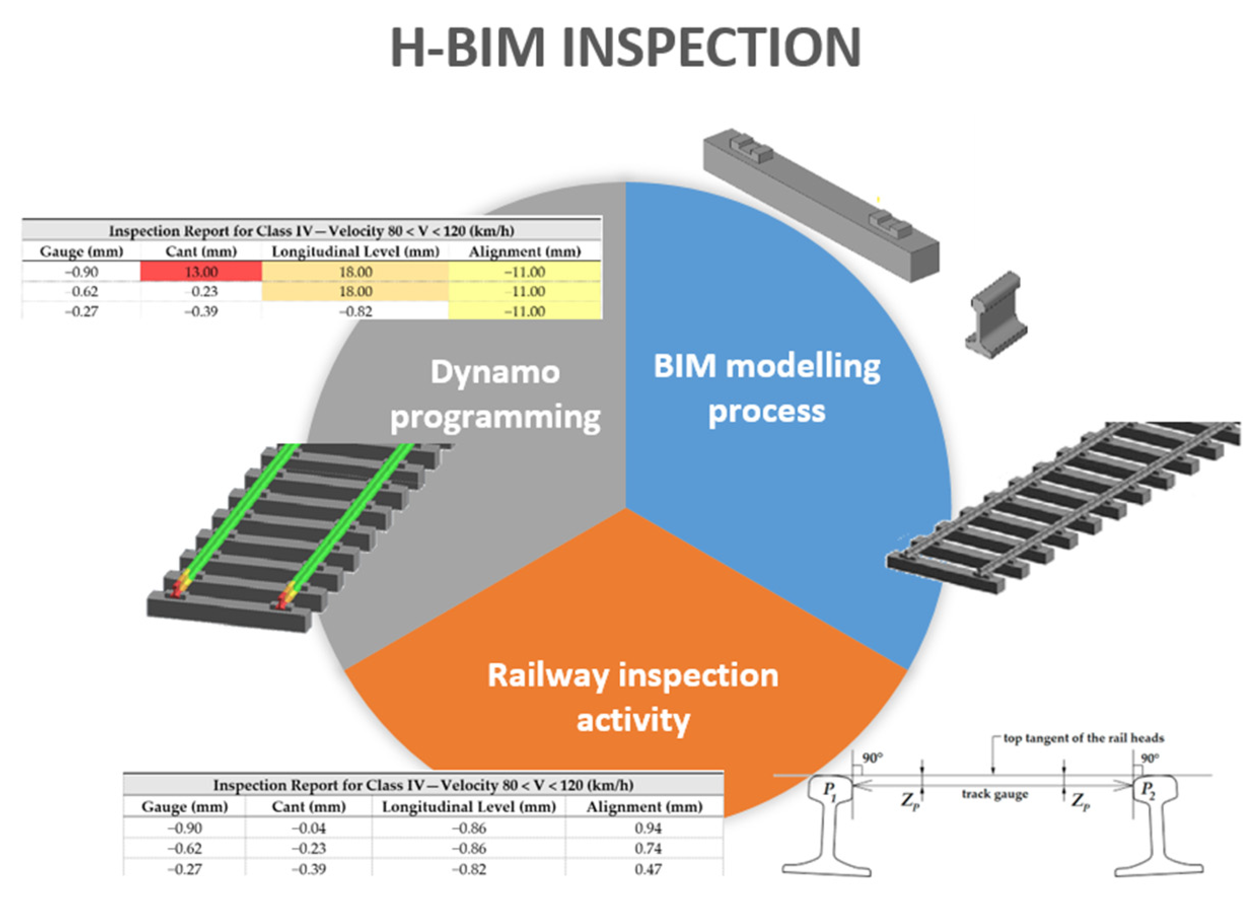
Figure 1. Scheme of the methodology applied in the research.
Applsci 15 05733 g001
Figure 2. Railway superstructure components [25].
Applsci 15 05733 g002
Figure 3. Illustration of a sleeper with fastenings (a) and a set of sleepers (b).
Applsci 15 05733 g003
Figure 4. Duo of BIM rail segments (a), Iberian gauge dimension (b) and the twin arrays of rails (c).
Applsci 15 05733 g004
Figure 5. I-BIM model of the railway track segment.
Applsci 15 05733 g005
Figure 6. Measurement of the railway gauge (a) [32] and cant (b) [33] parameters.
Applsci 15 05733 g006
Figure 7. Measurement of the longitudinal level (a) and alignment (b) parameters [9].
Applsci 15 05733 g007
Figure 8. Measurement of the twist railway parameter [9].
Applsci 15 05733 g008
Figure 9. A trolley KRAB equipment (a), laser rail inspection system (b) and the inspection car (c).
Applsci 15 05733 g009
Figure 10. Function related to the alert level for the track gauge parameter.
Applsci 15 05733 g010
Figure 11. ARGB code color assigned to each alert level.
Applsci 15 05733 g011
Figure 12. Result of the Dynamo script application identifying “no action needed”.
Applsci 15 05733 g012
Figure 13. Result of Dynamo script application considering data adjustment.
Applsci 15 05733 g013
Table 1. Tolerance of rail geometric parameters for alert level and velocity [80–120] km/h (adapted from [47]).
Class IV—Velocity 80 < V < 120 (km/h)
Gauge (mm)Cant (mm)Longitudinal Level (mm)Alignment (mm)
−7/+25−12/+12−13/+13−10/+10
Table 2. Sample of inspection data imported to the model using the script (adapted from [25]).
Inspection Report for Class IV—Velocity 80 < V < 120 (km/h)
Gauge (mm)Cant (mm)Longitudinal Level (mm)Alignment (mm)
−0.90−0.04−0.860.94
−0.62−0.23−0.860.74
−0.27−0.39−0.820.47
−0.23−0.39−0.700.12
0.00−0.43−0.62−0.31
0.08−0.43−0.51−0.86
−0.27−0.39−0.39−1.29
−0.66−0.20−0.23−0.52
−1.02−0.04−0.08−0.56
−1.21−0.270.04−0.52
Table 3. Sample with some inspection values modified.
Inspection Report for Class IV—Velocity 80 < V < 120 (km/h)
Gauge (mm)Cant (mm)Longitudinal Level (mm)Alignment (mm)
−0.9013.0018.00−11.00
−0.62−0.2318.00−11.00
−0.27−0.39−0.82−11.00
−0.23−0.39−0.700.12
0.00−0.43−0.62−0.31
0.08−0.43−0.51−0.86
−0.27−0.39−0.39−1.29
−0.66−0.20−0.23−0.52
−1.02−0.04−0.08−0.56
−1.21−0.270.04−0.52
Disclaimer/Publisher’s Note: The statements, opinions and data contained in all publications are solely those of the individual author(s) and contributor(s) and not of MDPI and/or the editor(s). MDPI and/or the editor(s) disclaim responsibility for any injury to people or property resulting from any ideas, methods, instructions or products referred to in the content.