Abstract
Holographic optical elements (HOEs) are promising for solar energy collection due to their advantages of lightweight and high efficiency, but the narrow reconstruction of their angular and spectral widths limits their application. This paper proposes a novel holographic lens array solar collector (HLASC), which can collect light from a large angle range with an expanded spectrum. The large acceptance angle is achieved by a holographic lens array with a large relative aperture. To expand the collection spectral width within a large incident angle, the collection spectrum is spatially allocated within a single lens range. The methods of single-wavelength recording and multi-wavelength reconstruction contribute to the flexible design and simple fabrication of the HLASC. The optical experiment demonstrates that the HLASC can collect the entire visible spectrum in a range greater than 54°. We believe that an expanded reconstruction angle and wavelength will promote the widespread application of HOEs in solar energy collection.
1. Introduction
A solar collector is a device that modulates sunlight to achieve solar energy concentration by various optical elements. The capture and accumulation of solar energy avoids the high cost and low portability of large-area solar cells, offering competitive applications in industries requiring energy harvesting, such as construction [1,2,3], agriculture [4], and transportation [5]. Compared with traditional geometric optical elements [6,7] and diffractive optical elements [8,9,10], holographic solar collectors [11,12,13,14] have the advantages of lightweight, small size, high flexibility, and high multiplexing capability, demonstrating irreplaceable application as compact and efficient solar collectors.
Nevertheless, the limited reconstruction angle and wavelength of holographic optical elements are important challenges to overcome in order to achieve a tracking-free solar energy collector that can work all day. On the one hand, due to the constant movement of the sun throughout the day, a small collection angle will result in a shorter effective working time of the system. Adding solar tracking equipment [15] can extend the effective working time, but this additional device will also increase the burn, cost, and complexity of the system. On the other hand, a narrow collection spectrum means that only a small portion of the wide-spectrum of sunlight is efficiently collected. Moreover, in some solar collectors that require perspective observation [16], a narrow collection spectrum will also cause strong color deviations between observed and real environments.
There have been some early efforts to address the angular and spectral limitations of holographic solar collectors (HSC). In order to improve the acceptance angle of HSC, a low spatial frequency recording method [17,18,19], angle multiplexing method [20,21,22,23], and multi-layer method [11,24] have been proposed, which led to several discoveries. Firstly, reducing the spatial frequency of the recorded microstructure can expand the reconstruction angle, but the expanded angle is unable to exceed 5°, which is far from the requirement of tens of degrees. Secondly, multiplexing several holographic lenses with different angles can expand the collection angle to approximately 60°, but this expansion often comes at the cost of decreased diffraction efficiency. Finally, regarding the angle multiplexing and multi-layer methods, the efficiency within the entire large angle range is not always high, but there are several central angles with obvious advantages in efficiency. In order to broaden the collection spectral width of HSC, researchers have proposed a spectral separation method [25,26,27,28] and wavelength multiplexing method [29]. However, the former method can only expand the collection spectrum into a few discrete narrow bands, while the latter method can only widen the spectrum at a fixed incident angle. Ultimately, various methods have been proposed that improve the collection angle and spectrum of HSC. However, expanding both the collection angle and spectrum simultaneously is still a problem that needs to be solved.
This paper proposes a holographic lens array solar collector (HLASC) composed of an off-axis holographic lens array, which can expand the collection angle and spectrum at the same time. We first analyze the relationship between the parameters of the holographic lens array and the collection angle of the HLASC. In addition, in order to expand the collection spectral width, a spectrum spatial allocation method based on single wavelength recording for multi-wavelength reconstruction is proposed. Subsequently, a universal design method for flexible HLASCs with different parameters is established. Finally, the feasibility and rationality of this method for an HLASC with a large angle and wide spectrum are verified through optical experiments. This work overcomes the limitations of the HOE’s selectivity of the collection angle and spectrum, thus contributing to a lightweight, large-angle, and high-efficiency solar collector. It is also expected to further promote the applications of HOE in more broadband light modulation fields.
This paper is arranged as follows: Section 2 introduces the working principle of a large angle HLASC and the method of spectrum expansion within a large angle range; Section 3 shows the optical experiments and analyzes the results of the collection angle and spectrum. In the discussion, we summarize the contributions of this paper and consider future research directions.
2. Principle
2.1. Working Principle of HLASC
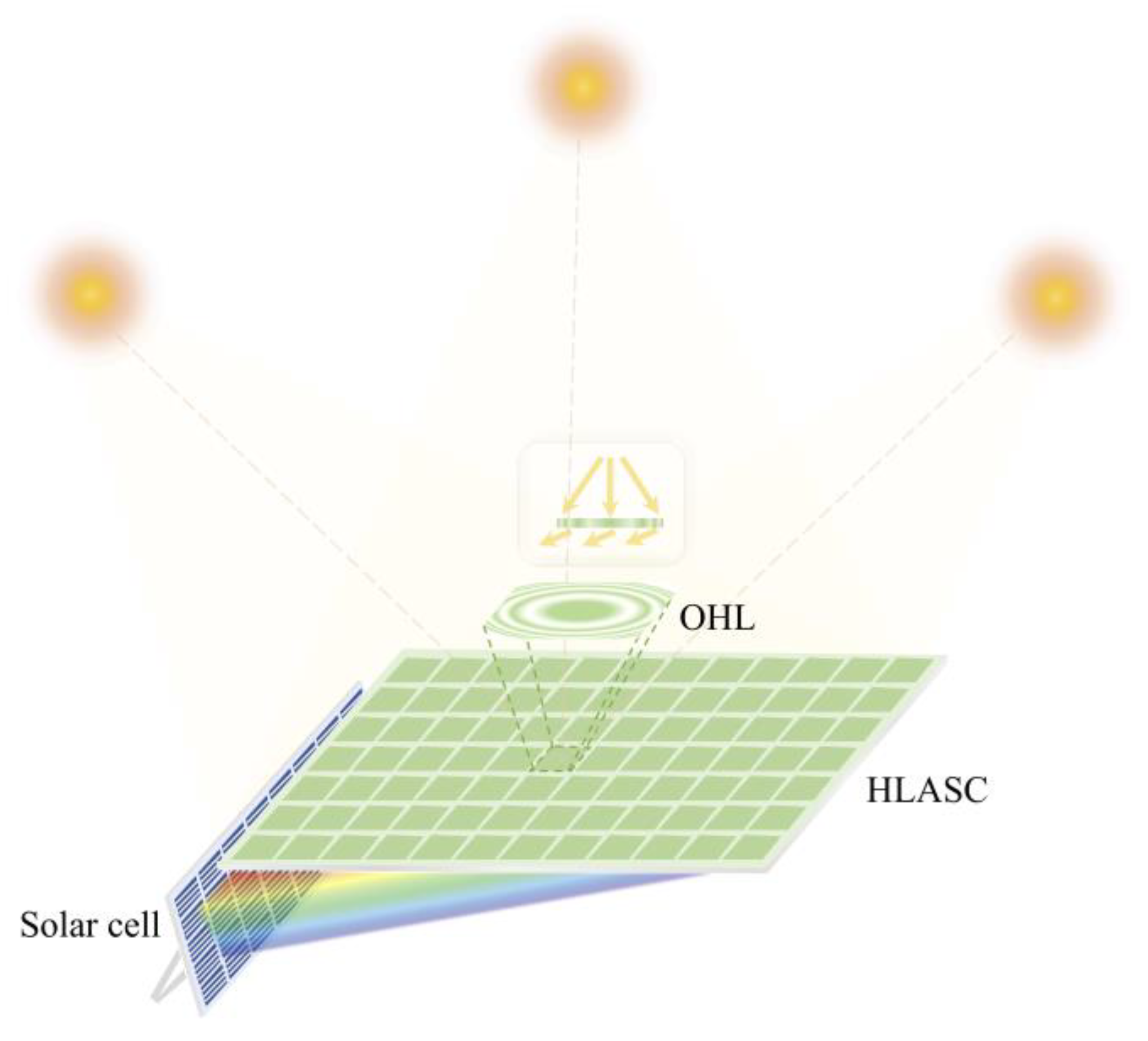
The working principle of the proposed HLASC is shown in Figure 1. The HLASC contains many periodically arranged off-axis holographic lenses (OHL), which diffract incident light from a large angle range to the solar cell located below the side. In the recording process of the HLASC, a lens array with a large relative aperture (the ratio of effective aperture to focal length) provides a recording light with a large convergence angle, allowing each OHL to achieve large angle reconstruction and thus have a large collection angle. It should be pointed out that the recording light is divergent spherical light, and the reconstructing sunlight is approximately parallel light. Due to the mismatch of Bragg conditions, the diffraction efficiency of the recording wavelength at a certain angle will not be high. However, the decrease in diffraction efficiency at the recording wavelength leads to an improvement in the average diffraction efficiency of a wider spectrum (see Section 2.2 for details), so sunlight can also be effectively collected within the whole convergence angle. Therefore, we can define the convergence angle of the recording light as the collection angle. Specifically, the relationship between the collection angle and the lens array parameters is as follows:
where D is the effective aperture of each small OHL, and f is the focal length of OHL.
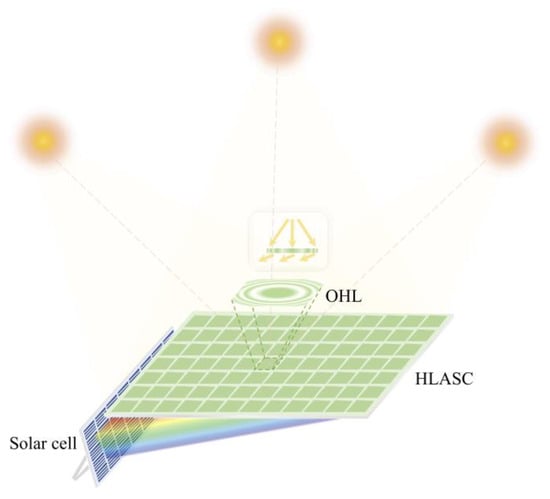
Figure 1.
Schematic diagram of the working principle of the HLASC.
The two-dimensional array structure enables each small area of the HLASC to have a large collection angle, which is a significant advantage compared to a single holographic lens structure. Different from traditional holographic solar collectors that typically utilize the focusing properties of holographic lenses to reduce the area of the solar cell, it is the off-axis layout in our system that greatly reduces the area of solar cell. In other words, the HLASC achieves the concentration of solar energy by deflecting sunlight.
2.2. Spectral Width Expansion Within a Large Angle
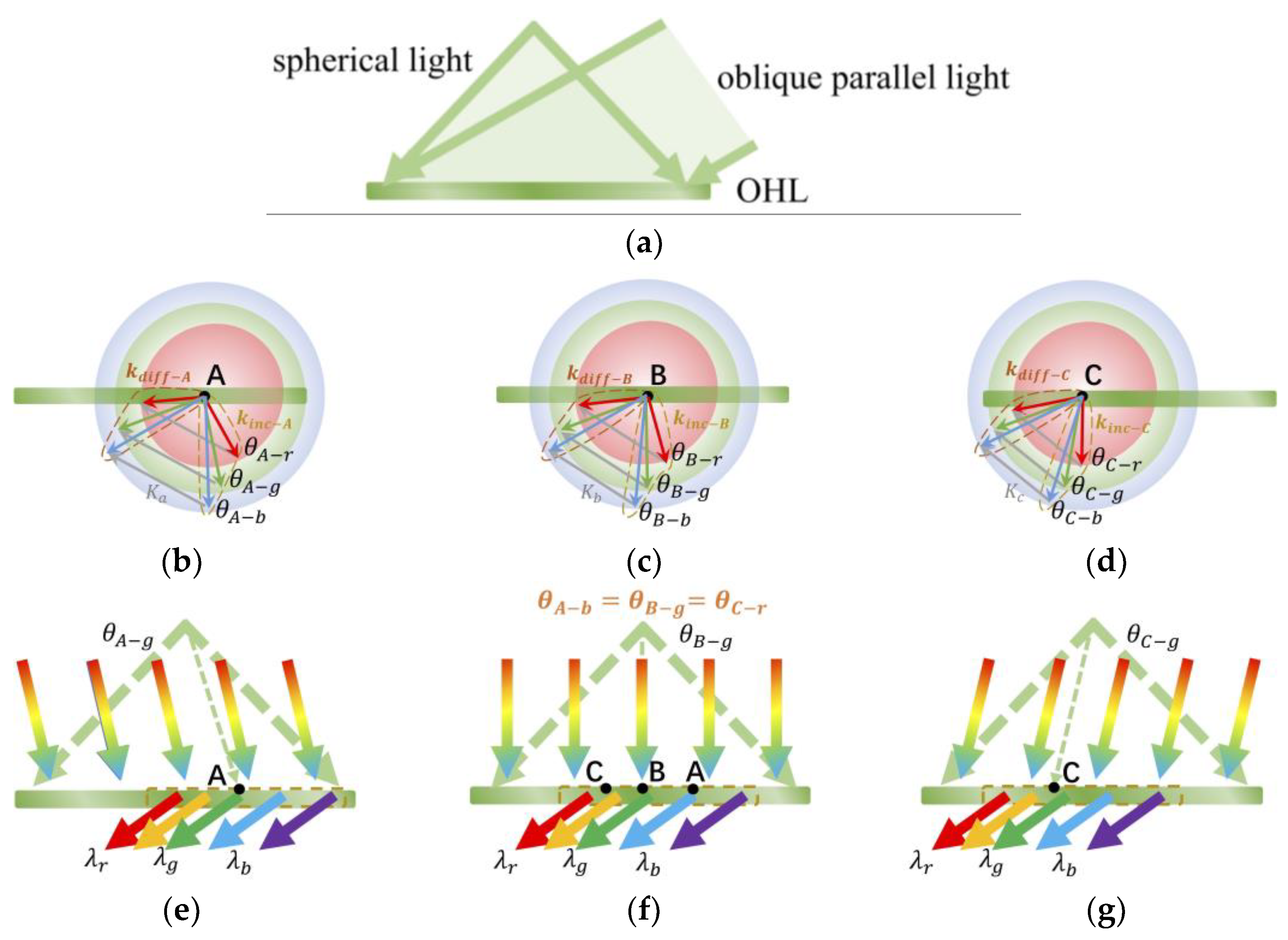
Due to the fact that each OHL in the HLASC is identical, the following analysis within the scope of an OHL unit is applicable to the entire HLASC. As shown in Figure 2a, OHL is recorded by two beams. One is a spherical light formed by parallel light entering the lens array, which corresponds to the incident light. Another is an oblique parallel light to provide an off-axis angle, which corresponds to the diffracted light. Generally, OHL is considered as a whole for reconstruction analysis. Due to the different reconstruction results of different regions, OHL is considered as many tightly arranged points in the following analysis.
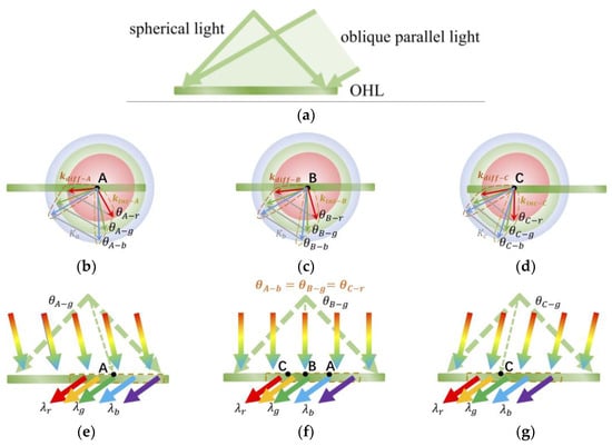
Figure 2.
Recording and reconstruction analysis of OHL. (a) Schematic diagram of the recording. (b–d) are the multi-wavelength reconstruction analyses of point “A”, “B”, and “C” of OHL, based on k-vector analysis, respectively. The red, green, and blue arrows represent the wave vectors of the incident light and diffracted light of the corresponding colors, respectively. (e–g) are the spectrum spatial allocation results for different incident angle , , and .
Firstly, we only consider a certain point “A” on the OHL, as shown in Figure 2b. The recording light is green light, as shown by the two wave vectors indicated by the green arrows. In the reconstruction process, when green light is incident at , it can be efficiently diffracted, while light with other wavelengths that are incident at this angle experience a sharp decrease in diffraction efficiency due to the mismatch of Bragg conditions. However, this wavelength shift can be compensated by angular deviation. As shown by the the red and blue arrows in Figure 2b, when red and blue light are incident at angles and , which deviate from , respectively, the grating vector, reconstructed vector, and diffracted vector can still form a closed triangle on the vector circle. Therefore, red and blue light can also be efficiently diffracted by point “A”. Similarly, every point on OHL conforms to the above analysis, as shown in Figure 2c,d. In summary, every point on OHL can efficiently diffract a wide spectrum of light, but different diffraction wavelengths correspond to different incident angles.
Based on the wide spectrum reconstruction characteristics mentioned above, due to the different recording angles of the spherical light at each point of OHL, when a wide-spectrum light is incident on OHL at a certain angle, different points on OHL will diffract different wavelengths, as shown in Figure 2e–g. Typically, as shown in Figure 2f, when a wide-spectrum light is vertically incident on OHL, points “A”, “B”, and “C” will efficiently diffract blue, green, and red light, respectively, which is consistent with the analysis in Figure 2b–d. Therefore, the spatial allocation for the collection spectrum is achieved. Similarly, OHL can also diffract wide-spectrum incident light at other incident angles, but the results of spectrum spatial allocations are different, as shown by the brown dashed boxes in Figure 2e–g. Based on the above analysis, OHL achieves the spectral width expansion of collected sunlight over a large angle range by using a single wavelength recording of a spherical wave and a plane wave. Moreover, we can flexibly design the wavelength and angle of recording light according to different demands, which will be analyzed in detail below.
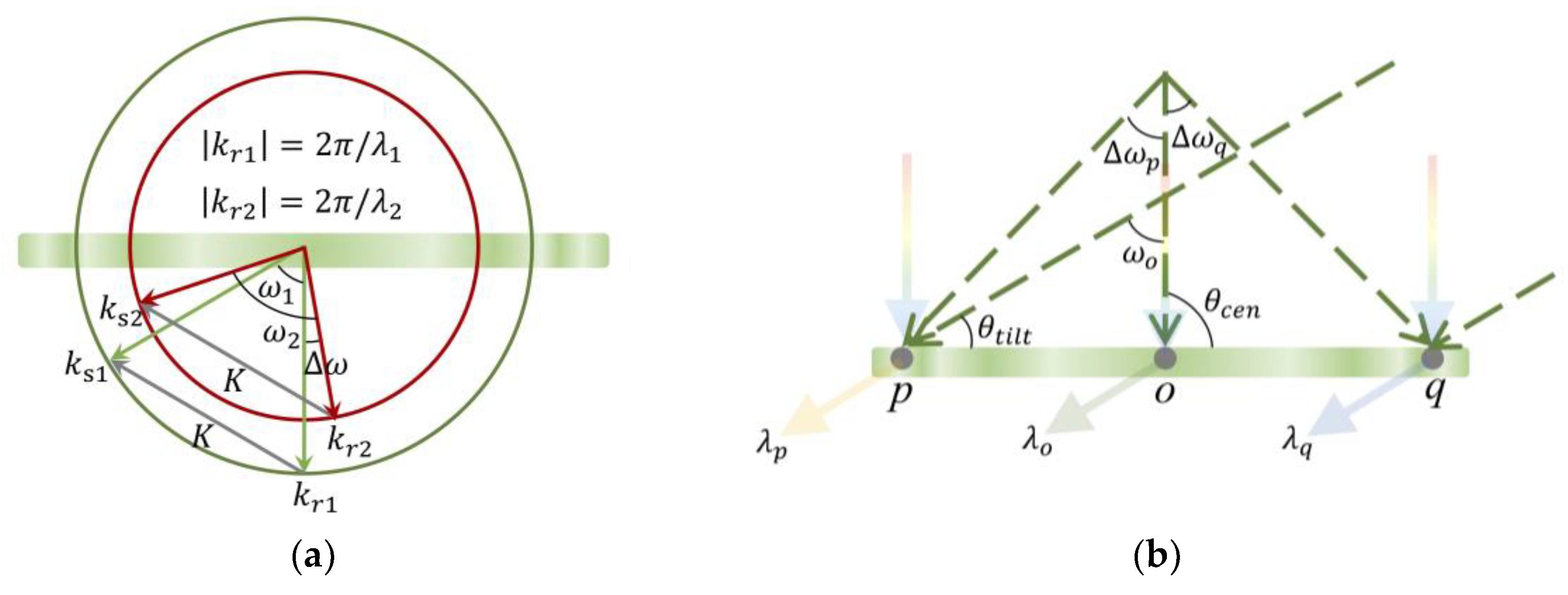
Obviously, the collection spectrum of the HLASC is the same as the diffraction spectrum of OHL. The diffraction spectrum of OHL is related to the recording conditions, and the specific analysis is as follows. It is worth mentioning that the below angles are all in the holographic material, not in the air. As shown in Figure 3a, when recording OHL with wavelength and reconstructing it with wavelength , the deviation angle between the reconstruction and recording vectors can be expressed as follows:
where and are the angles between the two recording wave vectors and two reconstruction wave vectors, respectively. When , ; when , . According to geometric relationships, there exists the following relationship between two angles:
where kr1 and kr2 are the wave vectors of the incident light during recording and reconstruction. Additionally, the relationship between kri (i = 1, 2) and wavelength is as follows:
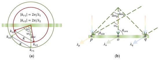
Figure 3.
The model for analyzing the diffraction spectrum of OHL. (a) K-vector analysis model for the reconstruction with a variable wavelength. The green and red arrows represent the wave vectors during recording and reconstruction, respectively. (b) Multi-wavelength reconstruction model of OHL with spectrum spatial allocation.
Combining Equations (2)–(4), there exists the following relationship:
In this case, the reconstruction wavelength can be calculated using Equation (6) based on the recording wavelength , the recording angle , and the reconstruction deviation angle . Due to the non-uniform grating structure of OHL, the above process is used to analyze the reconstruction situation of a certain point. The diffraction wavelength of OHL varies monotonically within the diameter, so the diffraction wavelength on the two edge recording points can be analyzed to determine the overall diffraction spectrum. As shown in Figure 3b, the recording light is indicated by the green dashed arrow. For vertically incident wide-spectrum light, the diffraction wavelength at point “o” is the same as the recording wavelength , and according to Equation (6), the diffraction wavelengths and at the two edge points “p” and “q” can be expressed as follows:
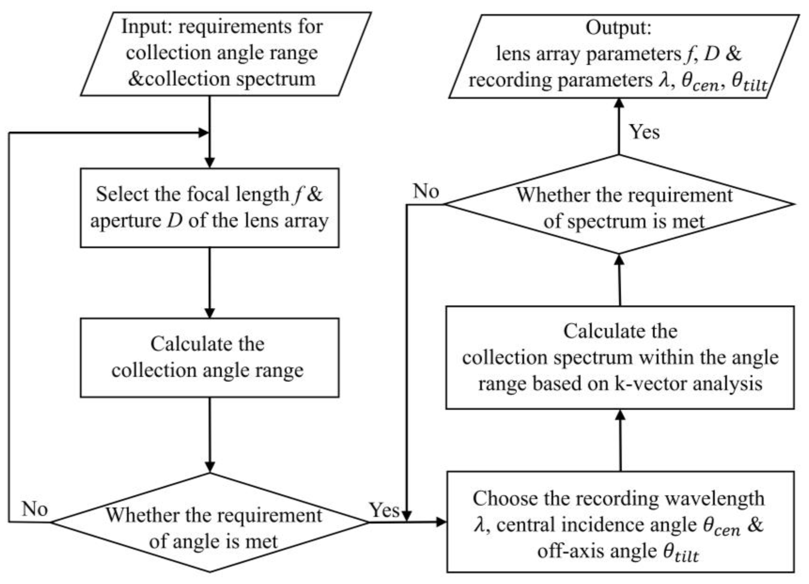
where is the angle between the two recording wave vectors at the center point “o”, and where and are the deviation angles between the incident light at points “p” and “q” and the incident light at the center point “o” during recording, respectively. It should be noted that and do not represent the same angle difference. The former represents the difference between the reconstructed angle and the recorded angle at a certain point of OHL during the variable wavelength reconstruction process, while the latter represents the difference in the incident angle of the spherical wave at different points of OHL during the recording process. Therefore, the diffraction spectrum of the entire OHL is ~. In different application scenarios, the collection angle and spectrum required for the HLASC may be different. At this point, the aperture of lens, focal length, recording wavelength, and angles can be flexibly designed according to the requirements. The specific design flowchart is shown in Figure 4.
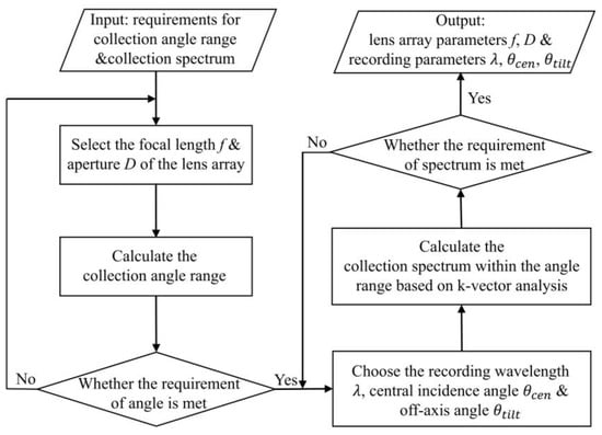
Figure 4.
Flowchart for flexible design of HLASC with different parameters.
3. Experimental Results
3.1. Acceptance Angle of HLASC
Based on the above principle, we fabricate an HLASC using a lens array with a single lens aperture of 1 cm and a focal length of 1 cm. The holographic recording material used for fabricating the HLASC is a photopolymer, and its post-processing only requires a simple step of UV curing. Additionally, the holographic material is placed parallel to the lens array with a distance of 2 cm between them, and the off-axis reference light is tilted at an angle of 70°. The wavelength of the laser used for fabrication is 532 nm, the total laser power is 300 mw, and the total exposure time is 10 s. The size of the HLASC is 5 cm × 5 cm, and the HLASC is composed of twenty-five OHLs. To compare the collection angles and spectra, we also remove the lens array and fabricate a holographic grating using two parallel lights as a reference. To avoid the influence of ambient light on the diffraction spectrum to be measured, we used an approximately collimated white light flashlight with an LED light source to simulate broad-spectrum sunlight for the following measurements.
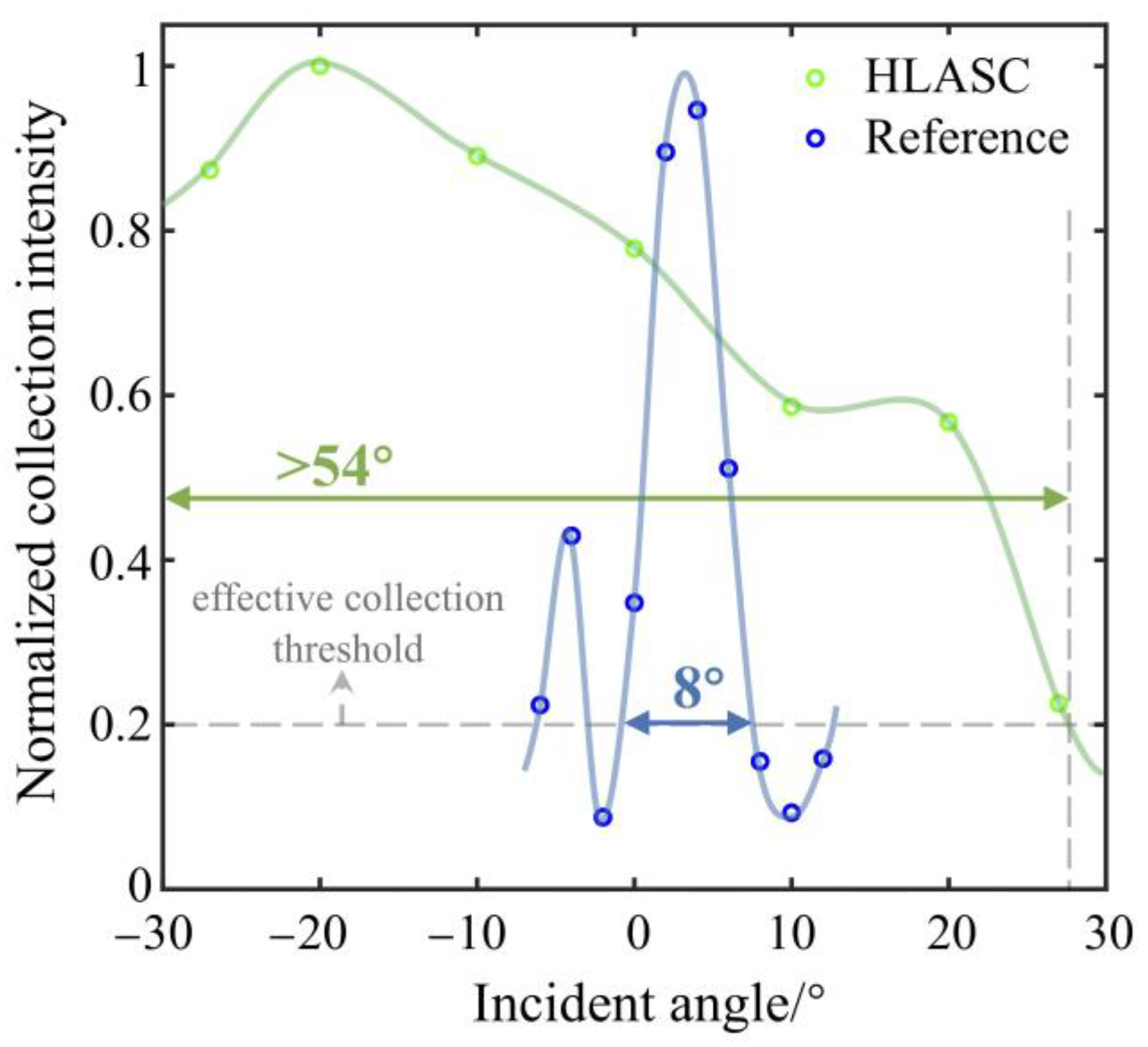
Firstly, the acceptance angle of the HLASC is tested. We use the white light flashlight to illuminate the fabricated HLASC and the reference holographic grating. A white cardboard is placed on the side to receive the collected light, and a spectrometer is placed in a fixed position facing the white cardboard to measure the spectrum of the collected light. We test the collection spectra of the HLASC and the reference holographic grating at different incident angles by changing the direction of the flashlight. Then, we process the measurement results by integrating the spectral collection curve to obtain the overall collection intensity of the HLASC and reference holographic grating, and normalize the values at different angles according to their respective maximum values. The results are shown in Figure 5. The green part represents the results of the proposed HLASC, the blue part represents the results of reference holographic grating, the dots represent the measured values, and the solid line represents the fitted curve. We define 20% of the maximum collection intensity as the effective collection threshold. The results indicate that the effective collection angle of the HLASC is greater than 54°, which is significantly higher than the 8° collection angle of the reference grating. According to Equation (1), under these fabrication parameters, the theoretical collection angle of the HLASC is 53.13°. The actual measured value is higher than the theoretical value, which may be due to the fact that the collection wavelength is no longer limited to the recording wavelength, and the collection angle will also be further expanded slightly. It should be pointed out that the spectrum of the flashlight is only in the visible light band, and we only use it to verify the effectiveness of the angular and spectral expansion method. There is also the possibility of the selective collection of ultraviolet and infrared bands of sunlight, as long as the recording conditions are designed reasonably according to the method shown in Figure 4. The parameters of the lens array used for fabricating the HLASC are also not limited to the above parameters.
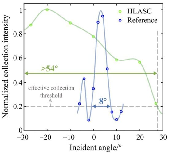
Figure 5.
Normalized collection intensity at different incident angles.
3.2. Spectral Width Expansion Effect
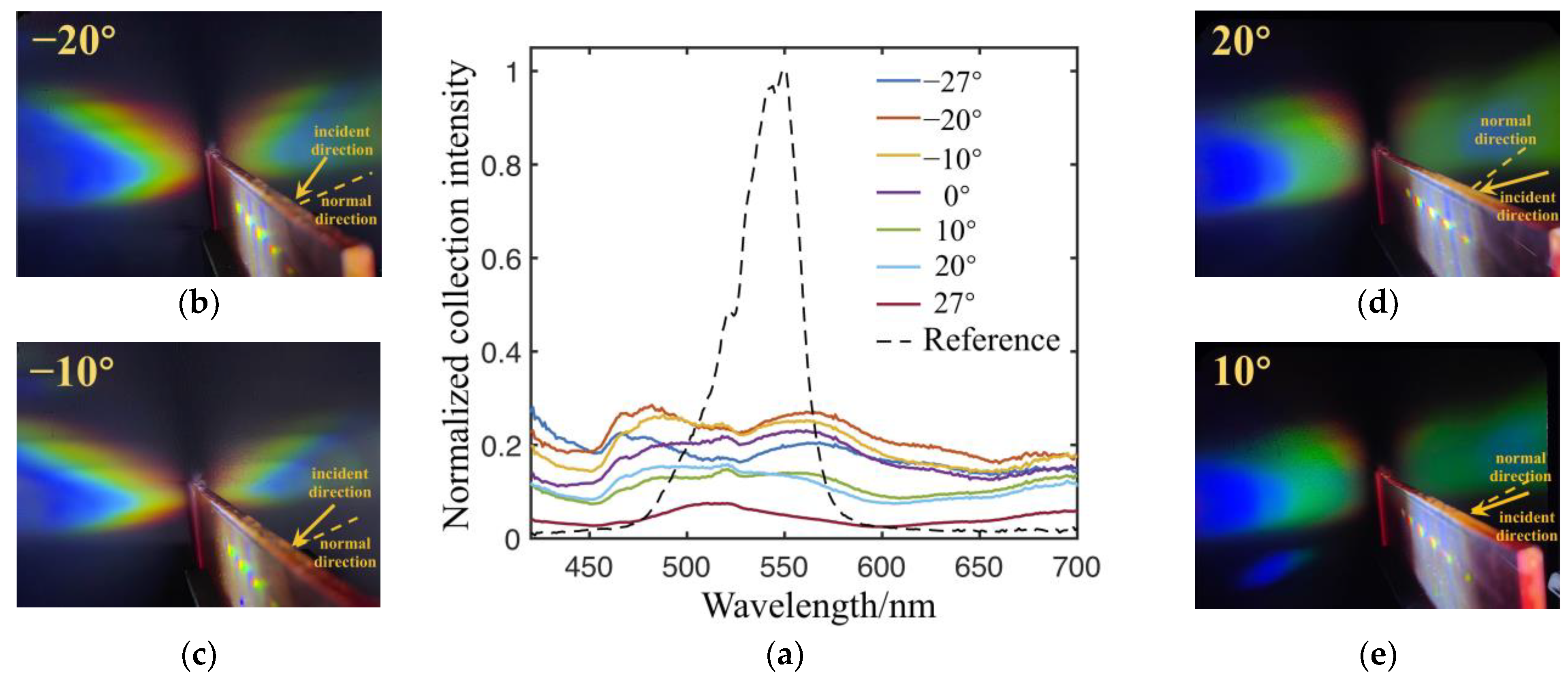
To verify the effectiveness of collection spectrum expansion, we measure the normalized spectral collection efficiency of the HLASC and the reference holographic grating. The spectral collection efficiency is the ratio of the spectral collection intensity curve described in 3.1 to the incident spectral intensity, where the normalization factor is the maximum collection efficiency of the reference holographic grating. It should be pointed out that the collection efficiency refers to the optical diffraction efficiency, excluding the conversion of solar cells. The results are shown in Figure 6a, where the black dashed line represents the measurement results of the reference holographic grating at the Bragg angle and the colored solid line represents the measurement results of the HLASC at different angles. It can be seen that the maximum collection efficiency of the HLASC is lower than that of the reference holographic grating, but the collection spectrum width of the reference holographic grating is only about 70 nm. However, the collection spectrum of our proposed HLASC extends to the entire visible light band within the incident range of −27° to 27°, which is consistent with the color collection light patterns at different angles, as shown in Figure 6b–e. In addition, after calculation, the average collection efficiency of the HLASC in the 54° incident angle range is 2.1 times higher than of the reference in the central incident angle. As is well known, the solar spectrum is very wide, and solar energy is not limited to a certain band. For the reference grating, even if there is a high diffraction efficiency for recording wavelength, the overall collected energy may still be low. After optimization, the HLASC expands the spectrum of collected sunlight, facilitating the collection of more solar energy. In other words, the spectral expansion effect can significantly improve the collection energy of sunlight by increasing the average diffraction efficiency of a wider spectrum.
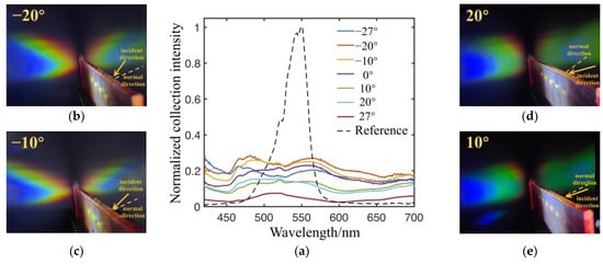
Figure 6.
Normalized spectral collection efficiency and diffraction patterns at different incident angles. (a) Normalized spectral collection efficiency. (b–e) are diffraction patterns at −20°, −10°, 20°, and 10° incident angles.
4. Discussion
Previous research has made many attempts to improve the collection characteristics of holographic solar collectors, but has mainly focused on separately improving the collection spectrum and collection angle. In this paper, we propose a novel holographic lens array solar collector with a large acceptance angle and expanded collection spectrum. A spectrum spatial allocation method is used to expand the collection spectrum at each angle within a large angle range; thus, the collected solar energy can be greatly improved. In addition, a lens array is used to fabricate the HLASC, so the complex structure can be fabricated with only one exposure process based on a single wavelength. The simple fabrication method is helpful for mass production. In addition, different collection parameter requirements for the HLASC can be flexibly adjusted by changing the design and fabrication parameters of the holographic lens array.
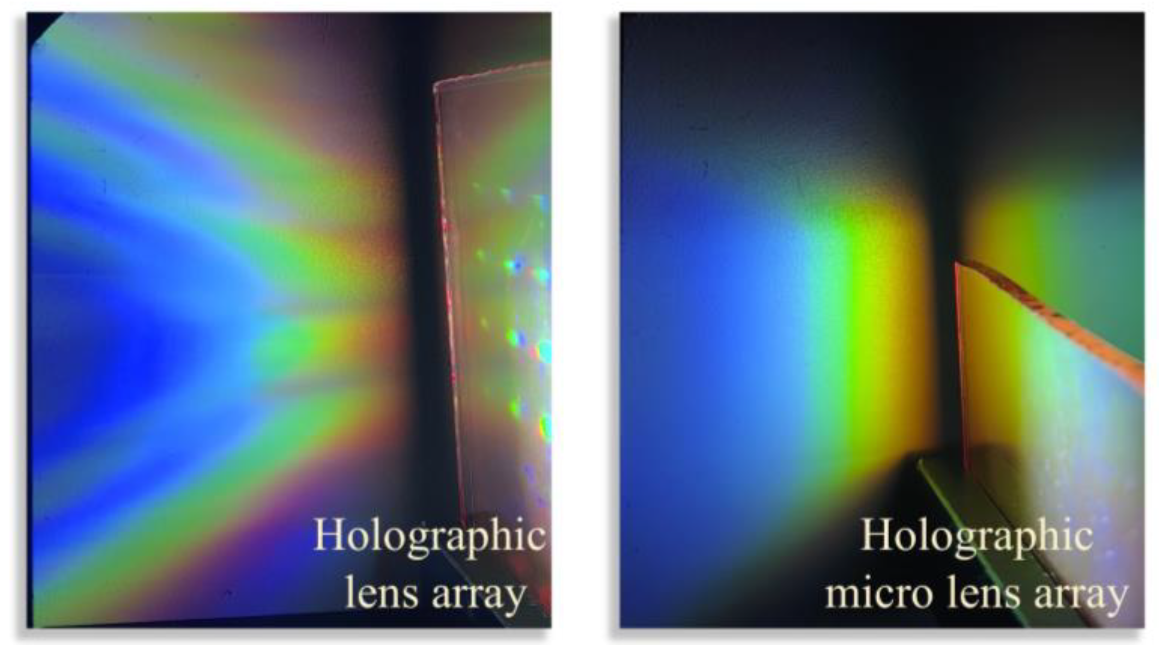
Due to some approximations in the design process, such as approximating spherical light as many parallel lights with multiple angles and ignoring the angle changes in diffraction light during variable wavelength reconstruction, there exists the phenomenon that the spatial distribution of the wide-spectrum diffraction light on the solar cell is uneven. This can be improved by changing the lens array used for fabricating the HLASC to a micro lens array. The comparison of the two effects is shown in Figure 7, where the left and right figures, respectively, show the collection light of an HLASC fabricated by a lens array and a micro lens array. The individual lens apertures of the lens array and micro lens array are 10 mm and 2 mm, respectively. It can be seen that the collection light of the HLASC fabricated by a micro lens array has a more uniform spatial distribution in the longitudinal direction, while it also has obvious spectral separation characteristics in the transverse direction, which gives us the opportunity to use solar cells with corresponding spectral bandgaps [30,31] to improve the photoelectric conversion efficiency. In addition, the reduction in OHL area also contributes to improving the color uniformity of the overall transmitted light of the HLASC, thereby expanding its application in see-through scenarios such as a holographic window.
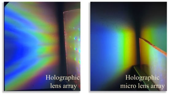
Figure 7.
Comparison of collection light of the HLASC fabricated by a lens array and a micro lens array.
There are still some interesting studies that can be conducted in the future. On the one hand, in order to further expand the collection angle, a multi-angle parallel light incident lens array offers a promising solution for recording the multiplexed HLASC. The subsequent testing of the HLASC under real-world irradiance conditions will also expand the collection of spectra beyond the visible light range. On the other hand, based on the principle of spectrum spatial allocation in this paper, by controlling the transmittance distribution of the lens array, it is theoretically possible to control the diffraction efficiency of different wavelengths, which helps to expand the application of HOE in blue light elimination, infrared light attenuation, and other fields. Finally, due to the spatial allocation of the collection spectrum, only a partial area of the HLASC can effectively collect light from a certain spectrum, resulting in a relatively low overall broad-spectrum collection efficiency of the HLASC. In the future, the collection efficiency can be further improved by cascading multiple layers of HOE.
5. Conclusions
This paper proposes a holographic lens array solar collector based on periodically arranged off-axis holographic lenses, which has both a large acceptance angle and a wide collection spectral width. Firstly, the holographic optical element has the advantages of being lightweight, flexible, and efficient. Secondly, the arrangement of off-axis collection brings more freedom to the design and can effectively reduce the area of solar cell, which is beneficial for improving the power to weight ratio and reducing costs. In addition, an HLASC with larger collection angles and spectral widths will also bring many benefits. On the one hand, a large acceptance angle contributes to the non-use of sun tracking equipment, ensuring that it is lightweight and portable while meeting the need for long-term collection. On the other hand, the spectral expansion method based on spectrum spatial allocation aids in improving energy collection and enhancing power supply efficiency. It is expected that the proposed design method for the HLASC could contribute to the development of compact and efficient solar collectors.
Author Contributions
Conceptualization, C.W. and J.L.; methodology, C.W., Y.X., H.X. and J.L.; software, C.W.; validation, C.W. and Y.X.; formal analysis, Y.X. and J.L.; investigation, C.W. and H.X.; resources, J.L.; data curation, C.W.; writing—original draft preparation, C.W.; writing—review and editing, C.W.; visualization, C.W. and Y.X.; supervision, J.L.; project administration, C.W. and Y.X.; funding acquisition, J.L. All authors have read and agreed to the published version of the manuscript.
Funding
This research was funded by the National Natural Science Foundation of China, grant number U22A2079 and 62035003; Beijing Municipal Science & Technology Commission, Administrative Commission of Zhongguancun Science Park, grant number Z211100004821012.
Institutional Review Board Statement
Not applicable.
Informed Consent Statement
Not applicable.
Data Availability Statement
The original contributions presented in the study are included in the article, and further inquiries can be directed to the corresponding author upon reasonable request.
Conflicts of Interest
The authors declare no conflicts of interest.
References
- Chemisana, D.; Collados, M.V.; Quintanilla, M.; Atencia, J. Holographic lenses for building integrated concentrating photovoltaics. Appl. Energy 2013, 110, 227–235. [Google Scholar] [CrossRef]
- Marín-Sáez, J.; Chemisana, D.; Atencia, J.; Collados, M.V. Outdoor performance evaluation of a holographic solar concentrator optimized for building integration. Appl. Energy 2019, 250, 1073–1084. [Google Scholar] [CrossRef]
- Zhou, B.C.; Pei, J.Z.; Nasir, D.M.; Zhang, J.P. A review on solar pavement and photovoltaic/thermal (PV/T) system. Transp. Res. Part D-Transp. Environ. 2021, 93, 102753. [Google Scholar] [CrossRef]
- Xue, J.L. Photovoltaic agriculture-New opportunity for photovoltaic applications in China. Renew. Sustain. Energy Rev. 2017, 73, 1–9. [Google Scholar] [CrossRef]
- Jia, L.M.; Ma, J.; Cheng, P.; Liu, Y.K. A Perspective on Solar Energy-powered Road and Rail Transportation in China. CSEE J. Power Energy 2020, 6, 760–771. [Google Scholar]
- Arancibia-Bulnes, C.A.; Peña-Cruz, M.I.; Mutuberría, A.; Díaz-Uribe, R.; Sánchez-González, M. A survey of methods for the evaluation of reflective solar concentrator optics. Renew. Sustain. Energy Rev. 2017, 69, 673–684. [Google Scholar] [CrossRef]
- Ghamari, M.; Sundaram, S. Solar Window Innovations: Enhancing Building Performance through Advanced Technologies. Energies 2014, 17, 3369. [Google Scholar] [CrossRef]
- Leutz, R.; Suzuki, A.; Akisawa, A.; Kashiwagi, T. Design of a nonimaging Fresnel lens for solar concentrators. Sol. Energy 1999, 65, 379–387. [Google Scholar] [CrossRef]
- Xie, W.T.; Dai, Y.J.; Wang, R.Z.; Sumathy, K. Concentrated solar energy applications using Fresnel lenses: A review. Renew. Sustain. Energy Rev. 2011, 15, 2588–2606. [Google Scholar] [CrossRef]
- Xu, N.; Ji, J.; Sun, W.; Huang, W.Z.; Li, J.; Jin, Z.L. Numerical simulation and experimental validation of a high concentration photovoltaic/thermal module based on point-focus Fresnel lens. Appl. Energy 2016, 168, 269–281. [Google Scholar] [CrossRef]
- Ludman, J.E. Holographic Solar Concentrator. Appl. Opt. 1982, 21, 3057–3058. [Google Scholar] [CrossRef]
- Kostuk, R.K.; Rosenberg, G. Analysis and Design of Holographic Solar Concentrators. In Proceedings of the High and Low Concentration for Solar Electric Applications III, 70430I, San Diego, CA, USA, 10–14 August 2008; Volume 7043. [Google Scholar]
- Collados, M.V.; Chemisana, D.; Atencia, J. Holographic solar energy systems: The role of optical elements. Renew. Sustain. Energy Rev. 2016, 59, 130–140. [Google Scholar] [CrossRef]
- Lee, J.H.; Wu, H.Y.; Piao, M.L.; Kim, N. Holographic Solar Energy Concentrator Using Angular Multiplexed and Iterative Recording Method. IEEE Photonics J. 2016, 8, 8400511. [Google Scholar] [CrossRef]
- Zhang, D.M.; Castro, J.M.; Kostuk, R.K. One-axis tracking holographic planar concentrator systems. J. Photon. Energy 2011, 1, 015505. [Google Scholar] [CrossRef]
- Kasezawa, T.; Horimai, H.; Tabuchi, H.; Shimura, T. Holographic window for solar power generation. Opt. Rev. 2016, 23, 997–1003. [Google Scholar] [CrossRef]
- Akbari, H.; Naydenova, I.; Martin, S. Using acrylamide-based photopolymers for fabrication of holographic optical elements in solar energy applications. Appl. Opt. 2014, 53, 1343–1353. [Google Scholar] [CrossRef]
- Akbari, H.; Naydenova, I.; Ahmed, H.; McCormack, S.; Martin, S. Development and testing of low spatial frequency holographic concentrator elements for collection of solar energy. Sol. Energy 2017, 155, 103–109. [Google Scholar] [CrossRef]
- Marín-Sáez, J.; Atencia, J.; Chemisana, D.; Collados, M.V. Full modeling and experimental validation of cylindrical holographic lenses recorded in Bayfol HX photopolymer and partly operating in the transition regime for solar concentration. Opt. Express 2018, 26, A398–A412. [Google Scholar] [CrossRef]
- Morales-Vidal, M.; Lloret, T.; Ramírez, M.G.; Beléndez, A.; Pascual, I. Green and wide acceptance angle solar concentrators. Opt. Express 2022, 30, 25366–25379. [Google Scholar] [CrossRef]
- Khan, A.A.; Yadav, H.L. Recording and analysis of off-axis multiplexed volume holographic lens for wavelength selective wide acceptance angle operation in concentrator photovoltaics. Opt. Eng. 2023, 62, 085130. [Google Scholar] [CrossRef]
- Morales-Vidal, M.; Lloret, T.; Nieto-Rodríguez, B.; García-Vázquez, J.C.; Berramdane, K.; Calzado, E.M.; Pascual, I. Development of high efficiency and wide acceptance angle holographic solar concentrators for breakthrough photovoltaic applications. In Proceedings of the Holography: Advances and Modern Trends VIII, 125740C, Prague, Czech Republic, 24–28 April 2023; Volume 12574. [Google Scholar]
- Lloret, T.; Morales-Vidal, M.; Nieto-Rodríguez, B.; García-Vázquez, J.C.; Beléndez, A.; Pascual, I. Building-Integrated Concentrating Photovoltaics based on a low-toxicity photopolymer. J. Phys. Energy 2024, 6, 015017. [Google Scholar] [CrossRef]
- Kao, H.X.; Ma, J.S.; Wang, C.C.; Wu, T.H.; Su, P. Crosstalk-reduced double-layer half-divided volume holographic concentrator for solar energy concentratio. Sensors 2020, 20, 6093. [Google Scholar] [CrossRef] [PubMed]
- Hung, J.; Chan, P.S.; Sun, C.M.; Ho, C.W.; Tam, W.Y. Doubly slanted layer structures in holographic gelatin emulsions: Solar concentrators. J. Opt. 2010, 12, 045104. [Google Scholar] [CrossRef]
- Vorndran, S.; Chrysler, B.; Kostuk, R.K. Comparison of holographic lens and filter systems for lateral spectrum splitting. In Proceedings of the Next Generation Technologies for Solar Energy Conversion VII, 99370K, San Diego, CA, USA, 28 August–1 September 2016; Volume 9937. [Google Scholar]
- Chrysler, B.D.; Wu, Y.C.; Yu, Z.S.; Kostuk, R.K. Volume holographic lens spectrum-splitting photovoltaic system for high energy yield with direct and diffuse solar illumination. In Proceedings of the Next Generation Technologies for Solar Energy Conversion VIII, 103680G, San Diego, CA, USA, 6–10 August 2017; Volume 10368. [Google Scholar]
- Chrysler, B.D.; Kostuk, R.K. High energy yield bifacial spectrum-splitting photovoltaic system. Appl. Opt. 2020, 59, G8–G18. [Google Scholar] [CrossRef]
- Wang, C.C.; Ma, J.S.; Kao, H.X.; Wu, T.H.; Su, P. Wide-band high concentration-ratio volume-holographic grating for solar concentration. Sensors 2020, 20, 6080. [Google Scholar] [CrossRef] [PubMed]
- Jarosz, G.; Marczynski, R.; Signerski, R. Effect of band gap on power conversion efficiency of single-junction semiconductor photovoltaic cells under white light phosphor-based LED illumination. Mater. Sci. Semicond. Process. 2020, 107, 104812. [Google Scholar] [CrossRef]
- Ranjan, R.; Ghosh, A.; Nirala, A.K.; Yadav, H.L. Tuning of suitable solar spectrum onto photocatalytic materials of the matched band gap using optical engineering. Opt. Appl. 2015, 45, 237–247. [Google Scholar]
Disclaimer/Publisher’s Note: The statements, opinions and data contained in all publications are solely those of the individual author(s) and contributor(s) and not of MDPI and/or the editor(s). MDPI and/or the editor(s) disclaim responsibility for any injury to people or property resulting from any ideas, methods, instructions or products referred to in the content. |
© 2025 by the authors. Licensee MDPI, Basel, Switzerland. This article is an open access article distributed under the terms and conditions of the Creative Commons Attribution (CC BY) license (https://creativecommons.org/licenses/by/4.0/).

