Abstract
Hydrogen is used as a fuel in various fields, such as aviation, space, and automobiles, due to its high specific energy. Hydrogen can be stored as a compressed gas at high pressure and as a liquid at cryogenic temperatures. In order to keep liquid hydrogen at a cryogenic temperature, the tanks for storing liquid hydrogen are required to have insulation to prevent heat leakage. When liquid hydrogen is vaporized by heat inflow, a large pressure is generated inside the tank. Therefore, a technology capable of predicting the tank pressure is required for cryogenic liquid hydrogen tanks. In this study, a thermodynamic model was developed to predict the maximum internal pressure and pressure behavior of cryogenic liquid hydrogen fuel tanks. The developed model considers the heat inflow of the tank due to heat transfer, the phase change from liquid to gas hydrogen, and the fuel consumption rate. To verify the accuracy of the proposed model, it was compared with the analyses and experimental results in the referenced literature, and the model presented good results. A cryogenic liquid hydrogen fuel tank was simulated using the proposed model, and it was confirmed that the storage time, along with conditions such as the fuel filling ratio of liquid hydrogen and the fuel consumption rate, should be considered when designing the fuel tanks. Finally, it was confirmed that the proposed thermodynamic model can be used to sufficiently predict the internal pressure and the pressure behavior of cryogenic liquid hydrogen fuel tanks.
1. Introduction
The development of eco-friendly fuels and renewable energies is attracting attention worldwide due to international interest and agreements to reduce carbon emissions in order to solve the global warming problem. In addition, as fossil fuels are currently the main global fuel source, they are expected to be depleted in the future, and thus it is necessary to reduce dependence on fossil fuels and to secure and develop new energy sources. There are many fuels that can replace fossil fuels, such as natural gas, biofuels [1,2], and synthetic fuels, but these fuels generate CO2 during combustion because they are also composed of carbon. Ammonia is a fuel that does not produce CO2 [3,4], but ammonia is highly toxic and has a pungent odor. Hydrogen is another fuel that does not generate CO2, and unlike ammonia, hydrogen is an odorless, colorless, and tasteless gas.
Since hydrogen has the advantage of having a higher specific energy than other fuels, it can be used in the transportation field. The specific energy of hydrogen is 120 MJ/kg, which is 2.8 times greater than that of fossil fuels (43.2 MJ/kg) [5,6]. Due to this advantage, hydrogen–oxygen was used as a propellent in the second stage of Saturn IB (S-IVB) in 1966 in the field of space launching [7], and launch vehicles using hydrogen are still being developed [8,9,10,11]. In the field of aviation, zero-carbon-emission future vehicles using hydrogen as fuel are being developed [12,13]. Airbus aims to develop zero-emission commercial aircraft that use hydrogen as a power source by 2035, and the company has proposed three concepts for such an aircraft [14]. As such, a lot of research and development is being conducted surrounding the use of hydrogen as a fuel in the transportation field. However, since hydrogen has a very low density at room temperature and atmospheric pressure, it has the disadvantage of requiring a lot of storage space to store an equivalent amount of energy as conventional fossil fuels [6,13,15]. For this reason, hydrogen requires storage methods different from fossil fuel storage methods. Therefore, research into hydrogen tanks for storing and supplying hydrogen as a fuel is required in order to use hydrogen as a power source.
The hydrogen fuel tank design method used depends on the type of hydrogen storage required. There are two methods of storing hydrogen: compressing it at high pressure, and liquefying it at a cryogenic temperature. Storing hydrogen gas at high pressure has the advantage of enabling it to be stored at room temperature. Gaseous hydrogen is usually stored at a pressure of 35 MPa (350 bar) [16] or 70 Mpa (700 bar) [17]. When compressed at high pressure, the density of hydrogen increases from 0.0852 kg/m3 at room temperature and atmospheric pressure to 23.995 kg/m3 at 35 Mpa and 40.172 kg/m3 at 70 Mpa. In order to store hydrogen gas at high pressure, the tank requires the application of structural design techniques that enable it to withstand the high pressure [18,19]. Thus, a disadvantage of high-pressure hydrogen tanks is that the weight of these tanks increases because they must withstand a very high pressure.
Hydrogen can be liquefied when cooled to cryogenic temperatures and stored in a liquid state. The liquefaction temperature of hydrogen is −252.78 °C (20.37 K) at atmospheric pressure. Liquid hydrogen tanks require insulated designs [20,21] to prevent loss to vaporization since liquid hydrogen is vaporized into a gas by external heat inflow. However, no matter how excellent the insulation performance of the tank is, liquid hydrogen is vaporized by heat inflow. When liquid hydrogen is vaporized, its specific volume expands approximately 53 times from 0.0141 m3/kg to 0.7507 m3/kg at atmospheric pressure. The internal pressure of the tank increases when liquid hydrogen is vaporized inside the tank [22,23]. Therefore, it is necessary to predict the tank pressure due to the vaporization of liquid hydrogen in order to design the structure of cryogenic liquid hydrogen tanks.
The maximum storage pressure of the tank is one of the important considerations in the structural design of a hydrogen fuel tank. The design of gaseous hydrogen tanks is relatively simple because the design pressure is determined at the beginning of the design. In contrast, the design of a cryogenic liquid hydrogen tank is complicated by additional factors. These design considerations include the tank shape, the insulation performance, the amount of liquid hydrogen filling, and the fuel consumption rate. These considerations affect the maximum pressure and pressure behavior of the liquid hydrogen tank. The structures and the insulation area are changed according to the shape of tank. The insulation performance of the tank affects the amount of vaporized liquid hydrogen and the pressure inside the tank. In addition, the maximum pressure of the tank varies according to the amount of liquid hydrogen stored in the tank [24], and the fuel consumption rate affects the pressure behavior [25,26]. Therefore, in designing a liquid hydrogen fuel tank, a technique for predicting the maximum internal pressure that considers the heat inflow, liquid hydrogen filling amount, and fuel consumption rate is required.
This study aims to develop a thermodynamic model that can predict the maximum internal pressure and pressure behavior of cryogenic liquid hydrogen tanks. The heat leakage of the tank by heat transfer is applied by dividing it into a liquid area and a gaseous area. The thermodynamic model considers the phase change from liquid hydrogen to gaseous hydrogen [27,28], and estimates the temperature and pressure in the gas region. The analysis is performed as a transient analysis. The tank pressure behavior depends on fuel discharge and is investigated by selecting a commercial fuel cell to calculate the fuel consumption rate. The analysis of the cryogenic liquid hydrogen tank is carried out for three cases: without fuel consumption (storage tank), with fuel consumption immediately after liquid hydrogen filling, and with time delay before fuel consumption after fuel charging. Finally, the prediction accuracy and applicability of the proposed thermodynamic model are confirmed.
2. Thermodynamic Model
A cryogenic fuel tank consists of a tank structure, insulation, and fuel. External heat is transferred to the inside of the tank via the tank structure and insulation. The heat flow rate depends on the shape of the tank, the thickness of the tank structure, and the insulation [20,21]. In addition, the insulation performance of the tank varies depending on the materials used in the structure and the insulation, because the thermal conductivity of materials varies. Cryogenic fuel exists as a mixture of liquid and gaseous phases inside the tank. The liquid fuel undergoes a phase change into a gas by the heat inflow from the outside of the tank. The gas vaporized due to the heat inflow increases the temperature and the pressure inside the tank. The tank pressure is reduced when the fuel is supplied to a fuel consumption device, such as fuel cell, or discharged to the outside, acting as pressure relief. Therefore, a thermodynamic model for a cryogenic fuel tank needs to be developed to consider the amount of heat transfer through the structure, the filling ratio of liquid fuel, the phase change, and the fuel consumption rate.
A thermodynamic phenomenon occurring in the cryogenic fuel tank can be expressed in a schematic diagram, as shown in Figure 1. Several assumptions were made to develop the thermodynamic model. First, it was assumed that the heat introduced from the outside of the tank is transferred to the liquid and gas regions separately [29,30]. This can be expressed as Equations (1) and (2).
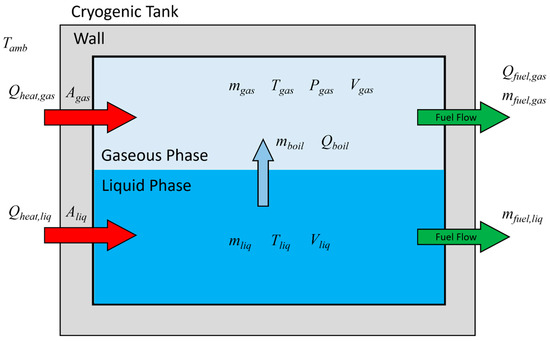
Figure 1.
Schematic illustration of the thermodynamic model for cryogenic tanks.
In applying the overall heat transfer coefficient between the outside and inside of the tank, convection by ambient air was not considered, in order to ignore the influence of the convective environment outside the tank. In addition, it was assumed that sufficient convection occurs within gaseous and liquid hydrogen [31] through boil-off and fuel emission flow. Therefore, Equations (3) and (4) are simplified to Equation (5), in which only the terms due to heat conduction are considered.
Second, the heat introduced into the liquid region is used to vaporize the liquid. The mass corresponding to the vaporization energy of the liquid is transferred to the gas region. The vaporized mass flow is calculated as in Equation (6).
The differential mass in the liquid and gas regions by the vaporized mass flow is expressed as Equations (7) and (8).
Lastly, the heat introduced into the gas region only changes the temperature and pressure of the gas. The condensation caused by the rise in gas pressure was not considered. Hence, the mass only moves from the liquid region to the gas region.
In the case of using fuel, the fuel may be supplied in a gaseous or liquid form or both. When discharge of fuel from the tank to the outside occurs, the fuel consumption term is added to Equations (7) and (8), and expressed as Equations (9) and (10).
The differential heat energy of the gas region consists of the heat energy transferred from the outside, the heat added by vaporized hydrogen from liquid hydrogen, and the heat lost from being used as fuel. It is expressed as Equation (11).
The work energy relating to the volume expansion of the gaseous region due to the discharged hydrogen and the vaporized liquid hydrogen is calculated by Equation (12). The differential volume dVexpand is the sum of the volumes of the vaporized liquid hydrogen and the discharged fuels. The differential of the internal energy in the gaseous region is expressed as the sum of the differential heat and work energies, as in Equation (13). The differential temperature of the gas is estimated using the heat capacity equation, Equation (14).
Finally, the tank pressure is calculated by the ideal gas equation of state using the recalculated temperature, volume, and mass of the gaseous region.
3. Validation of Thermodynamic Model
The validation of the proposed thermodynamic model was carried out by dividing it into a vaporization model of liquid hydrogen and a fuel emission model. The vaporization model was verified by referring to the data of Liu et al. [32] in Section 3.1. The fuel emission model was verified by referring to the data of Miguel et al. [33] in Section 3.2. Consequently, the proposed model predicted well the gas temperature and the tank pressure, showing a relative error within 1% for the vaporization model of liquid hydrogen, and within 8.7% for the fuel emission model.
3.1. Validation of Evaporation Model
Validation of the proposed model for liquid hydrogen vaporization was performed with the tank model and analysis results of Liu et al. [32]. The tank had a cylindrical shape with a radius of 0.5 m and a height of 2.0 m. Liquid hydrogen was contained at a height of 1.0 m in the tank, and gaseous hydrogen filled in the remaining area of the tank. The temperature of the liquid hydrogen was 21 K, the temperature of the gaseous hydrogen was 24 K, and the pressure was 150 kPa. A heat flux of 10 W/m2 was transferred uniformly through the tank body.
To verify the prediction accuracy of the proposed model, the temperature and pressure analysis results of the gas area were compared. Figure 2 displays the results of the temperature and the pressure. The black solid line is the result of the present model, and the red open circle is the data from the reference. Figure 2a shows that the temperature increased as the heat inflow occurred. The gas temperature of the present model was slightly lower than that of the reference data at the end of the measured period, and the maximum relative error was 0.73%. The present analysis result for pressure represents a very similar value to that of the reference; as shown in Figure 2b, the relative error was calculated as within 0.44%. Thus, both results produced a very slight difference of less than 0.8% relative error. The developed model predicted temperature and pressure changes well due to heat inflow and boil-off, even though it did not consider the convection coefficient inside the tank. Therefore, it can be said that the present model produced very good results.
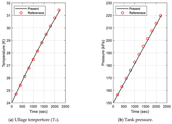
Figure 2.
Comparison of ullage temperature and tank pressure for evaporation model validation.
3.2. Validation of Fuel Emission Model
Validation of the proposed model for fuel emission was performed with the tank model and experimental results of Miguel et al. [33]. The tank had an outer diameter of 329 mm, an inner diameter of 290 mm, a length of 920 mm, and a volume of 40 L. The initial pressure of the filled tank was 70 MPa. The average mass flow rate discharged to the outside of tank was 1.8 g/s. The gas temperature was measured at six points inside the tank. The internal pressure was measured with one pressure sensor.
To verify the prediction accuracy of the proposed model for fuel emission, the temperature and pressure analysis results for the gas area were compared. When gas was discharged from the pressurized tank, the pressure was naturally reduced, and the temperature was decreased because the gas expanded by the volume at which it was released. This phenomenon was also observed in the temperature and pressure prediction results, as shown in Figure 3. In the figure, the black solid line is the present analysis result, and the red open circle represents the experimental data of the reference. Figure 3a shows that the temperature decreased as the gas was discharged. The gas temperature of the present model was lower than that of the reference data, and the relative error was within 7.75%. The pressure of the present analysis result represented a higher value, as shown in Figure 3b. The relative error was calculated as being within 9.78%. The error of pressure was relatively large compared to the error of temperature. This is thought to be due to the use of the ideal gas equation of state when calculating the pressure over a wide range of pressures. In order to increase the accuracy of the analysis result, it is necessary to modify this part to include a realistic formula. Despite the assumption of an ideal gas, it can be said that the present analysis model produced very good results.
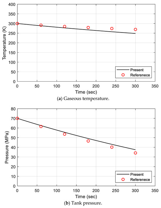
Figure 3.
Comparison of gaseous temperature and tank pressure for defueling model validation.
4. Analysis of Cryogenic Fuel Tanks
4.1. Analysis Condition
The fuel consumption rate was calculated for the analysis of the cryogenic liquid hydrogen tank. The fuel consumption device for calculating the fuel consumption rate was selected to be a PROTIUM-300 [34] fuel cell, made by Spectronik Pte. Ltd., Singapore. The selected fuel cell produced a rated power of 300 W when the fuel consumption rate was 3.8 L/min. The hydrogen supply conditions were a temperature of 24 °C and a pressure of 140 kPa to 170 kPa. When the fuel consumption rate was recalculated by applying the hydrogen supply conditions, it became 7.229 × 10⁻³ g/s to 8.776 × 10⁻³ g/s. In the present analysis, the lower fuel consumption rate of 7.229 × 10⁻³ g/s was applied to predict the maximum pressure of the tank.
The size of the fuel tank was set so that the fuel cell could be loaded with enough fuel to operate for one hour. As shown in Figure 4, the tank was cylindrical, and it had a diameter (D) of 80 mm and a height (H) of 120 mm. Liquid hydrogen filled 80% of the tank volume, and the remainder was filled with gaseous hydrogen at a pressure of 150 kPa. The mass of hydrogen contained in the tank was 33.857 g of liquid hydrogen and 0.201 g of gaseous hydrogen, which was a total of 34.055 g. This could supply the fuel cell for more than one hour, based on the maximum fuel consumption rate.
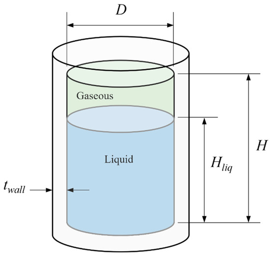
Figure 4.
Geometry of cryogenic liquid fuel tank.
The heat transfer of the tank was considered to be the heat conduction through the tank wall. The ambient temperature was set at 15 °C. The structural thickness of the tank was ignored because it was very thin and its materials had a higher thermal conductivity compared to the insulation. The thickness of the insulator was set to 60 mm. The thermal conductivity of the insulator was applied as 0.037 W/m∙K.
4.2. Analysis Results
The transient analysis was performed with respect to the analysis conditions. The analysis was conducted for three cases: (1) storage without fuel emission after fuel charging, (2) fuel consumption immediately after fuel charging, and (3) 30 min delay before fuel consumption after refueling.
The first case was a scenario in which fuel was stored without fuel emission after fuel charging. The total mass of hydrogen inside the tank remained constant, as shown in Figure 5a, because hydrogen was not discharged to the outside. The dotted line represents the total mass of hydrogen inside the tank, the blue solid line represents the mass of liquid hydrogen, and the red solid line shows the mass of gaseous hydrogen. The mass of liquid hydrogen decreased over time because it was vaporized by heat transferred from the outside of the tank. The mass of gaseous hydrogen was increased by the mass of vaporized liquid hydrogen. The temperature of gaseous hydrogen rose due to heat transfer from the outside, as displayed in Figure 5b. The pressure in the tank increased rapidly, as shown in Figure 5c, because the specific volume of the vaporized hydrogen was much larger than that of liquid hydrogen. The pressure was 7.62 MPa when the storage time reached 30 min, and 12.0 MPa when the storage time reached 1 h.
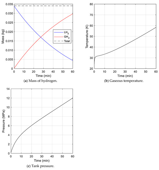
Figure 5.
Analysis results for cryogenic fuel tank without fuel consumption.
The second case reflected a scenario of fuel consumption immediately after fuel charging. In this case, the total mass of hydrogen inside the tank was constantly reduced, as shown in Figure 6a, because hydrogen was discharged to the outside at a constant fuel consumption rate. The change in the mass of liquid hydrogen in the tank displayed behavior similar to that seen in case 1. The mass of gaseous hydrogen increased at the beginning, and then decreased. This was because the amount of heat transferred to the liquid hydrogen gradually decreased. When the amount of liquid hydrogen was reduced, the heat transfer area of the liquid hydrogen was decreased, and thus, the amount of vaporization eventually decreased. The gaseous temperature was higher than that of case 1, as shown in Figure 6b, because the mass of hydrogen in the gas region was reduced (i.e., the density of the gas region was reduced) due to fuel consumption. However, the tank pressure was increased initially and then gradually decreased, as represented in Figure 6c, as gaseous hydrogen was continuously discharged to the outside. The pressure reached a maximum of 2.30 MPa at about 37 min.
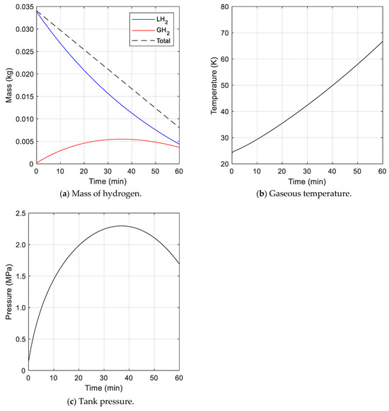
Figure 6.
Analysis results for cryogenic fuel tank with fuel consumption.
The final cases (case 3) represented scenarios of 5 min (case 3a), 10 min (case 3b), and 30 min (case 3c) delays before fuel consumption after fuel charging. In these cases, the initial 5, 10, and 30 min after charging showed the same behavior as in case 1 when there was no fuel emission. After that, as fuel consumption started, differences appeared in the mass, temperature, and pressure behavior. As shown in Figure 7a, the mass of gaseous hydrogen in cases 3a and 3b increased as fuel consumption began. On the contrary, in case 3c, it gradually reduced. This was because the evaporation of liquid hydrogen occurred consistently regardless of delayed time, and the amount of evaporation decreased as time passes.
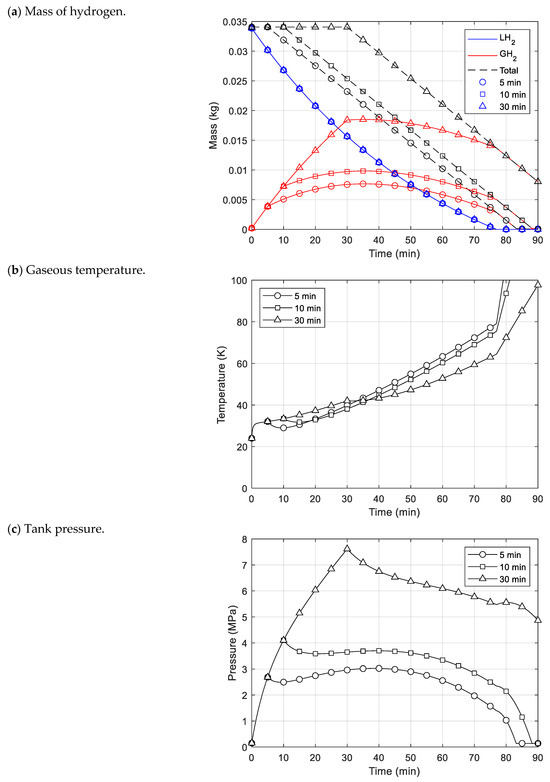
Figure 7.
Analysis results for cryogenic fuel tank with delay time before fuel consumption.
The temperature of the gaseous hydrogen slightly decreased as fuel consumption began, but it is soon rose again, as represented in Figure 7b. As the fuel was discharged out of the tank, the internal gas expanded and the temperature dropped, but it appeared to have increased due to heat inflow. The temperature increased rapidly from about 77 min onwards, at which point the liquid hydrogen was fully evaporated. This was because the heat that expanded to vaporize the liquid hydrogen also raised the gaseous temperature, and the mass of gaseous hydrogen inside the tank was reduced due to fuel consumption. For this reason, the temperature elevated rapidly during this period.
The tank pressure behaviors as fuel consumption began were similar to the temperature behaviors, as displayed in Figure 7c. The pressure dropped initially, but the pressure in cases 3a and 3b rose gradually because the mass and temperature of the gaseous hydrogen increased. In cases 3b and 3c, the maximum pressure occurred just before fuel consumption began. In contrast, the maximum pressure point of case 3a occurred at a similar time as in case 2, reaching a maximum of 3.03 MPa at about 39 min.
Comparing these cases, case 2, in which fuel consumption occurred immediately after filling the tank with liquid hydrogen, had smaller pressure values compared to the delayed cases. However, in reality, cryogenic fuel tanks are operated in a way that reflects the delayed cases, as it takes time to begin fuel consumption after fuel charging. In case 3c, the pressure rapidly decreased from the maximum after fuel consumption started, but in the other delayed cases, the pressure increased again. In all of the delayed cases, the maximum pressure was higher than in case 2. For this reason, the delay time before fuel consumption after fuel filling, along with the fuel consumption rate, should be considered as important factors in predicting the maximum pressure of a cryogenic fuel tank. Additionally, this indicates that there could be a large difference in the maximum pressure inside different tanks depending on various operating factors, and a model that quickly and accurately predicts this is needed.
Therefore, using the present thermodynamic model developed in this study, it is possible to rapidly predict the maximum pressure and the pressure behavior of a cryogenic liquid hydrogen fuel tank under these conditions.
5. Conclusions
A thermodynamic model was developed to predict the maximum internal pressure of cryogenic liquid hydrogen fuel tanks. The proposed model considers the phase change from liquid to gas hydrogen due to heat transfer from the outside of the tank. The model can perform a transient analysis by applying the fuel consumption rate. The accuracy of the model was verified by dividing it into cases of storing liquid hydrogen and discharging hydrogen to the outside. The proposed model presented good results.
The pressure in the tank becomes smallest when fuel is consumed immediately after liquid hydrogen fills the tank. However, in the actual operation of a cryogenic fuel tank, a time delay occurs between the completion of charging and the consumption of fuel. Since the behavior of the pressure can be greatly affected by this delay time, it must be taken into account as a major consideration when designing cryogenic liquid hydrogen fuel tanks. The proposed model can consider the operating conditions of fuel tanks. Therefore, it can be concluded that the proposed thermodynamic model is sufficiently usable for predicting the maximum internal pressure and the pressure behavior of cryogenic liquid hydrogen fuel tanks.
Author Contributions
Methodology, D.C.; Validation, D.C.; Formal analysis, D.C.; Writing—original draft, D.C.; Writing—review & editing, S.L. and S.K. All authors have read and agreed to the published version of the manuscript.
Funding
This research was supported by the Basic Science Research Program through the National Research Foundation of Korea (NRF), funded by the Ministry of Education (No. 2022R1A6A1A03056784), and this work was also supported by the ‘Space Pioneer Program’ grant funded by the Ministry of Science and ICT, Republic of Korea (No. 2021M1A3B9096764).
Institutional Review Board Statement
Not applicable.
Informed Consent Statement
Not applicable.
Data Availability Statement
The raw data supporting the conclusions of this article will be made available by the authors on request.
Conflicts of Interest
The authors declare that they have no conflicts of interest.
Nomenclature
| Agas | Heat transfer area of gas region (m2) |
| Aliq | Heat transfer area of liquid region (m2) |
| C | Specific heat (J/kg∙K) |
| dt | Differential time (s) |
| hamb | Convection coefficient of tank outside (W/m2∙K) |
| hgas | Convection coefficient of gas region (W/m2∙K) |
| hliq | Convection coefficient of liquid region (W/m2∙K) |
| hwall,gas | Total heat transfer coefficient of gas region (W/m2∙K) |
| hwall,liq | Total heat transfer coefficient of liquid region (W/m2∙K) |
| hfg | Latent heat of vaporization (J/kg) |
| kwall | Conduction coefficient of wall (W/m2∙K) |
| Lwall | Wall thickness (m) |
| Pgas | Gas pressure (Pa) |
| qboil | Heat transfer rate by boil-off (W) |
| qheat,gas | Heat transfer rate by gas region (W) |
| qheat,liq | Heat transfer rate by liquid region (W) |
| qfuel,gas | Heat transfer rate by gas fuel (W) |
| Qgas | Energy transfer of gas (J) |
| Tamb | Ambient temperature (K) |
| Tgas | Gas temperature (K) |
| Tliq | Liquid temperature (K) |
| Vgas | Volume of gas (m3) |
| Vliq | Volume of Liquid (m3) |
| Vexpand | Virtual expanded volume by fuel consumption (m3) |
| mgas | Mass of gas (kg) |
| mliq | Mass of liquid (kg) |
| Boil-off mass flow rate (kg/s) | |
| Gas fuel flow rate (kg/s) | |
| Liquid fuel flow rate (kg/s) | |
| Ugas | Internal energy of gas (J) |
| Wgas | Work energy of gas (J) |
References
- Arun, J.; Gopinath, K.P.; Sivaramakrishnan, R.; SundarRajan, P.; Malolan, R.; Pugazhendhi, A. Technical insights into the production of green fuel from CO2 sequestered algal biomass: A conceptual review on green energy. Sci. Total Environ. 2021, 755, 142636. [Google Scholar] [CrossRef] [PubMed]
- Seyam, S.; Dincer, I.; Agelin-Chaab, M. Novel hybrid aircraft propulsion systems using hydrogen, methane, methanol, ethanol and dimethyl ether as alternative fuels. Energy Convers. Manag. 2021, 238, 114172. [Google Scholar] [CrossRef]
- Valera-Medina, A.; Amer-Hatem, F.; Azad, A.K.; Dedoussi, I.C.; de Joannon, M.; Fernandes, R.X.; Glarborg, P.; Hashemi, H.; He, X.; Mashruk, S.; et al. Review on Ammonia as a Potential Fuel: From Synthesis to Economics. Energy Fuels 2021, 35, 6964–7029. [Google Scholar] [CrossRef]
- Jeerh, G.; Zhang, M.; Tao, S. Recent progress in ammonia fuel cells and their potential applications. J. Mater. Chem. A 2021, 9, 727–752. [Google Scholar] [CrossRef]
- Nojoumi, H.; Dincer, I.; Naterer, G. Greenhouse gas emissions assessment of hydrogen and kerosene-fueled aircraft propulsion. Int. J. Hydrogen Energy 2009, 34, 1363–1369. [Google Scholar] [CrossRef]
- Khandelwal, B.; Karakurt, A.; Sekaran, P.R.; Sethi, V.; Singh, R. Hydrogen powered aircraft: The future of air transport. Prog. Aerosp. Sci. 2013, 60, 45–59. [Google Scholar] [CrossRef]
- Vietze, M.; Mundt, C.; Weiland, S. Investigation of Thermal Characteristics of Sandwich Common Bulkhead Equipped Launcher Tank. J. Spacecr. Rocket. 2017, 54, 67–74. [Google Scholar] [CrossRef]
- Szelinski, B.; Lange, H.; Röttger, C.; Sacher, H.; Weiland, S.; Zell, D. Development of an innovative sandwich common bulkhead for cryogenic upper stage propellant tank. Acta Astronaut. 2012, 81, 200–213. [Google Scholar] [CrossRef]
- Sumith, S.; Kumar, R.R. Thermo-structural analysis of cryogenic tanks with common bulkhead configuration. Proc. Inst. Mech. Eng. Part G J. Aerosp. Eng. 2022, 236, 900–909. [Google Scholar] [CrossRef]
- Schweickart, R.B. Thermodynamic analysis of a demonstration concept for the long-duration storage and transfer of cryogenic propellants. Cryogenics 2014, 64, 283–288. [Google Scholar] [CrossRef]
- Liu, N.; Ma, B.; Liu, F.; Huang, W.; Xu, B.; Qu, L.; Yang, Y. Progress in research on composite cryogenic propellant tank for large aerospace vehicles. Compos. Part A Appl. Sci. Manuf. 2021, 143, 106297. [Google Scholar] [CrossRef]
- Verstraete, D. Long range transport aircraft using hydrogen fuel. Int. J. Hydrogen Energy 2013, 38, 14824–14831. [Google Scholar] [CrossRef]
- Huete, J.; Pilidis, P. Parametric study on tank integration for hydrogen civil aviation propulsion. Int. J. Hydrogen Energy 2021, 46, 37049–37062. [Google Scholar] [CrossRef]
- Airbus. Airbus Reveals New Zero-Rmission Concept Aircraft. 2020. Available online: https://www.airbus.com/en/newsroom/press-releases/2020-09-airbus-reveals-new-zero-emission-concept-aircraft (accessed on 12 June 2023).
- Huete, J.; Nalianda, D.; Pilidis, P. Propulsion system integration for a first-generation hydrogen civil airliner? Aeronaut. J. 2021, 125, 1654–1665. [Google Scholar] [CrossRef]
- Romeo, G.; Borello, F.; Correa, G.; Cestino, E. ENFICA-FC: Design of transport aircraft powered by fuel cell & flight test of zero emission 2-seater aircraft powered by fuel cells fueled by hydrogen. Int. J. Hydrogen Energy 2013, 38, 469–479. [Google Scholar] [CrossRef]
- Zhang, Q.; Xu, H.; Jia, X.; Zu, L.; Cheng, S.; Wang, H. Design of a 70 MPa type IV hydrogen storage vessel using accurate modeling techniques for dome thickness prediction. Compos. Struct. 2020, 236, 111915. [Google Scholar] [CrossRef]
- Leh, D.; Saffré, P.; Francescato, P.; Arrieux, R.; Villalonga, S. A progressive failure analysis of a 700-bar type IV hydrogen com-posite pressure vessel. Int. J. Hydrog. Energy 2015, 40, 13206–13214. [Google Scholar] [CrossRef]
- Sharma, P.; Bera, T.; Semwal, K.; Badhe, R.M.; Sharma, A.; Ramakumar, S.; Neogi, S. Theoretical analysis of design of filament wound type 3 composite cylinder for the storage of compressed hydrogen gas. Int. J. Hydrogen Energy 2020, 45, 25386–25397. [Google Scholar] [CrossRef]
- Joseph, J.; Agrawal, G.; Agarwal, D.K.; Pisharady, J.; Kumar, S.S. Effect of insulation thickness on pressure evolution and thermal stratification in a cryogenic tank. Appl. Therm. Eng. 2017, 111, 1629–1639. [Google Scholar] [CrossRef]
- Zheng, J.; Chen, L.; Wang, J.; Xi, X.; Zhu, H.; Zhou, Y.; Wang, J. Thermodynamic analysis and comparison of four insulation schemes for liquid hydrogen storage tank. Energy Convers. Manag. 2019, 186, 526–534. [Google Scholar] [CrossRef]
- Zhou, R.; Zhu, W.; Hu, Z.; Wang, S.; Xie, H.; Zhang, X. Simulations on effects of rated ullage pressure on the evaporation rate of liquid hydrogen tank. Int. J. Heat Mass Transf. 2019, 134, 842–851. [Google Scholar] [CrossRef]
- Yang, H.Q.; Patel, C.; Williams, B. Validation of Cryogenic Propellant Tank Self-Pressurization. In Proceedings of the AIAA SciTech Forum, National Harbor, MD, USA, 23–27 January 2023. [Google Scholar]
- Zuo, Z.; Jiang, W.; Qin, X.; Huang, Y. A numerical model for liquid–vapor transition in self-pressurized cryogenic containers. Appl. Therm. Eng. 2021, 193, 117005. [Google Scholar] [CrossRef]
- Wang, L.; Ma, Y.; Wang, Y.; Xie, F.; Li, Y. Investigation on pressurization behaviors of two-side-insulated cryogenic tank during discharge. Int. J. Heat Mass Transf. 2016, 102, 703–712. [Google Scholar] [CrossRef]
- Ahluwalia, R.; Peng, J. Dynamics of cryogenic hydrogen storage in insulated pressure vessels for automotive applications. Int. J. Hydrogen Energy 2008, 33, 4622–4633. [Google Scholar] [CrossRef]
- Jiang, Y.; Yu, Y.; Wang, Z.; Zhang, S.; Cao, J. CFD simulation of heat transfer and phase change characteristics of the cryogenic liquid hydrogen tank under microgravity conditions. Int. J. Hydrogen Energy 2023, 48, 7026–7037. [Google Scholar] [CrossRef]
- Fu, J.; Sunden, B.; Chen, X.; Huang, Y. Influence of phase change on self-pressurization in cryogenic tanks under microgravity. Appl. Therm. Eng. 2015, 87, 225–233. [Google Scholar] [CrossRef]
- Liu, Z.; Li, Y. Thermal physical performance in liquid hydrogen tank under constant wall temperature. Renew. Energy 2019, 130, 601–612. [Google Scholar] [CrossRef]
- Wang, H.; Wang, B.; Pan, Q.; Wu, Y.; Jiang, L.; Wang, Z.; Gan, Z. Modeling and thermodynamic analysis of thermal performance in self-pressurized liquid hydrogen tanks. Int. J. Hydrogen Energy 2022, 47, 30530–30545. [Google Scholar] [CrossRef]
- Ho, S.H.; Rahman, M.M. Forced convective mixing in a zero boil-off cryogenic storage tank. Int. J. Hydrogen Energy 2012, 37, 10196–10209. [Google Scholar] [CrossRef]
- Liu, Z.; Wang, L.; Jin, Y.; Li, Y. Development of thermal stratification in a rotating cryogenic liquid hydrogen tank. Int. J. Hydrogen Energy 2015, 40, 15067–15077. [Google Scholar] [CrossRef]
- de Miguel, N.; Acosta, B.; Moretto, P.; Cebolla, R.O. The effect of defueling rate on the temperature evolution of on-board hydrogen tanks. Int. J. Hydrogen Energy 2015, 40, 14768–14774. [Google Scholar] [CrossRef]
- Spectronik Pte. Ltd. PROTIUM-300 Fuel Cell System User Guide Version 5.0. 2022. Available online: https://www.spectronik.com/protium-300 (accessed on 12 June 2023).
Disclaimer/Publisher’s Note: The statements, opinions and data contained in all publications are solely those of the individual author(s) and contributor(s) and not of MDPI and/or the editor(s). MDPI and/or the editor(s) disclaim responsibility for any injury to people or property resulting from any ideas, methods, instructions or products referred to in the content. |
© 2024 by the authors. Licensee MDPI, Basel, Switzerland. This article is an open access article distributed under the terms and conditions of the Creative Commons Attribution (CC BY) license (https://creativecommons.org/licenses/by/4.0/).