Abstract
Molecular dynamics simulations were performed on CaO-MgO-Al2O3-SiO2 (CMAS) diopside glass ceramics (GCs) to study the effect of nanocrystal on glass and the effect of chemical composition on mechanical properties. Under tensile loading, the GCs demonstrated that the strength lay between its glass and ceramic counterparts and maintained considerable ductility. Moreover, high Mg/Ca ion ratios are conductive to both the strength and ductility of GCs. In addition, Al ions should be avoided as far as possible since they would promote fracture. After analyzing the shear strain and displacement vector map for ion structures, we found that the presence of nanocrystal in glass changes the original deformation pattern and led to the deformation concentration surrounding the nanocrystal. A high Mg/Ca ion ratio would make the deformation more homogeneous, while a high Ca/Mg ion ratio would aggregate the deformation in the glass region near the nanocrystal. The existence of Al ions near the interface between glass and crystal would promote the formation of voids.
1. Introduction
Glass ceramics (GCs) are relatively new materials created by the partial crystallization of glass at a carefully controlled temperature [1,2]. Therefore, GCs are inorganic and non-metallic materials with both glassy and crystalline phases. Because of the presence of crystalline phases in the residual and continuous glassy phases, GCs have a variety of unusual mechanical, electrical, optical and magnetic properties, which make GCs widely used in industrial areas such as architecture, building, optics, electronics and domestics [1,3,4,5]. Among these features, the superior mechanical properties are significant since the crystalline phase in GCs can contribute strength and the glassy phase can offer ductility [6,7]. Furthermore, through the control of the chemical composition, crystal size and thermal treatment, the mechanical properties can also be modified significantly [8,9,10,11].
There are various types of GCs. One common classification method is based on the composition and crystalline structure, such as for silicate GCs, phosphate GCs and borate GCs. CaO-MgO-Al2O3-SiO2 (CMAS) glass is an important system to produce GCs owing to easy access to their natural raw materials [12,13]. As the CMAS system is a quaternary system with a complicated phase diagram, there are vast different crystalline structures that can be nucleated by adjusting the temperature and composition. Some common and important crystalline phases nucleated in the CMAS system are diopside (CaO·MgO·2SiO2), anorthite (CaO·Al2O3·2SiO2) and cordierite (2MgO·2Al2O3·5SiO2) and most of these crystalline phases have chemical stability [14]. Among these crystalline phases, the diopside phase can make the CMAS GCs have superior mechanical properties compared to others, which makes the diopside GCs have a wide range of applications [3,15,16,17,18]. Moreover, the CaO-MgO-SiO2 glass systems (CMS) are shown to have high biocompatibility and bioactivity and stimulate new bone growth [15,16,17,19]. So, the diopside GCs have become an ideal candidate in the biomedical domain.
The mechanical properties of diopside GCs in the CMAS system can be controlled by many factors, such as the temperature, chemical composition, nucleating agents, crystal size, etc. [3,15,17]. Most previous works have focused on the effect of the sintering temperature and the addition of various nucleation agents, such as ZrO2, B2O3 and P2O5 [3,20,21]. To make the diopside GCs work well in biomedical applications, it is necessary to systematically evaluate the strength and fracture toughness, so that they can fit as closely as possible with the corresponding biological tissues, such as cortical bone, trabecular bone and dentine [22,23]. The nucleation agent, sintering temperature and crystal size can significantly influence the production and morphologies of GCs, while the composition of the CMAS glass phase can also affect the mechanical properties, such as the strength and fracture toughness. However, it is by no means a trivial task since the composition effect with a wide range of variable space using an experimental approach is usually time-consuming and expensive. Moreover, the in situ capture of the crack propagation events in GCs is extremely challenging using traditional SEM and TEM approaches and the important atomic details may also be neglected.
As an alternative approach to experiments, atomistic simulation can offer some unique capabilities for observing the atomic structures of glass, crystals and their interface, providing insights into the complex deformation mechanism involved in the strength and fracture properties [24]. However, the atomistic simulations on GCs are extremely limited in the existing literature. Only in the past few years has molecular dynamics (MD) simulation been used to study the crack propagation and fracture resistance of LiO-Al2O3-SiO2 (LAS) GCs [25,26]. These atomistic simulation works elucidating the fracture mode and crack propagation pattern are in good agreement with the in situ experiment observations [25]. The recent progress demonstrates that MD simulation may also be helpful in studying the mechanical properties and deformation mechanisms in diopside GCs.
In this work, we conducted MD simulation to study diopside GCs and the effect of glass chemical composition on the mechanical properties (strength and ductility). Because of the extremely small simulation time step, the nucleation and sintering processes were nearly impossible to investigate using the MD simulation, so we directly constructed the diopside GCs model with different glass phase compositions. We performed tension loading simulations to investigate the strength using a strain–stress curve and the atomistic structure evolution. The ductility of diopside GCs was studied by observing the crack or void formation near the interface between the glass and the crystal. Since the Al2O3 would compromise the GCs bioactivity significantly [27], the CMAS diopside GCs samples in this work contain only a low Al ion ratio. The findings from this study can provide valuable insights into improving the mechanical properties and have implications for the design of the diopside GCs used in the biomedical domain.
2. Sample Preparation and Simulation Method
In the study, we used the force field in the CMAS94 model, as below, to capture the interactions for the Ca, Mg, Al, Si and O atoms [28].
where the terms represent Coulomb, van der Wals and repulsion interactions, respectively.
The subscripts i and j are two interactive atoms. A, B, C and q are repulsive radii, softness parameters, van der Wals coefficients and net charges for ion i. The CMAS94 potential is successful in reproducing 27 crystal structures (including the diopside crystal) with a stable structure during MD simulation at appropriate temperatures. The fidelity of the potential in capturing the mechanical properties of the CMAS diopside GCs is substantiated by the good agreement of the bulk and elastic modulus for the between-simulation and experimental values. The glass–ceramic samples in this study were prepared following these steps:
- (a)
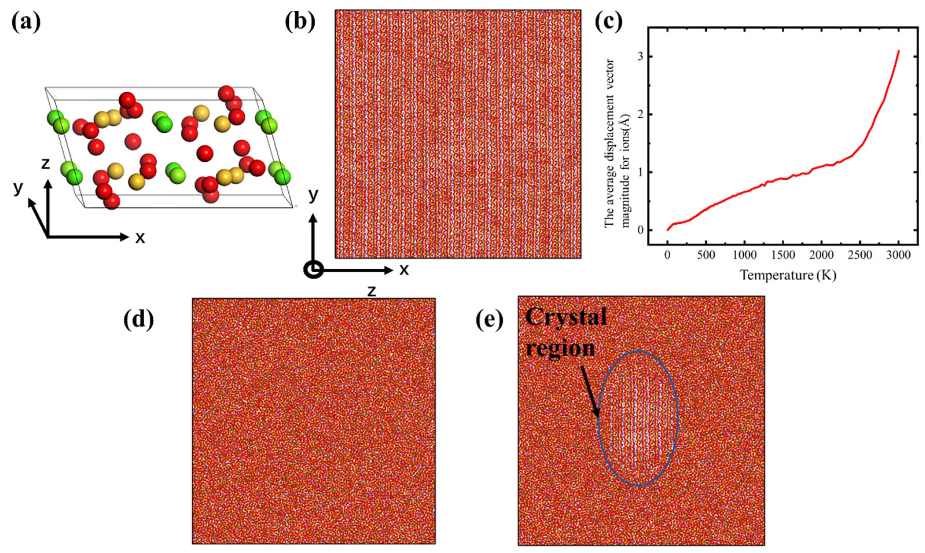
- To create the glass structure, a slab simulation box with dimensions near 20 nm × 20 nm × 2 nm was set, and then the Ca, Mg, Si and O ions were placed in the simulation box, following the diopside crystal structure, as shown in Figure 1b. The diopside cell structure belongs to the space symmetry group of C12/C1 (as shown in Figure 1a) and the lattice paraments were calculated based on the ab initio calculation, so the structure was optimized to find the ground state before MD simulation [29]. The diopside structure is also stable in the MD simulation with the CMAS94 potential. The system first minimized the energy using the conjugated gradient method, and then heated up to about 3000 K for 2 ns in NVT (canonical ensemble) [30]. A temperature of 3000 K is sufficient to melt the diopside crystal into an amorphous form. As shown in Figure 1c, as the temperature raised to about 2500 K, the average displacement vector magnitude for ions increased significantly, which means that the diopside crystal converted to amorphous melting. Finally, we cooled down the melt to 300 K over a period of 8 ns in NPT (Nose/Hoover isobaric–isothermal ensemble) with zero pressure in all three dimensions.
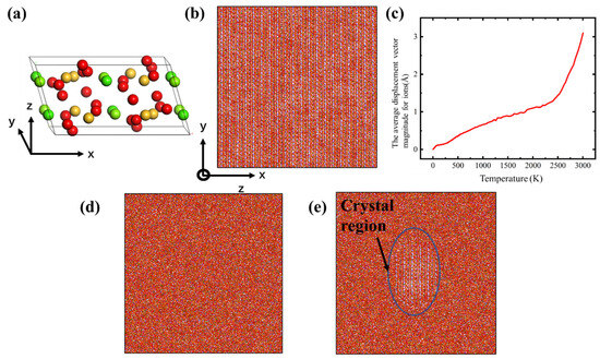 Figure 1. (a) The CaMgSi2O6 diopside cell (red for O, yellow for Si and green for Mg and Ca); (b) the CMS diopside sample; (c) plot of temperature versus average displacement vector magnitude during melting; (d) the CMS glass sample; (e) the CMS diopside GCs sample. Each ion is colored by its element type.
 - (b)
- To create the diopside GCs, we first created the CMS diopside crystal structure and then the structure was subsequently cut into ellipsoids with a radius of 4 nm. Then, we created an ellipsoid void with the same shape in the glass by deleting ions and refilled with the pre-made diopside crystal, so the diopside GCs structure was created. The total ion number in CGs samples is the same as the glass sample, to make the comparison reasonable. Finally, to relax the interface between the glass and the inserted ellipsoid crystals, the assembled samples were heated up to 1000 K and relaxed for 2 ns in the NPT ensemble with zero pressure and then cooled down to 300 K to relax for another 2 ns.
- (c)
- To create different CMAS diopside GCs samples, we adjusted the atom type in the glass phase and relaxed the system for 2 ns at 1000 K and 300 K. The total ion number for the samples in the simulation box was about 100,000. In this study, we investigated the effect of Mg, Ca and Al ion ratios, so the O and Si ion ratios would not change.
The influence of the glass phase composition in diopside GCs was studied by MD simulation. The MD simulations were performed using the LAMMPS code and the timestep was 1 fs [31]. Periodic boundary conditions were applied in all directions for all samples. The NPT ensemble was used to control the temperature and pressure. After the relaxation of each sample, uniaxial tension in the x direction was applied on all samples with a constant strain rate of 1 × 10⁸ s−1; the strain rate was much higher than that used in actual experimental tests, but was characteristic of this type of simulation method. OVITO was used to visualize the configuration of atoms in the microstructure [32].
3. Results and Discussion
3.1. Effect of the Nanocrystal
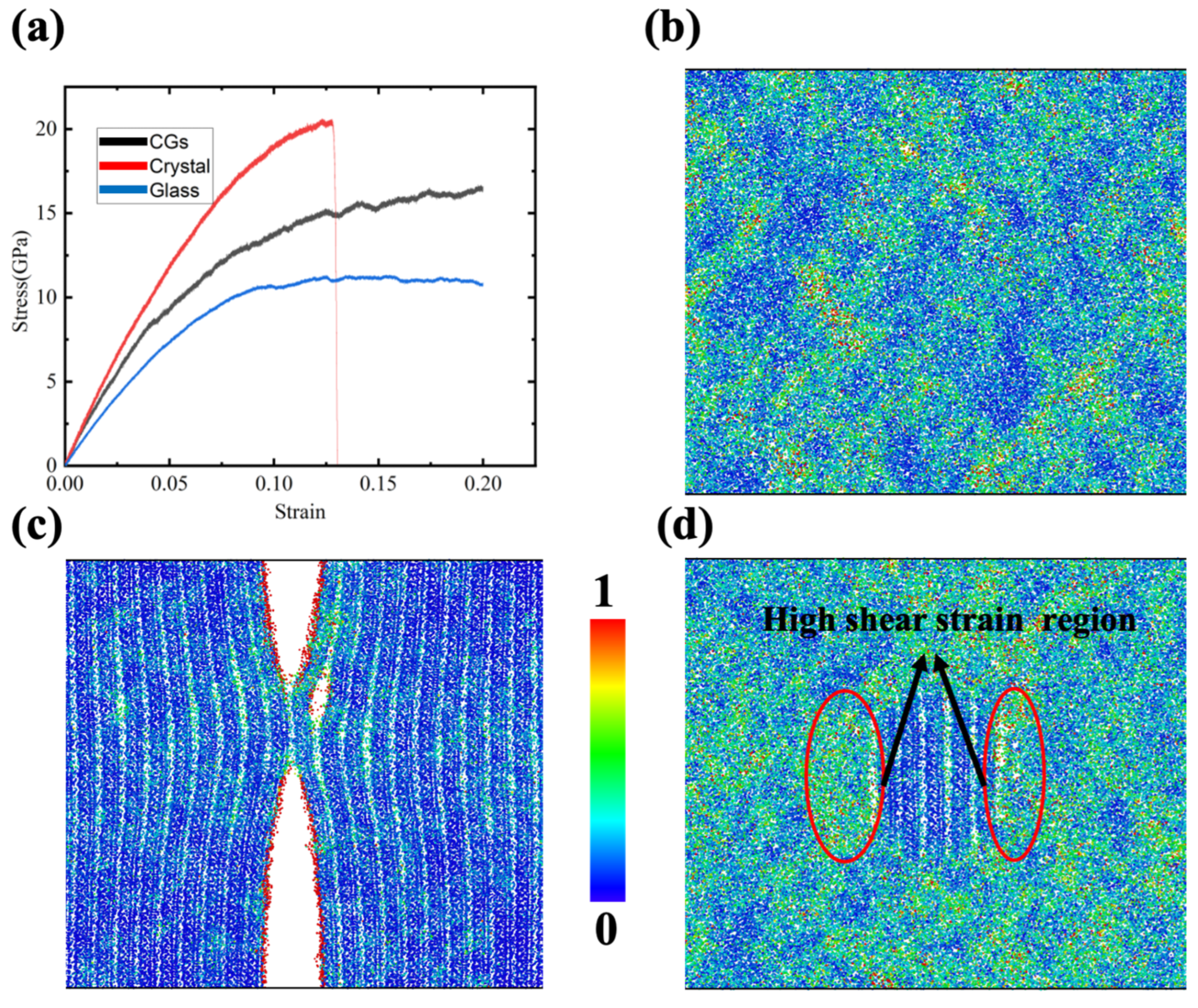
To identify mechanical property differences between GCs’ influence and their counterpart pure glass or pure crystal materials, uniaxial tension was applied on these three samples (as shown in Figure 2). Figure 2a shows the stress–strain curves for the three samples. The results are consistent with common sense, in which the ceramic crystal materials are significantly stronger than their glass material counterparts and the strength of the corresponding GCs lies in the middle. In addition, it is obvious that the stress for diopside crystalline samples drops sharply to zero at about 0.13 strain, while the other two samples still show a high and even a strain-hardening flow stress. The corresponding atomistic structure for the diopside crystalline sample is shown in Figure 2c. It is clear that the fracture takes place in the crystal. No fracture or small void exists based on Figure 2b,d. These results reveal that with the nanocrystal embedded in the glass, the strength is enhanced while ductility remains. They also echo the previous experimental results [33], which verify the reliability of the MD simulation.
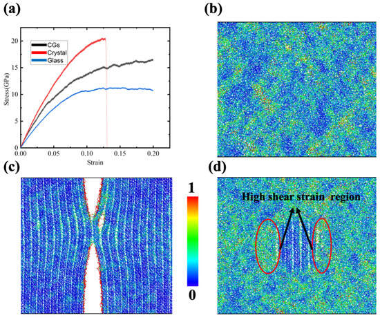
Figure 2.
(a) Stress–strain curves for CMS glass, CMS diopside and CMS diopside GC samples under tensile stress; (b) contour plots of shear strain for glass sample at 0.18 strain; (c) contour plots of shear strain for diopside sample at 0.13 strain; (d) contour plots of shear strain for CMS diopside GCs sample at 0.18 strain. Each ion is colored according to its shear strain.
Taking advantage of the atomistic simulation, the Vomis shear strain for each ion was calculated and colored based on its value, as shown in Figure 2b,c, where a red color indicates significant shear deformation. For the pure crystalline diopside sample, the high shear strain ions were concentrated at the fracture surface. For the glass sample, some areas are blue and some areas are yellow with red, indicating that the shear strain distribution is not homogeneous. It is worthwhile to mention that there is no significant high shear strain local region, which indicates that the sample is not at risk of fracture for the time being. For the diopside GCs sample, we can see that the shear strain distribution has a certain pattern, in which the ions surrounding the diopside nanocrystal are all subjected to a relatively high shear strain, while the ions in the nanocrystal are in a low shear-strain state. These findings reveal that nearly all the deformation takes place in the glass region and tends to concentrate in the region around the nanocrystal.
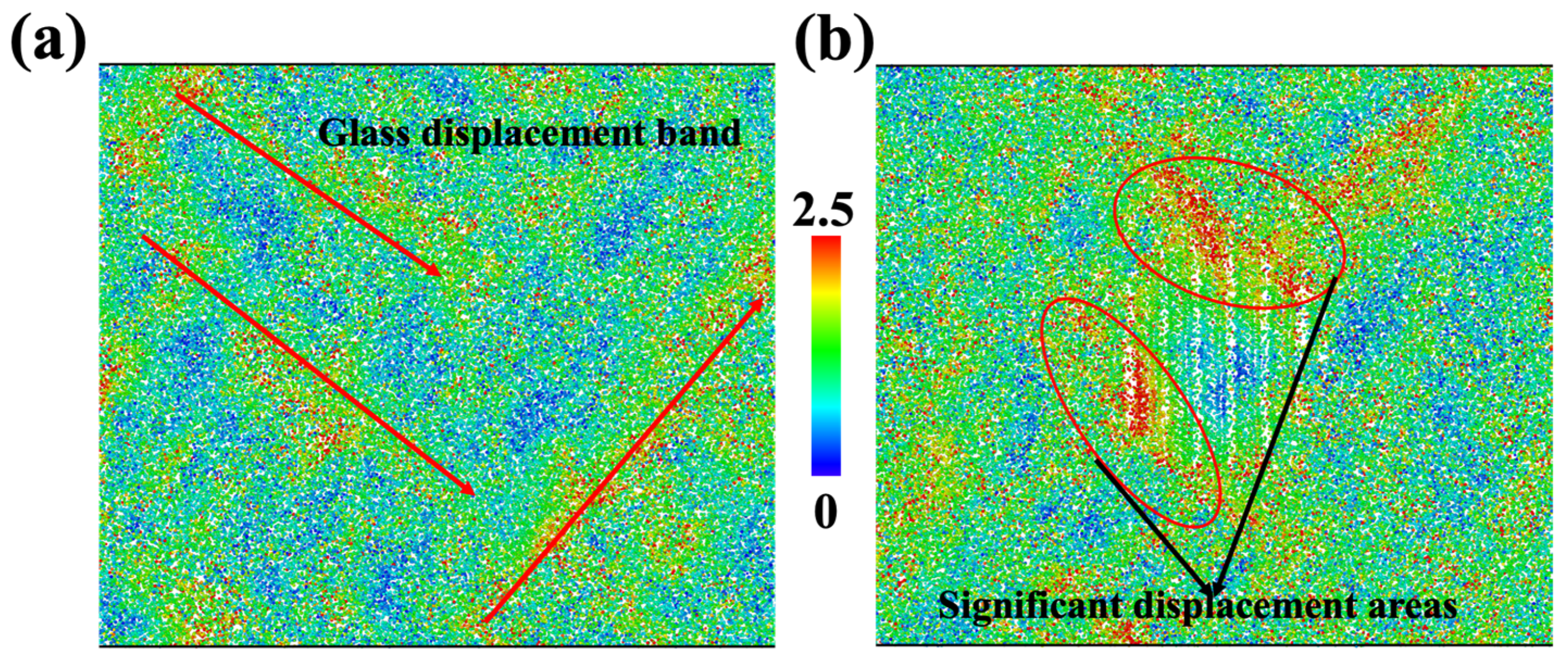
To clearly inspect the deformation pattern, we calculated the displacement vector magnitude for each ion. The homogenous cell deformations were not included in the calculation, so displacements were contributed by inelastic deformation and affected the mechanical properties of materials. As shown in Figure 3, the ions for the glass sample and diopside GCs sample are colored based on their displacement vector magnitude. On the one hand, we can see that the displacement in the glass sample followed certain bands, as shown in Figure 3a, so future fracture may take place in this region. On the other hand, the region near the top and left side of the nanocrystal has severe displacement, whose magnitude is larger than that of the glass sample. As a result, we can expect that future fracture may occur at the interface and earlier than that in pure glass sample.
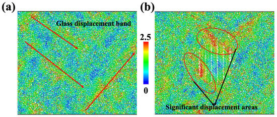
Figure 3.
Deformation map for glass sample (a) and CMS diopside GCs sample (b) at 0.18 strain. Each ion is colored according to its displacement vector magnitude; red regions represent high displacement and blue regions represent low displacement. The homogenous cell deformations are not included in the calculation, which means that the elastic displacement is not included.
3.2. Effect of the Ca/Mg Ratio in Glass Composition
To investigate how glass composition in GCs influences their mechanical properties, the ion ratios in the glass region were modified. The original atomic ratio of Ca:Mg:Si:O for the CMS diopside crystal (CaMgSi2O6) is 1:1:2:6. Oxygen ions in the system are used for the charged balance, and the coordinate number for the Si ion is significantly different for Mg and Ca ions. Therefore, for convenience, we focused on changing the Ca/Mg ion ratio. Since the Ca and Mg ions have the same charge, the creation of different GC samples was implemented by replacing certain Mg ions with Ca ions, and vice versa. As larger deviation from the standard composition may cause the failure of nucleation of diopside crystals in real experiments, the maximum replacement percentage in this study was 20%. After relaxation, all samples suffered uniaxial tension, as in the previous simulation.
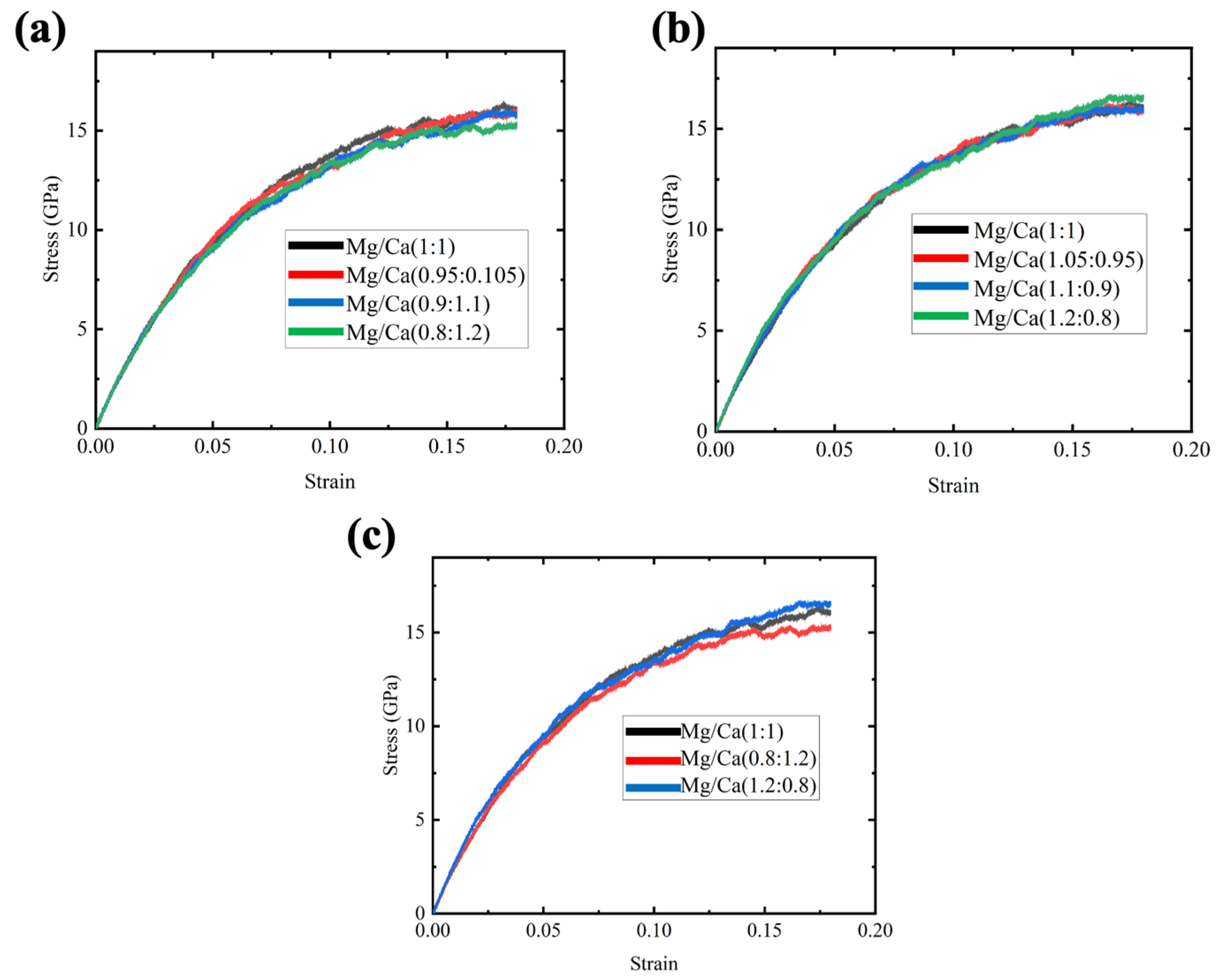
Three samples were created for each composition to avoid contingency, and the stress–strain curves were taken and averaged. Firstly, we replaced 5%, 10% and 20% Mg ions with Ca ions, and the stress–strain curves for the three compositions and the original samples are shown in Figure 4a. It was found that the composition variation has no significant effect on the strength of the GCs samples, but it was still detected that increasing the Ca ions could decrease the flow stress, especially for the case of maximum percentage of Ca ion replacement. Then, 5%, 10% and 20% Ca ions were replaced with Mg ions, and the stress–strain curves of these Mg-rich samples are shown in Figure 4b. With the increase in Mg content, the strength increases slightly. Previous experimental results also showed that the addition of MgO would increase the Young’s modulus of glass [34]. The strengthening effect was too small to be observed for the 5% and 10% Mg-replaced samples. To show the trend of strength benefits from the high Mg content ratio clearly, the stress–strain curves comparing the original sample and another two 20% replacement samples are presented in Figure 4c. It has been noticed that replacing 20% Mg with Ca would reduce the flow stress decrease by about 10%. Interestingly, compared to the original sample, the Mg-rich samples showed high flow stress until about 0.14 strain and the enhancement was very small. These results reveal that the strength of the glass would be affected by the Ca/Mg ratio and a low Ca ratio is preferred.
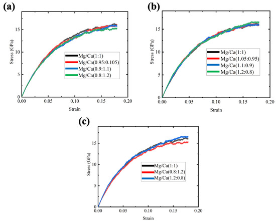
Figure 4.
Stress–strain curves for CMS diopside GCs samples under tensile stress. (a) Four samples with Mg/Ca ion ratios varying from 1:1 to 0.8:1.2; (b) four samples with Mg/Ca ion ratios varying from 1:1 to 1.2:0.8; (c) three samples with Mg/Ca ion ratios varying from 0.8:1.2 to 1.2:0.8.
One obvious difference between Ca2+ and Mg2+ is their radii. Since Mg2+ has a relatively smaller radius, the coordination number for Mg2+ (4.5–5) is smaller than that of Ca2+ (6) [35]. As the MgO and CaO cannot form glass, the low coordination number means that Mg2+ is a better glass network modifier than Ca2+, which may improve the mechanical properties of glass. A previous NMR study by Eckert et al. [36] showed that the high crack-resistant 60SiO2-10Al2O3-10B2O3-10MgO-10Na2O glasses benefit from the network formation role of Mg2+. A recent MD simulation performed by Deng et al. [37] also revealed the MgO plays a dual role as a glass network modifier/charge compensator and a network former. In addition, the machine learning model developed by the Yakobson groups can predict the correlations between atomic radius and the hardness [38]. The tendency for higher Mg2+ ratio lead towards higher hardness compared with Ca2+ may be further analyzed with reference to their model in future work.
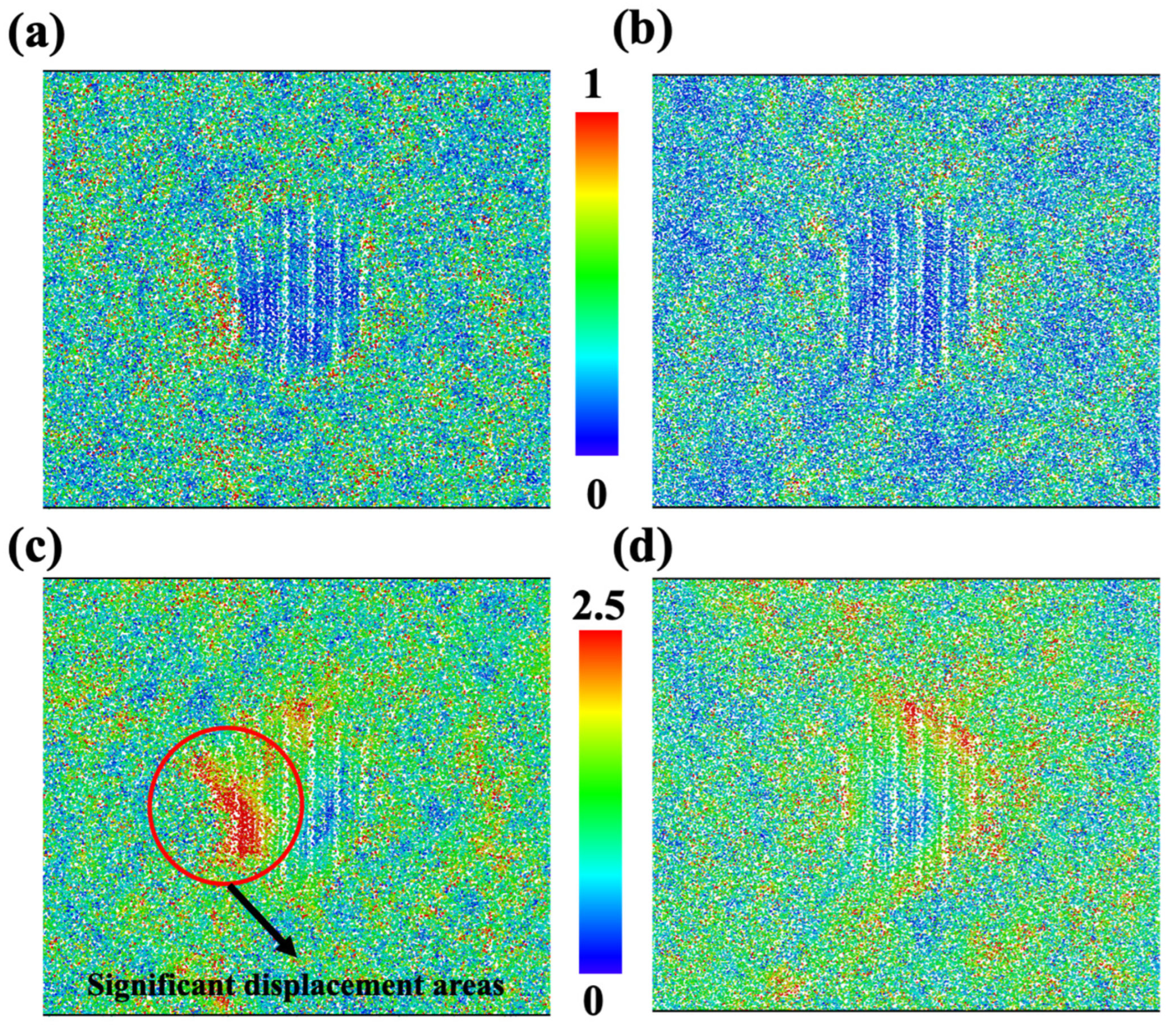
To find the underling deformation mechanism in this work, the atomic structures of Ca-rich (Figure 5a,c) and Mg-rich samples (Figure 5b,d) were evaluated. As mentioned before, ions in Figure 5a,b are colored based on shear strain, and ions in Figure 5c,d are colored by the magnitude of the displacement vector. On the one hand, the shear strain in the Mg-rich sample is clearly smaller than that in the Ca rich samples. High shear strain would imply more inelastic deformation, which could decrease the flow stress. On the other hand, we can see that the displacement of ions in the Mg-rich sample is more homogeneous, not only compared to the Ca-rich sample, but also to the original samples, as shown in Figure 3b. The significant displacements in the Ca-rich sample are still located near the nanocrystal and parallel to the loading direction. Although no fractures or voids were found in the Ca-rich sample, the aggregated displacement in the region may suggest an impending fracture. These findings indicate that the increase in Ca content will not be conducive to the strength and ductility of diopside GCs.
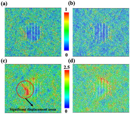
Figure 5.
Atomistic structure for CMS diopside GCs with Mg/Ca ion ratios equal to 1.2:0.8 (a,c) and 0.8:1.2 (b,d). Ions in (a,b) are colored according to their shear strain. Ions in (c,d) are colored according to their displacement vector magnitude.
3.3. Effect of the Al in Glass Composition
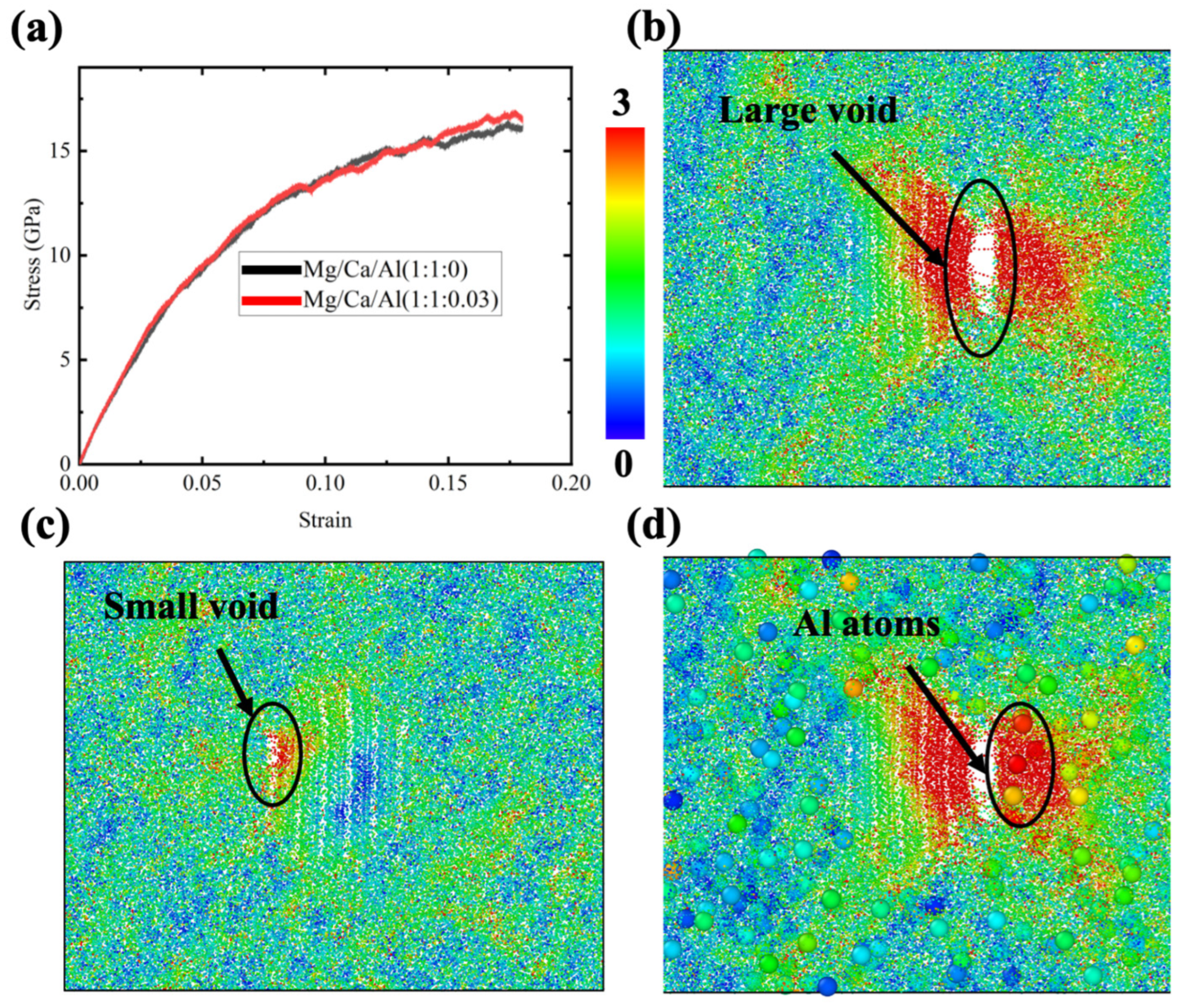
Although no Al ions exist in the diopside crystal, the glass region may contain a small amount of Al. Since the addition of Al2O3 would significantly compromise the bioactivity, as mentioned before, the CMAS diopside GCs samples in this study contained only 2% Al ions (relative to the Ca or Mg ions). Three samples were prepared by replacing 1% of Ca ions and 1% of Mg ions with Al ions. Since the charge for Al is different, the corresponding O ions were added to make the charge balance. The comparison of the average stress–strain curves between the Al-containing sample and original sample is shown in Figure 6a. Note that the sample with the Al ion demonstrates a decreasing flow stress after 0.15 strain. Previous experimental results showed that the addition of Al2O3 to glass would increase the strength [27], so the finding in this study is surprising. To find out the reason, atomistic structures for samples were examined. Notice that voids appeared at larger strains in all three samples. A larger void and a smaller one were found in Figure 6b,c, respectively. It is obvious that the void formation reduces the flow stress. The strength enhancement effect of Al2O3 was not found before 0.15 strain in this simulation, which may be due to the small addition of Al ions. Since the total number of Al ions in these samples is very small, we can directly observe their role in deformation by enlarging their representation in the atomistic structure using the visualization tool OVITO. Figure 6d demonstrates the enlarged Al ions in Figure 6b. We can see there are several Al ions coincidently close to the void in the glass region. Considering the fact that Al tetrahedra are not easily formed by linking the O ions, it seems to be reasonable that the Al ions aggregating near the crystal–glass interface would tend to promote void or fracture formation. The result shows the fact that the Al ions in CMAS diopside GCs samples are harmful to the materials’ ductility.
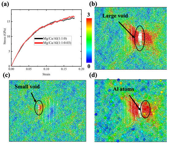
Figure 6.
(a) Stress–strain curves for CMAS diopside GCs samples under tensile stress; (b,c) atomistic structures for two CMAS diopside GCs samples at 0.18 strain; each ion is colored according to its displacement vector magnitude; (d) is the same as (b) except for the magnification of Al ions.
4. Conclusions
In summary, inspired by the superior mechanical properties and the promising biomedical potential applications of diopside GCs, we applied the first fundamental atomistic simulation to study the diopside GCs and the effect of composition on their mechanical properties. We observed that the strength of the GCs lay between their glass and ceramic counterparts, while the ductility of GCs was still considerable. The shear strain and displacement of ions revealed that the presence of nanocrystal in glass changed the original deformation pattern and made the deformation concentrated, surrounding the nanocrystal. In addition, although small, the composition of the CMAS glass would indeed influence GCs’ mechanical properties. We demonstrated that the increase in Ca ion ratio and the decrease in Mg ion ratio in glass would decrease the strength of the GCs. The shear strain map showed that the increase in Ca ion ratio can promote inelastic deformation. The displacement map reveals that the larger Mg ion ratio would make the deformation more homogeneous, and the increase in the Ca ion ratio may cause the ductility to deteriorate. Finally, our study suggests that the Al content should be as small as possible, since its strengthening effect is nearly negligible, while the Al ions may promote the formation of fractures or voids. This is the first time that the CMAS diopside GCs have been studied using atomistic simulation, so the model in this work is relatively simple, but the finding still sheds light on the structure deformation map, which benefits the design of better strength ductile diopside GCs. Future works will involve more complicated models and chemical composition.
Author Contributions
Writing of original manuscript, S.H.; experiment, B.L., S.H. and Y.S.; data analysis, S.H. and G.L.; resources, Y.S. and W.G.; manuscript revision, N.Q. and Y.S. All authors have read and agreed to the published version of the manuscript.
Funding
This research was supported by the Professorial and Doctoral Scientific Research Foundation of Huizhou University (2020JB026), the Indigenous Innovation’s Capability Development Program of Huizhou University (HZU202006), the Department of Education of Guangdong Province (2023KQNCX080), the Open Fund for Guangdong Provincial Key Laboratory of Electronic Functional Materials and Devices (EFMDN2021006M), the Department of Education of Guangdong Province (2020KQNCX082), the National Natural Science Foundation of China (22202078) and the Guangdong Province Key Construction Discipline Research Ability Enhancement Project (2022ZDJS053).
Institutional Review Board Statement
Not applicable.
Informed Consent Statement
Not applicable.
Data Availability Statement
The data presented in this study are available on request from the corresponding author.
Conflicts of Interest
The authors declare no conflicts of interest.
References
- Hland, W.; Beall, G. Applications of Glass-Ceramics. Glass-Ceram. Technol. 2012. [Google Scholar] [CrossRef]
- Deubener, J.; Allix, M.; Davis, M.J.; Duran, A.; H?Che, T.; Honma, T.; Komatsu, T.; Krüger, S.; Mitra, I.; Müller, R. Updated definition of glass-ceramics. J. Non-Cryst. Solids 2018, 501, 3–10. [Google Scholar] [CrossRef]
- Mastelaro, V.R.; Bayer, P.S.; Zanotto, E.D. Crystallization mechanism and kinetics of a Fe-diopside (25CaO 25MgO·50SiO2) glass–ceramic. J. Mater. Sci. 2019, 54, 9313–9320. [Google Scholar] [CrossRef]
- Zanotto, E.D. A Bright Future for Glass-Ceramic. Am. Ceram. Soc. Bull. 2010, 89, 19–27. [Google Scholar]
- Gong, W.; Luo, Z.; Liu, Y. Crystallization kinetic and dielectric properties of CaO–MgO–Al2O3–SiO2 glass/Al2O3 composites. Int. J. Mater. Res. 2022, 113, 520–528. [Google Scholar] [CrossRef]
- Ye, F.; Liu, L.; Wang, Y.; Zhou, Y.; Peng, B.; Meng, Q. Preparation and mechanical properties of carbon nanotube reinforced barium aluminosilicate glass–ceramic composites. Scr. Mater. 2006, 55, 911–914. [Google Scholar] [CrossRef]
- Ritzberger, C.; Apel, E.; Höland, W.; Peschke, A.; Rheinberger, V.M. Properties and Clinical Application of Three Types of Dental Glass-Ceramics and Ceramics for CAD-CAM Technologies. Materials 2010, 3, 3700–3713. [Google Scholar] [CrossRef]
- Huang, X.; Zheng, X.; Zhao, G.; Zhong, B.; Zhang, X.; Wen, G. Microstructure and mechanical properties of zirconia-toughened lithium disilicate glass–ceramic composites. Mater. Chem. Phys. 2014, 143, 845–852. [Google Scholar] [CrossRef]
- Song, G.W.Z. Effects of P2O5 and sintering temperature on microstructure and mechanical properties of lithium disilicate glass-ceramics. Acta Mater. 2007, 55, 3583–3591. [Google Scholar]
- Hooshmand, T.; Parvizi, S.; Keshvad, A. Effect of Surface Acid Etching on the Biaxial Flexural Strength of Two Hot-Pressed Glass Ceramics. J. Prosthodont. 2008, 17, 415–419. [Google Scholar] [CrossRef]
- Li, D.; Guo, J.W.; Wang, X.S.; Zhang, S.F.; He, L. Effects of crystal size on the mechanical properties of a lithium disilicate glass-ceramic—ScienceDirect. Mater. Sci. Eng. A 2016, 669, 332–339. [Google Scholar] [CrossRef]
- Rawlings, R.D.; Wu, J.P.; Boccaccini, A.R. Glass-ceramics: Their production from wastes—A Review. J. Mater. Sci. 2006, 41, 733–761. [Google Scholar] [CrossRef]
- Barbieri, L.; Lancellotti, I.; Manfredini, T.; Pellacani, G.C.; Rincón, J.M.; Romero, M. Nucleation and Crystallization of New Glasses from Fly Ash Originating from Thermal Power Plants. J. Am. Ceram. Soc. 2001, 84, 1851–1858. [Google Scholar] [CrossRef]
- Spotorno, R.; Ostrowska, M.; Delsante, S.; Dahlmann, U.; Piccardo, P. Characterization of Glass-Ceramic Sealant for Solid Oxide Fuel Cells at Operating Conditions by Electrochemical Impedance Spectroscopy. Materials 2020, 13, 4702. [Google Scholar] [CrossRef] [PubMed]
- Chen, X.; Liao, X.; Huang, Z.; You, P.; Yin, G. Synthesis and characterization of novel multiphase bioactive glass-ceramics in the CaO-MgO-SiO2 system. J. Biomed. Mater. Res. Part B Appl. Biomater. 2010, 93, 194–202. [Google Scholar] [CrossRef]
- Zhang, M.; Pu, X.; Chen, X.; Yin, G. In-vivo performance of plasma-sprayed CaO–MgO–SiO2-based bioactive glass-ceramic coating on Ti–6Al–4V alloy for bone regeneration. Heliyon 2019, 5, e02824. [Google Scholar] [CrossRef]
- Feng, K.C.; Wu, Y.J.; Wang, C.Y.; Tu, C.S.; Chen, P.Y. Enhanced mechanical and biological performances of CaO-MgO-SiO2 glass-ceramics via the modulation of glass and ceramic phases. Mater. Sci. Eng. C 2021, 124, 112060. [Google Scholar] [CrossRef]
- Smedskjaer, M.M.; Jensen, M.; Yue, Y.Z. Theoretical Calculation and Measurement of the Hardness of Diopside. J. Am. Ceram. Soc. 2010, 91, 514–518. [Google Scholar] [CrossRef]
- Saravanan, C.; Sasikumar, S. Bioactive Diopside (CaMgSi2O6) as a Drug Delivery Carrier—A Review. Curr. Drug Deliv. 2012, 9, 583–587. [Google Scholar] [CrossRef]
- Karpukhina, N.; Hill, R.G.; Law, R.V. Crystallisation in oxide glasses—A tutorial review. Chem. Soc. Rev. 2014, 43, 2174–2186. [Google Scholar] [CrossRef]
- Gong, W.; Luo, Z.; Shen, Y. Sintering behavior, microstructure and dielectric performance of Al2O3ceramic with addition of new Bi2O3B2O3SiO2ZnO glass. J. Mater. Res. 2023, 38, 2169–2178. [Google Scholar] [CrossRef]
- Sayed, M.; Mahmoud, E.M.; Bondioli, F.; Naga, S.M. Developing porous diopside/hydroxyapatite bio-composite scaffolds via a combination of freeze-drying and coating process. Ceram. Int. 2019, 45, 9025–9031. [Google Scholar] [CrossRef]
- Tulyaganov, D.U.; Dimitriadis, K.; Agathopoulos, S.; Fernandes, H.R. Glasses and glass-ceramics in the CaO–MgO–SiO2 system: Diopside containing compositions-A brief review. J. Non-Cryst. Solids 2023, 612, 122351. [Google Scholar] [CrossRef]
- Huang, S.; Zhou, C. Fracture resistance of Cu/Nb metallic nanolayered composite. J. Mater. Res. 2019, 34, 1533–1541. [Google Scholar] [CrossRef]
- Deng, B.; Luo, J.; Harris, J.T.; Smith, C.M.; McKenzie, M.E. Toughening of Li2O-2SiO2 glass-ceramics induced by intriguing deformation behavior of lithium disilicate nanocrystal. J. Am. Ceram. Soc. 2020, 103, 965–972. [Google Scholar] [CrossRef]
- Deng, B.; Luo, J.; Harris, J.T.; Smith, C.M.; Wilkinson, T.M. Toward revealing full atomic picture of nanoindentation deformation mechanisms in Li2O-2SiO2 glass-ceramics. Acta Mater. 2021, 208, 116715. [Google Scholar] [CrossRef]
- Dimitriadis, K.; Moschovas, D.; Tulyaganov, D.U.; Agathopoulos, S. Development of novel bioactive glass-ceramics in the Na2O/K2O-CaO-MgO-SiO2-P2O5-CaF2 system. J. Non-Cryst. Solids 2020, 533, 119936. [Google Scholar] [CrossRef]
- Matsui, M. Molecular dynamics study of the structures and bulk moduli of crystals in the system CaO-MgO-Al2O3-SiO2. Phys. Chem. Miner. 1996, 23, 345–353. [Google Scholar] [CrossRef]
- Walker, A.M.; Tyer, R.P.; Bruin, R.P.; Dove, M.T. The compressibility and high pressure structure of diopside from first principles simulation. Phys. Chem. Miner. 2008, 35, 359–366. [Google Scholar] [CrossRef][Green Version]
- Nosé, S. A unified formulation of the constant temperature molecular dynamics methods. J. Chem. Phys. 1984, 81, 511–519. [Google Scholar] [CrossRef]
- Plimpton, S. Fast parallel algorithms for short-range molecular dynamics. J. Comput. Phys. 1995, 117, 1–19. [Google Scholar] [CrossRef]
- Stukowski, A. Visualization and analysis of atomistic simulation data with OVITO–the Open Visualization Tool. Model. Simul. Mater. Sci. Eng. 2009, 18, 015012. [Google Scholar] [CrossRef]
- Zanotto, E.D.; Serbena, F.C.; Hench, L.L. Compositional and microstructural design of highly bioactive 3 P2O5–Na2O–CaO–SiO2 glass ceramics. Acta Biomater. 2012, 8, 321–332. [Google Scholar]
- Mahdy, E.A.; Khattari, Z.; Salem, W.M.; Ibrahim, S. Study the structural, physical, and optical properties of CaO–MgO–SiO2–CaF2 bioactive glasses with Na2O and P2O5 dopants. Mater. Chem. Phys. 2022, 286, 126231. [Google Scholar] [CrossRef]
- Cormier, L.; Cuello, G. Structural investigation of glasses along the MgSiO3–CaSiO3 join: Diffraction studies. Geochim. Et Cosmochim. Acta 2013, 122, 498–510. [Google Scholar] [CrossRef]
- Logrado, M.; Eckert, H.; Murata, T.; Nakane, S.; Yamazaki, H. Structure-property relations in crack-resistant alkaline-earth aluminoborosilicate glasses studied by solid state NMR. J. Am. Ceram. Soc. 2021, 104, 2250–2267. [Google Scholar] [CrossRef]
- Deng, B.; Shi, Y.; Zhou, Q.; Bauchy, M. Revealing the structural role of MgO in aluminosilicate glasses. Acta Mater. 2022, 222, 117417. [Google Scholar] [CrossRef]
- Tantardini, C.; Zakaryan, H.A.; Han, Z.-K.; Levchenko, S.V.; Kvashnin, A.G. Hardness Descriptor Derived from Symbolic Regression. arXiv 2023, arXiv:2304.12880. [Google Scholar]
Disclaimer/Publisher’s Note: The statements, opinions and data contained in all publications are solely those of the individual author(s) and contributor(s) and not of MDPI and/or the editor(s). MDPI and/or the editor(s) disclaim responsibility for any injury to people or property resulting from any ideas, methods, instructions or products referred to in the content. |
© 2024 by the authors. Licensee MDPI, Basel, Switzerland. This article is an open access article distributed under the terms and conditions of the Creative Commons Attribution (CC BY) license (https://creativecommons.org/licenses/by/4.0/).

