Abstract
Gear modification, which involves the removal of material from the theoretical surface to improve the contact characteristics of the gear face, is widely applied in gear vibration reduction and noise optimization design. This paper establishes a dynamic model of the straight bevel gear (SBG) transmission system to accurately and efficiently evaluate the effects of different modification strategies on the vibrational characteristics of SBGs. Initially, the time-varying meshing stiffness (TVMS) of standard SBGs was calculated, and methods such as the slicing method and deformation coordination equations were used to calculate the TVMS under tooth profile modification (TPM), Lead crown relief (LCR), and comprehensive modification (CM), which were then validated against finite element method (FEM) calculations. Subsequently, taking into account the impact of time-varying meshing point vectors and the degree of contact overlap, a finite element node dynamic model of the SBG transmission system was established. Finally, by comparing the dynamic characteristics under different modification conditions, the study further elucidates that selecting the appropriate modification method and amount according to different service scenarios is an effective means to suppress gear transmission vibration. This research provides a theoretical basis for the design of gear modification and vibration control for SBGs.
1. Introduction
The internal structure of a gear system includes numerous mechanical components, forming an elastic mechanical system where the components are coupled and connected [1]. The dynamic characteristics of vibration and noise have always been major challenges in gear system research. The dynamic excitations of a gear system are mainly divided into two parts: external and internal excitations. External excitation is similar to that of general mechanical systems, such as the primary torque of the prime mover and load resistance, while internal excitation is generated within the system during the gear meshing process. Internal excitation is a key issue in gear system dynamics, and its correct establishment ensures the rationality of dynamic response predictions for the system. SBGs are used to transmit motion and power between intersecting shafts. They offer advantages such as compact structure, ease of manufacture, easy maintenance, and low cost. As a result, they are widely used in industrial transmission equipment and automotive differentials. Because the gear teeth are straight, each pair of teeth engages suddenly along their full length, resulting in impact loads and unstable operation during high-speed transmission, which also generates considerable noise. Therefore, gear modifications are necessary to achieve vibration and noise reduction [2,3].
The precise calculation of time-varying meshing stiffness has been a research hotspot for many scholars. Tian [4] proposed a method for calculating the meshing stiffness of spur gears based on the potential energy method, but it did not account for the fillets and gear bodies of typical gears. Sainsot et al. [5] developed a meshing stiffness calculation model for gear blanks, providing a more detailed consideration of the overall stiffness during the gear meshing process. Sun et al. [6] proposed a time-varying meshing stiffness model for modified gears based on actual machining, which showed excellent agreement with finite element results. Ma et al. [7] investigated meshing stiffness in spur gears with spalling. Tang Jinyuan et al. [8] proposed a finite element method for calculating the meshing stiffness of spiral bevel gears, which has general applicability but slower computational efficiency. Chen et al. [9] fully considered the coupling effect between gear pairs and provided an analytical solution for the meshing stiffness of straight bevel gears based on the slicing method. Li et al. [10] divided spiral bevel gears and treated them as spur gears to further calculate the deformation of the gear teeth and obtain the mesh stiffness of the spiral bevel gears. In addition to time-varying meshing stiffness and backlash, many other nonlinear excitations affect the dynamic response of gear pairs. Gou et al. [11] considered multi-state meshing, load distribution rates, time-varying meshing stiffness, and backlash to establish a dynamic model of a straight bevel gear system, investigating the effects of meshing frequency and transmission error on the system’s dynamic characteristics; however, their mesh stiffness model employed a calculation model based on the gear blank stiffness of spur gears and did not consider the influence of contact stiffness.
Some researchers have shown interest in establishing more comprehensive gear system dynamics. Li et al. [12] proposed a method for calculating static transmission error based on measured tooth surfaces, which can determine the effects of assembly errors and eccentricity. Peng [13] established a dynamic model of hypoid gears and studied the influence of assembly errors, gyroscopic effects, gear eccentricity, external excitation, and dry friction on the dynamic performance of gears. Wang [14,15] proposed a multi-point coupled meshing model using multiple springs to simulate the meshing characteristics of multiple pairs of teeth in multi-tooth regions. F. Djemal et al. [16] established a system dynamics model for differential structures and studied the vibration characteristics of SBGs in differentials. Ma et al. [17] established a dynamic model for spur gear transmission systems with different modifications and sought optimal modification parameters. Habibollah Motahar et al. [18] studied the vibration characteristics of bevel gears under tooth profile modification but did not consider the time-varying spatial meshing characteristics of bevel gears. Alireza Talakesh et al. [19] studied the calculation method of mesh stiffness for SBGs, but did not consider Hertz contact stiffness under different loads. Moslem Molaie et al. [20] considered the complex internal excitations of spiral bevel gears and conducted a detailed analysis of their intricate dynamic behaviors, providing an approach for the parameter design and dynamic characteristic control of spiral bevel gear drive systems. F.S. Samani et al. [21] studied the effects of shaft stiffness and elastic deformation on vibration response by considering different support positions and types of torque (constant torque and periodic torque). Wassim Lafi et al. [22] studied the impact of time-varying uncertain parameters on the system response in a two-stage straight bevel gear system. However, the calculation of meshing stiffness was not validated, and the dynamic model established using the lumped mass method could not comprehensively consider the transmission system. S.D. Yavuz et al. [23] developed a dynamic model of a transmission system composed of spiral bevel gear pairs, shafts, and bearings to investigate the influence of coupling effects on system dynamics. S. Chowdhury et al. [24] modeled the shaft as a rotating cantilever beam to analyze the vibration characteristics of helical gear transmission systems. Hongzheng Han et al. [25] used the finite element method to calculate mesh stiffness and established a dynamic model for bevel gear-coupled planetary gear transmission systems. However, they did not address the actual spatial meshing characteristics of spiral bevel gears, using equivalent meshing points to establish the meshing pair model. Despite the substantial amount of research conducted, the aforementioned dynamic modeling does not take into account the time-varying nature of the gear meshing position and the influence of the degree of overlap. Therefore, the effects of gear modification on the dynamic characteristics of the gear system, as well as associated issues of vibration and noise, still require further investigation.
Tooth Contact Analysis (TCA) is a basic means of studying gear transmission systems, with detailed explanations provided by Litvin [26,27]. This paper addresses the contact analysis of SBGs by determining the TVMS under various modification conditions and performing a comparative analysis with the finite element method. The findings demonstrate that computational efficiency is significantly enhanced while maintaining accuracy, facilitating the resolution of practical engineering problems. By considering the meshing characteristics of SBGs, a comprehensive dynamic model of a system comprising two shafts, bearings, and gears is constructed using the finite element node method. The Newmark-beta method is employed to iteratively solve the system’s response, allowing for a comparison of the impact of meshing stiffness under different modification conditions on the gear system. This approach offers a dynamic perspective for selecting gear modification techniques and extents.
2. Time-Varying Meshing Stiffness Calculation Model
2.1. The TCA Environment
TCA is capable of reflecting the contact performance of gears, providing relevant parameters such as meshing position and overlap. Integrating contact analysis, calculating the time-varying meshing stiffness of gears, and conducting dynamic analysis allow for a more realistic representation of gear meshing performance and vibration characteristics.
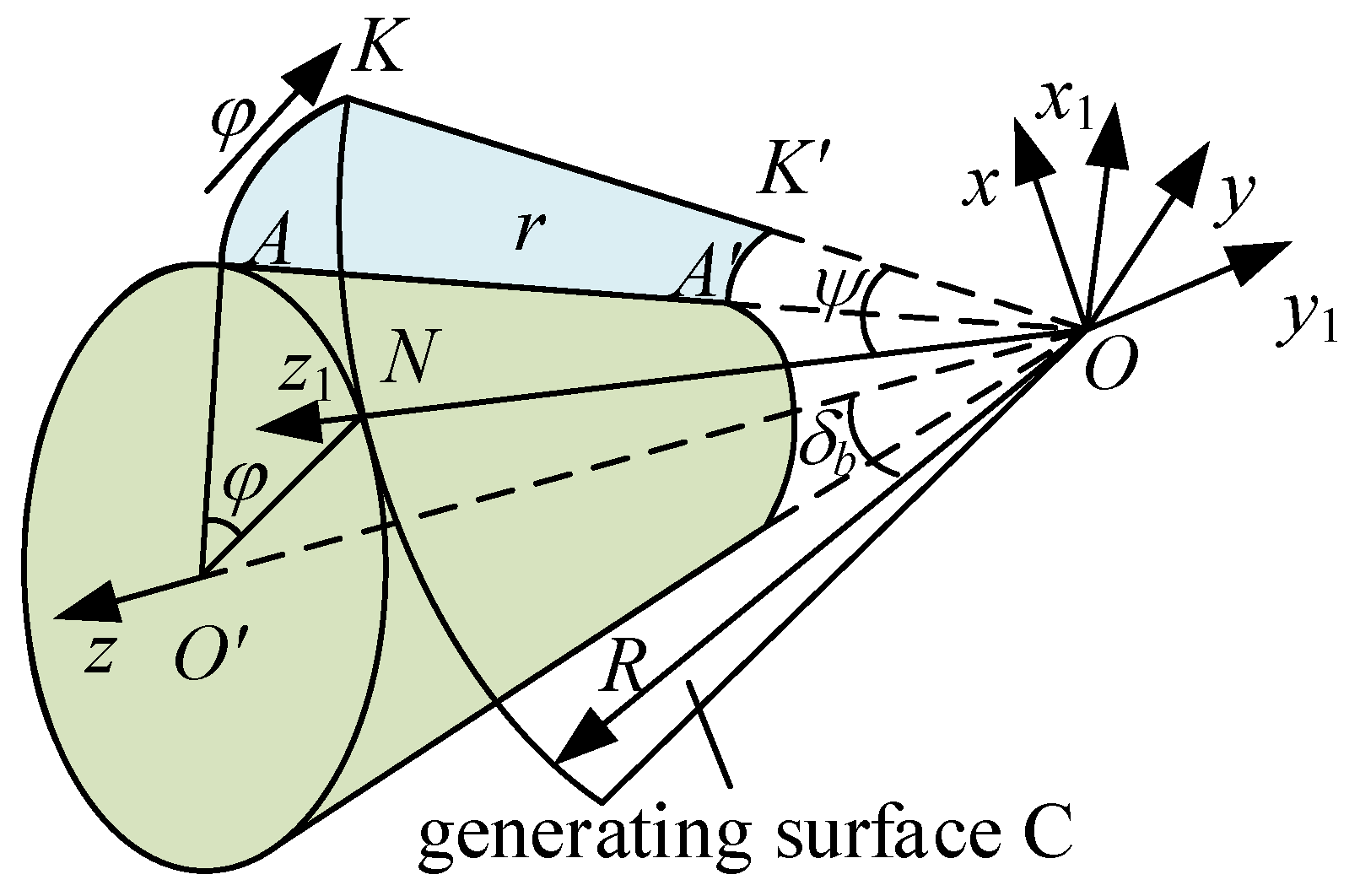
2.1.1. The Principle of Straight Bevel Gear Tooth Surface Generation
As shown in Figure 1, generating surface C of a straight bevel gear is a circular subset of a plane, with its center coinciding with the top O of the base cone and its radius equal to the base cone distance R. The generating surface C is tangent to the cone generatrix length, and the tangent line is A′A. When the generating surface C undergoes pure rolling around the base cone, the tangent line A′A sweeps to form a curved surface called an involute cone, the theoretical tooth surface of a straight bevel gear. A spherical surface is created with the cone top O as the center and the cone distance R as the radius. The intersection of the spherical surface and the involute cone results in the spherical involute. Straight bevel gears’ theoretical tooth surface can also be composed of spherical involutes with different radii centered on the cone top. For example, the small end spherical involute is a spherical involute with a radius of OA′ as the spherical radius.
Figure 1.
Principle of tooth surface formation for straight bevel gears.
Then, the A′A K′K equation is as follows [28]:
where represents the base cone angle, φ denotes the angle rolled by the occurring surface, and ψ represents the angle between OK and the instantaneous axis of rotation ON, ψ = φ sin(), Ri ∈ (R − A′A, R). According to the tooth surface equation, the normal vector of the tooth surface is obtained as:
2.1.2. Contact Point Vector and Normal Vector
To perform contact analysis for straight-bevel gears, the contact range of the straight-bevel gears is obtained as follows:
First, place the obtained straight bevel gears in their assembled position. Initially, transform the coordinates of the midpoint of the tooth width on the pitch circles of both the large and small gears to the zx plane in the positive x-direction and negative x-direction. The transformation matrix is as follows:
in the formula, i = p, g represents the pinion and the gear. represents the angle of rotation of the gear projection onto the zx plane.
Then, rotate the large gear to its assembled position. ∑ represents the shaft intersection angle, and the transformation matrix is as follows:
the point vector and the normal vector of one of the pinion can be represented as:
the point vector and the normal vector of one of the gear can be represented as:
The procedure described above is as shown in Figure 2. At this time, the driving and driven gears are very close or slightly interfering. By gradually rotating the driving gear, the two gears are made to approach or move away from each other until they meet the conditions of the meshing principle, thus obtaining the initial value of the contact point. the meshing trajectory is comprised of a series of meshing points. Starting from the initial meshing point, the rotation angle θp of the pinion can be gradually adjusted, either increased or decreased. This adjustment allows for the calculation of the rotation angle θg. They are required for the large gear when the tooth surfaces are in contact. The iterative process is used to determine the contact area following Formula (7).
Figure 2.
Schematic diagram of tooth surface rotation treatment.
The rotation angle matrices for the driving and driven gears are denoted as Mθp and Mθg, respectively.
This process allows us to accurately identify the coordinates of the contact points vector (ri = (rxi,ryi,rzi)) on the tooth surfaces of straight bevel gears, as well as their respective normal vectors (ni = (nxi,nyi,nzi)), where i = P, G represents the pinion and the gear, respectively. It also allows us to define the meshing region and the meshing line for the straight bevel gears, as shown in Figure 3, illustrating the meshing lines at the midpoint of the tooth width.
Figure 3.
Schematic diagram of contact analysis.
Analysis based on the parameters in Table 1 reveals the calculated results of TCA for straight bevel gear transmission under no-load conditions. Appendix A and the red line in Figure 3 illustrate the meshing point at the middle position of the tooth width. The results indicate that the meshing line is arc-shaped, and the angler of action obtained through TCA calculations can be utilized to determine the contact ratio.
Table 1.
Parameters of straight bevel gears.
2.2. Standard Straight Bevel Gear
Based on elasticity, the total meshing stiffness of a single gear pair can be expressed as [6]:
The bending stiffness, shear stiffness, axial compression stiffness, tooth blank base stiffness, and Hertz contact stiffness for tooth pair i = p, g are denoted as kb, ks, ka, kf, and kh, respectively. As the tooth shape of SBGs varies along the width direction, it is not possible to directly calculate the complete SBG bending stiffness, shear stiffness, axial compression stiffness, and tooth blank base stiffness. Therefore, as illustrated in Figure 4, base on reference [29], slicing is applied to SBGs. The slices are oriented perpendicular to the contact line, and the TCA outcomes are integrated into each cross-section to compute the meshing stiffness. The bending stiffness, shear stiffness, and axial compression stiffness for each slice j (j = 1, 2, …, n) are represented as , and , respectively. These values are cumulatively obtained by summing them according to the number of slices, resulting in kb, ks and ka.
Figure 4.
Slicing the straight bevel gear.
According to the potential energy method, the bending energy , shear energy , and axial compressive energy for each slice are expressed as follows:
Bending stiffness , shear stiffness , axial compressive stiffness for each slice can be obtained [30].
h and denote the distances from the meshing point to the gear teeth’s line of symmetry and to the base circle, respectively. At this meshing point, the interaction force F can be decomposed into a radial force Fa and a tangential force Fb along the direction of the meshing line. The variables for the elastic modulus and shear modulus are represented by E and G, respectively.
The Hertz contact stiffness is obtained based on the applied load [6]:
The fillet-foundation stiffness is obtained based on the geometric shape of the tooth germ [31].
T is the torque, Ip is the polar moment of inertia of the section, ρ is the distance from the point on the cross-section to the center of the circle.
Based on TCA and determining single or double-tooth contact regions through overlap assessment, the TVMS of SBGs is formulated as follows:
where l denotes the number of meshing pairs.
2.3. Lead Crown Relief
Due to the minor modification, this article considers the modification amount as a tooth shape error and calculates the meshing stiffness with its initial value given before. The LCR is illustrated in Figure 5, with the specific formula presented as follows [32]:
Figure 5.
Straight bevel gear.
LCR varies along the tooth width direction. The non-coupled slice method is used to calculate LCR meshing stiffness. The deformation is set as δj at the initial engagement. Based on the number of slices j. By comparing the engagement deformation and modification amount for each slice: if δ > Ex, the gears are considered meshing; whereas if δ < Ex, the gears are considered non-meshing. Exj represents the modification amount for the tooth pair after slicing [33]. The quantification for each slice can be expressed as follows:
The tooth stiffness, tooth bending stiffness, tooth shear stiffness, and tooth axial compression stiffness of each tooth after slicing are , and , respectively.
KP, , , Ex and Fd are the stiffness matrix of the pinion, total deformation matrix, deformation matrix of the pinion, total modification matrix, and total meshing force matrix. Fm represents the resultant force of the sliced meshing forces.
Firstly, calculate the initial value of Fd (when the gear is unmeshed, consider δ − Exj = 0):
Iterating on and Fd, set a meshing force error of Fe, and the load on the gear is F. When Fm − F > Fe:
where is the cycle coefficient, the right choice can speed up the calculation, choose [6].
Bring into the calculation of Fd again.
If the following equation is met, the iteration is completed.
After the iteration is completed, LCR meshing stiffness based on the slice method is:
2.4. Tooth Profile Modification
The TPM is shown in Figure 5. The change in meshing stiffness of the TPM only changes in the double-tooth zone and does not change in the single-tooth zone. Ekj represents the TPM amount in the double-tooth area of the main and driven gears, respectively. The tooth profile modification formula is expressed as [34]:
As depicted in Figure 5, the TPM is positioned following design requirements within the second double-tooth contact region. The change in meshing stiffness is limited to this double-tooth contact region, with no alterations occurring in the single-tooth contact region. The symbols represent the elastic deformations of tooth pairs within the double-tooth contact region under loading conditions. Ek, respectively, represents the TPM amounts within the double-tooth contact region for both the driving and driven gears.
According to the principle of deformation coordination, the relative comprehensive error between two adjacent meshing tooth pairs can be obtained as follows:
In the formula, represents the amount of modification for each meshing tooth pair at every slice position on the pinion and the gear.
The meshing stiffness of the TPM gear at this time is [35]:
Due to the TPM involving cutting at the tooth apex, what was originally a double-tooth contact region has now become a single-tooth contact region. Therefore, the meshing stiffness for the single-tooth contact region should be expressed as:
The TPM alters the gear mesh overlap. After calculating the overlap following profile modification using TCA, the time-varying meshing stiffness of gears during single and double-tooth alternation is computed according to Equation (15).
2.5. Comprehensive Modification
The TPM affects the alternating of single and double teeth, alleviating the sudden change in meshing stiffness. LCR changes the contact area, thus affecting the overall meshing stiffness. As shown by the green dashed line in Figure 5, the combination of the TPM and LCR forms a comprehensive modification (CM). Based on the above analysis, calculating the meshing stiffness for the CM involves separately computing the effects of the TPM and LCR, with the process illustrated in Figure 6.
Figure 6.
Calculation procedure of TVMS for a straight bevel gear pair with CM.
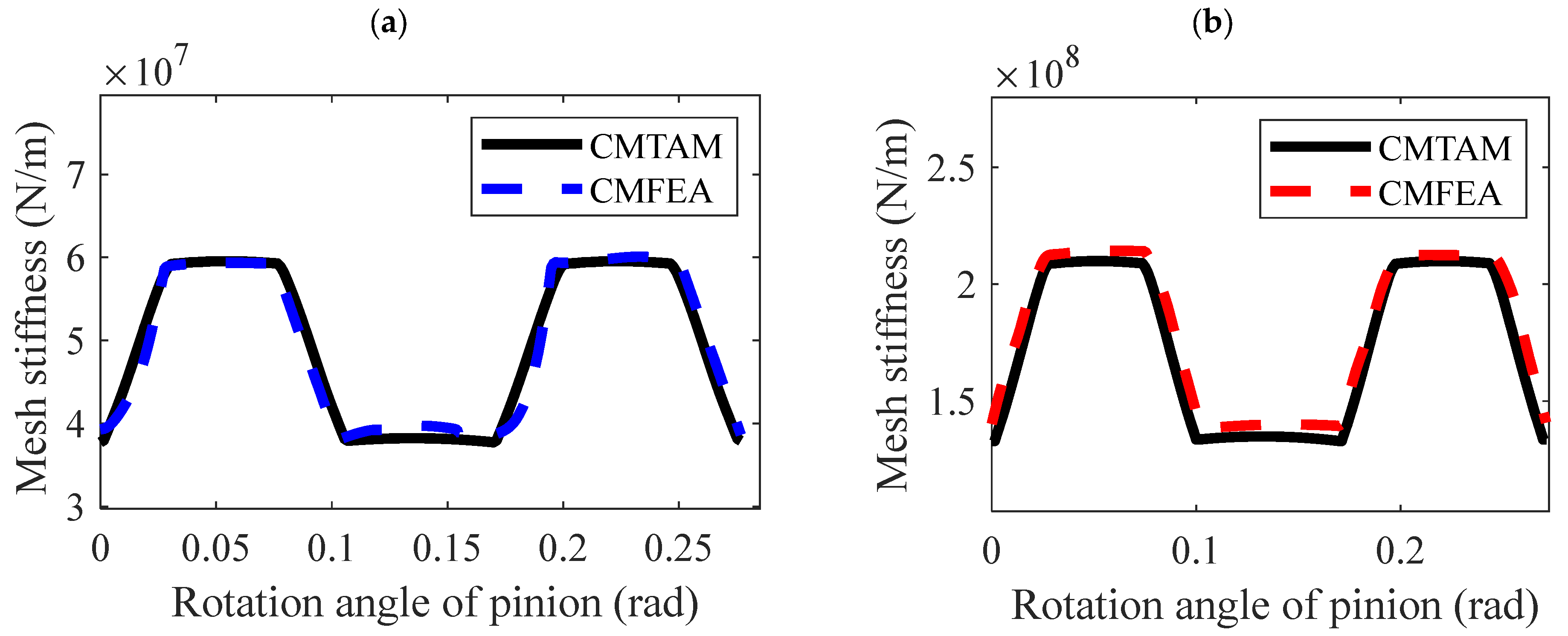
3. Finite Element Verification of TVMS
To validate the accuracy of the meshing stiffness calculations, gear models with varying parameters were established. Three-dimensional solid geometric models were imported into finite element preprocessing software to generate their finite element mesh models. Additionally, according to contact mechanics, it is known that contact pressure is highly concentrated in the vicinity of the contact area, with its intensity decreasing sharply as the distance from the contact point increases. Therefore, stress in the contact area does not depend on the geometric shape and boundary conditions far from the contact region. Considering that this study primarily focuses on stiffness variations during single-tooth contact and to avoid the influence of edge rigid body coupling constraints on the computational results, the analysis was performed by joining all gear teeth.
3.1. Finite Element Calculation Method for TVMS
This section uses a pair of straight bevel gears with different module sizes to test the accuracy of the calculation method. The three-dimensional finite element model and the modeling process are shown in Figure 7, where the drive gear is the pinion [36]. represents directional rotation radius [37], transmission error is denoted by eo, and (o = LT, NLT) represent the working load and minimal load, respectively.
Figure 7.
Finite element model of meshing gears.
To improve computational efficiency, a finer mesh is adopted for the selected mesh pair, while a coarser mesh is used for other mesh pairs. In the coupling relationship settings, the nodes on the inner circle of the gear correspond to the center position of the gear and are placed in the global coordinate system as shown in Figure 2.
The gear models with geometric parameters and modification parameters of the gear model are shown in Table 2. Using analytical and finite element methods, the time-varying meshing stiffness is calculated, respectively, followed by a comparative analysis to verify the results.
Table 2.
Parameters of straight bevel gears.
3.2. Standard Straight Bevel Gear
The time-varying meshing stiffness of standard straight bevel gears, calculated based on the relevant parameters obtained from contact analysis such as contact points, α, and overlap, is compared with the finite element simulation results, as shown in Figure 7. It is observed that the meshing stiffness of straight bevel gears exhibits significant jumps at the points of single and double-tooth alternation. However, in the finite element simulation, due to the influence of loads during gear contact, the single and double-tooth alternation does not manifest as a step-like jump as in theoretical simulations; instead, it exhibits a certain inclined angle.
As shown in Figure 8, the FEM and TAM display high consistency. Table 3 presents a comparative analysis of the errors and computational efficiency for both FEM and TAM. In Table 3, Table 4, Table 5 and Table 6, A and B represent the locations of maximum error in the double-tooth and single-tooth meshing regions, respectively.
Figure 8.
TVMS of Straight Bevel Gears. (a) gear pair 1. (b) gear pair 2.
Table 3.
Comparison of FEM and TAM.
Table 4.
Comparison of LCRFEM and LCRTAM.
Table 5.
Comparison of TPMFEM and YPMTAM.
Table 6.
Comparison of CMFEM and CMTAM.
3.3. Lead Crown Relief
Unmodified straight bevel gears are line contacts. After the LCR, the gear changes along the tooth width, turning from line contact to point contact and moving the contact area to the center of the tooth surface. The LCR changes the contact characteristics, resulting in a decrease in meshing stiffness. Hence, the size of the sudden change in stiffness in the single and double-tooth alternation region decreases, which means the fluctuations caused by the single and double-tooth alternation are diminished. Compared to the meshing stiffness of the unmodified situation, the shape of the meshing stiffness after tooth modification remains unchanged, but there’s a significant alteration in amplitude.
As shown in Figure 9, the LCRFEM and LCRTAM are highly consistent. Table 5 provides a comparison of the errors and computational efficiency between LCRFEM and LCRTAM:
Figure 9.
TVMS considering the LCR of Straight Bevel Gears. (a) gear pair 1. (b) gear pair 2.
3.4. Tooth Profile Modification
Figure 10 demonstrates that the TPM involves selectively removing material from the crest of the tooth, thereby enhancing the gear pair’s meshing action. This refinement leads to a smoother transition between engagements of single and paired teeth, which effectively smooths out the ‘stepped’ characteristics in the meshing stiffness curve. Nevertheless, applying the TPM reduces the proportion of double-tooth contact during a full meshing cycle, which, consequently, diminishes the gear’s load-carrying capacity. This reduction in contact area, due to material removal from the gear teeth, inherently weakens the gear’s load-bearing strength.
Figure 10.
TVMS considering the tooth profile modification of Straight Bevel Gears. (a) gear pair 1. (b) gear pair 2.
Therefore, the tooth profile modification length should not be chosen to be excessively large or too small. A considerable modification length can significantly reduce the gear’s load-carrying capacity if it exceeds the transition point between single and double-tooth meshing on the gear. Modifying the single-tooth contact region can significantly compromise the gear’s strength, which should be avoided in engineering. Conversely, selecting a modification length that is too small will not effectively reduce meshing impact phenomena. Therefore, reasonably choosing the gear tooth modification length is essential based on the specific circumstances.
Table 5 provides a comparison of the errors and computational efficiency between TPMFEM and TPMTAM:
3.5. Comprehensive Modification
CM combines the advantages and disadvantages of both LCR and the TPM. It not only adjusts the gear’s contact area to be centered on the tooth surface but also improves the abrupt changes occurring during the transition between single and double-tooth contact, making the transition process smoother and reducing the sudden changes in meshing stiffness as well as decreasing the amplitude of meshing stiffness. However, it reduces the degree of gear overlap. From the figures, it can be seen that the amplitude of the meshing stiffness in the single and double-tooth regions under CM is the same as that under LCR. The main changes occur in the single- and double-tooth transition areas and the gear overlap. Depending on the location of the TPM, the shape of the meshing stiffness will change, and the effects of CM will vary.
As shown in Figure 11, the CMFEM and CMTAM are highly consistent. The following provides a comparison of the errors and computational efficiency between CMFEM and CMTAM:
Figure 11.
TVMS considering the CMs of Straight Bevel Gears. (a) gear pair 1. (b) gear pair 2.
4. Dynamic Model of Straight Bevel Gears
A typical supported bevel gear-rotor system, as shown in Figure 12, consists of an elastic support shaft, gear rotor, and support bearings. The parameters of each component are listed in Table 7 and Table 8. The previous analysis determined that the contact line of the straight bevel gear is not a straight line but rather a curved one. A time-varying point-matrix meshing model for the straight bevel gear considering multi-tooth engagement was derived based on this condition. The finite element node diagram for the gear transmission system is depicted in Figure 12, where the input and output shafts are divided into 18 nodes, each with 6 degrees of freedom.
Figure 12.
Illustration of bevel gear transmission system.
Table 7.
Geometrical parameters of shafts.
Table 8.
Parameters of straight bevel gears and bearing.
4.1. Element Model of Gear Rotor
As shown in Figure 13, the gear wheel is simplified as a rigid rotor with three translational and three rotational degrees of freedom. According to the Lagrangian theorem, its equations can be written as [38]:
Figure 13.
Element model of gear rotor.
4.2. Gear Mesh Model
As shown in Figure 14, the input gear shaft and output gear shaft are coupled through a gear pair. The TVMS and time-invariant meshing damping () along the normal direction at the meshing point are connected between the gears. These are in series with geometric transmission error () [39]. As detailed in Section 2.1 via TCA, the rli are separately calculated in the local coordinate systems of each gear during the meshing cycle, along with the time-varying normal vectors nli. Subsequently, as shown in equation (30), the values are computed for the pinion and gear, respectively [23].
Figure 14.
Straight bevel gear pair.
Construct vector and the deflection of gear pair of action for the gear pair:
In the equation, represents the vibration displacement of the gear along the three directions x, y, and z, and represents the angular displacement around the x, y, and z axes.
The gear overlap in straight bevel gears typically does not exceed 3, so the dynamic displacement of the gear pair along the line of action(DTE) [2] for the gear pair can be expressed as:
where ldrl denote the load distribution ratio on the gear meshing pair, it can be expressed as follows:
The dynamic meshing force along the meshing line direction between the straight bevel gears can be expressed as [2]:
where bl is half of the total gear backlash, and the index of the backlash function is:
Based on the above analysis, the motion equations for the meshing pair of straight bevel gears in matrix form can be expressed as:
where Mm, and are the mass matrices, stiffness matrix, and damping matrix of the gear pair, respectively.
4.3. Element Model of the Shaft Element
As shown in Figure 15, for continuous rotor systems with variable cross-sections, it is common in engineering to discretize the physical prototype and then approximate the solution by rigorously handling the discrete model mathematically. In this section, we will use a discrete Timoshenko beam-axis finite element formulation for dynamic modeling of the axial elements. The entire continuous shaft is divided into N nodes and N-1 elements.
Figure 15.
Element model of the shaft element.
The elastic support shaft is divided into several shaft segments, and each shaft segment is modeled using two-noded Timoshenko beam elements. By using the Lagrangian equations, the motion equations for the undamped system can be obtained as follows [40]:
where , Me, , and represent the displacement vector, mass matrix, gyroscopic matrix, and stiffness matrix of the Timoshenko beam element, respectively [2].
4.4. Element Model of Bearing
The dynamic model for the bearing module is as follows:
In the equation, Cb represents the support damping matrix, and Kb represents the support stiffness matrix.
4.5. Overall Assembly Matrix
The generalized displacement vector q for the entire gear-rotor system can be expressed as:
Assembling all the elements, you can obtain the system’s overall damping matrix C, gyroscopic torque matrix G, and stiffness matrix K. The equation for the overall system of the straight bevel gear transmission system can be written as [2]:
The damping in various parts of the system is implemented using proportional damping:
Here, refer to the coefficient of mass matrix and stiffness matrix (, ), respectively.
5. Numerical Analysis
In this section, considering TVMS, es, and the variation in meshing position, vibration response analysis of the coupled rotor system is performed for four scenarios: unmodified, TPM, lead crown modification, and CM. The time-varying mesh stiffness is calculated as discussed in the second section, while other parameters are as Table 7, Table 8 and Table 9 shown.
Table 9.
Parameters of bearing.
The natural frequencies of straight bevel gears with the TPM and standard straight bevel gears are nearly identical. The natural frequencies of standard straight bevel gears, bevel gears with profile modification, and bevel gears with both profile and tooth direction modifications are as shown in Table 10, Table 11 and Table 12.
Table 10.
Critical speed and mode description for the geared rotor system.
Table 11.
Critical speed and mode description for the LCR geared rotor system.
Table 12.
Critical speed and mode description for the CM geared rotor system.
The dynamic transmission error (DTE) under different modification scenarios is obtained and presented in Figure 16, Figure 17 and Figure 18.
Figure 16.
DTE of TPM.
Figure 17.
DTE of LCR.
Figure 18.
DTE of CM.
From Figure 16, it can be observed that for the unmodified gear pair and the gear pair with the TPM, resonance peaks occur when the meshing frequency equals the 4th and 6th-order natural frequencies of the gear system. Due to the influence of nonlinear stiffness excitation and geometric transmission error, superharmonic resonance peaks appear when the meshing frequency is f4/2 and f6/2.
However, when the TPM is applied to the gear pair, the abrupt change in nonlinear stiffness excitation becomes smoother. Considering the modification, the superharmonic resonance peaks at f4/2 and f6/2 disappear, and the peak value of DTE significantly decreases. However, the extent of the reduction in DTE peak value varies depending on the degree of modification. Therefore, the TPM should be chosen based on the fluctuation of time-varying mesh stiffness and the vibration response.
From Figure 17, it can be observed that for the unmodified gear pair and the gear pair with LCR, the reduction in the amplitude of nonlinear stiffness after LCR affects the system’s natural frequencies. Resonance peaks occur when the meshing frequency equals the gear system’s 3rd and 6th-order natural frequencies. Superharmonic resonance peaks appear at meshing frequencies f2/2 and f6/2. The amplitude of DTE significantly increases, and the resonance peaks at f6 have higher peak values (LCM3, LCM4, LCM5) compared to the unmodified resonance peaks.
Figure 18 shows that resonance peaks occur when the meshing frequency equals the 3rd and 6th-order natural frequencies of the gear system. However, when considering a CM, the superharmonic resonance peaks at f4/2 and f6/2 disappear. The vibration response amplitude of the gear pair increases after CM, primarily due to the significant impact of LCR on the system’s vibration response. LCR alters the contact performance, leading to a substantial change in nonlinear time-varying meshing stiffness and an increase in displacement amplitude in the vibration response. On the other hand, the influence of the TPM leads to a smoother transition in the nonlinear time-varying meshing stiffness, resulting in a relatively minor displacement amplitude in the vibration response.
In this chapter, based on the calculation of the time-varying meshing stiffness of straight bevel gears in previous chapters, the vibration responses of straight bevel gear systems with profile modification, axial modification, and CM are studied. Firstly, a dynamic model of the gear-rotor system is established. Then, the effects of different modification methods and amounts on the vibration response of the straight bevel gear pair rotor system are analyzed. The analysis of gear modification optimization parameters on the vibration response of the straight bevel gear pair system concludes that selecting suitable modification parameters for different gear pairs can reduce the amplitude of system vibration responses. The analysis of gear modification optimization parameters on the vibration response of the straight bevel gear pair system concludes that selecting suitable modification parameters for different gear pairs can reduce the amplitude of system vibration responses.
6. Conclusions
This study addresses the meshing stiffness of straight bevel gears under various modification conditions and verifies the results using the finite element method. Additionally, a dynamic model of the straight bevel gear transmission system is developed using the finite element node method to analyze the effects of different modification conditions on the dynamic characteristics of straight bevel gears. The findings are as follows:
- The analytical algorithm for meshing stiffness of SBGs in this paper has been validated through comparison with the finite element method. The finite element calculation in this paper takes about 6 h (varying significantly based on computer configuration), while the analytical algorithm often requires only a few seconds, greatly improving efficiency while ensuring accuracy. Therefore, in dynamic simulation analysis, different modification schemes can be quickly designed according to vibration requirements.
- With profile modification, the abrupt changes in nonlinear stiffness excitation are smoothed, reducing dynamic transmission error within a specific range. When designing profile modifications, it is crucial to consider the varying requirements of time-varying meshing characteristics and vibration response characteristics when selecting profile modification amounts.
- Considering axial modification, the reduction in nonlinear time-varying meshing stiffness increases the dynamic transmission error amplitude, affecting the system’s natural frequencies. Consequently, resonance peaks shift. In designing axial modifications, the axial modification amount can be adjusted according to actual operating conditions to move resonance peaks away from the operating speed.
- When assessing the combined effects of profile and axial modifications, the change in vibration response is not merely additive, and their impacts on vibration response differ significantly. Therefore, when selecting modification parameters based on gear pair parameters and the vibration response induced by time-varying meshing stiffness excitation, minimizing or avoiding axial modification is advisable if resonance peaks do not require adjustment. Instead, control the profile modification amount to reduce system vibration while ensuring stability, thus achieving vibration reduction through modification.
Although this paper accounts for the coupling effects of gears, bearings, and shafts, it does not address the role of the gearbox housing and the flexibility of the gear disc. This oversight could result in neglecting the lateral vibration of the system’s web and the resonance of the housing under high-speed and heavy-load conditions. Future research will aim to refine the model further to more comprehensively consider all components of the entire transmission system.
Author Contributions
Validation, D.Z.; Formal analysis, Z.-Y.T.; Resources, J.-Y.T. and Z.S.; Writing—original draft, W.-T.L.; Funding acquisition, Z.-H.H. All authors have read and agreed to the published version of the manuscript.
Funding
This work is supported by the National Natural Science Foundation of China (NSFC) through Grant No. 52375071. The authors also gratefully acknowledge the support of the Hunan Provincial Natural Science Foundation of China through Grant No. 2023JJ20066 and No. 2023JJ40748.
Institutional Review Board Statement
Not applicable.
Informed Consent Statement
Not applicable.
Data Availability Statement
The data presented in this study are available on request from the corresponding author. The data are not publicly available due to privacy.
Conflicts of Interest
Author Ding Zhang was employed by the Aero Engine Corporation of China. The remaining authors declare that the research was conducted in the absence of any commercial or financial relationships that could be construed as a potential conflict of interest.
Abbreviations
| C | generating surface | R | base cone distance |
| O | origin of the coordinate system | A′A | tangent line |
| OA′ | radius of the spherical radius | rf | Gear tooth equation |
| n | normal vector of the tooth surface | φ | angle rolled by the occurring surface |
| base cone angle | ψ | the angle between OK and the instantaneous axis of rotation ON | |
| Mi | Transformation matrix of the gear projection to the zx plane | M∑ | Gear Assembly Variation Matrix |
| i | the pinion or the gear | the angle of rotation of the gear projection onto the zx plane | |
| Mθi | rotation angle matrices for the driving and driven gears | ri | contact points vector |
| ni | normal vectors of contact points vector | Z | Teeth number |
| m | Module | α | Pressure angle |
| B | Face width | ha | Addendum coefficient |
| c | Tip clearance coefficient | Ke | total meshing stiffness of a single gear pair |
| kb | bending stiffness | ks | shear stiffness |
| kh | Hertz contact stiffness | ka | axial compression stiffness |
| bending stiffness of slice | shear stiffness of slice | ||
| axial compression stiffness of slice | j | Number of slices | |
| bending energy of slice | shear energy of slice | ||
| axial compressive energy of slice | h | the distances from the meshing point to the gear teeth’s line of symmetry | |
| t | the distances from the meshing point to the base circle | F | interaction force |
| Fa | radial force | Fb | tangential force |
| E | elastic modulus | G | shear modulus |
| Ip | polar moment of inertia of the section | ρ | distance from the point on the cross-section to the center of the circle |
| K | time-varying meshing stiffness of straight bevel gears | l | the number of meshing pairs. |
| Ex | Modification of Lead crown relief | δ | deformation |
| KP | stiffness matrix of the pinion | total deformation matrix | |
| deformation matrix of the pinion | Ex | total modification matrix | |
| Fd | total meshing force matrix | Fm | resultant force of the sliced meshing forces |
| Fe | meshing force error | cycle coefficient | |
| Ek | Modification of tooth profile modification | Le | The distance from the modification position to the tooth tip. |
| xe | The distance from the start of the modification to the tip of the tooth. | σ | elastic deformations of tooth pairs within the double-tooth contact region under loading conditions. |
| Kt | meshing stiffness of the tooth profile modification | λ | directional rotation radius |
| L | Shaft end length | D | external diameter |
| Idn | Diameter moment of inertia | Idm | Polar moment of inertia |
| bl | Backlash | cm | Meshing damping |
| Kb | Bearing stiffness matrix | Cb | Bearing Damping Matrix |
| Construct vector | the deflection of gear pair of action | ||
| dynamic transmission error | geometric transmission error | ||
| Ldr | load distribution ratio | Mm | mass matrices of the gear pair |
| Cm | stiffness matrix of the gear pair | Km | damping matrix of the gear pair |
| the displacement vector of the Timoshenko beam element | Me | mass matrix of the Timoshenko beam element | |
| gyroscopic matrix of the Timoshenko beam element | stiffness matrix of the Timoshenko beam element | ||
| K | system’s stiffness matrix | C | system’s damping matrix |
| G | system’s gyroscopic torque matrix | K | system’s stiffness matrix |
| coefficient of mass matrix | coefficient of stiffness matrix |
Appendix A
Table A1.
Contact point vector and normal vector.
Table A1.
Contact point vector and normal vector.
| Pinion | rxp | ryp | rzp | nxp | nyp | nzp |
|---|---|---|---|---|---|---|
| 1 | −4.63 | 30.95 | 65.66 | −0.94 | −0.34 | 0.09 |
| 2 | −3.75 | 31.26 | 65.57 | −0.94 | −0.33 | 0.1 |
| 3 | −2.86 | 31.57 | 65.46 | −0.94 | −0.32 | 0.12 |
| 4 | −1.98 | 31.87 | 65.35 | −0.94 | −0.32 | 0.13 |
| 5 | −1.09 | 32.17 | 65.23 | −0.94 | −0.31 | 0.14 |
| 6 | −0.21 | 32.46 | 65.09 | −0.94 | −0.31 | 0.15 |
| 7 | 0.68 | 32.75 | 64.94 | −0.94 | −0.3 | 0.16 |
| 8 | 1.56 | 33.03 | 64.78 | −0.94 | −0.3 | 0.17 |
| 9 | 2.45 | 33.3 | 64.62 | −0.94 | −0.29 | 0.18 |
| 10 | 3.33 | 33.57 | 64.44 | −0.94 | −0.28 | 0.2 |
| gear | rxg | ryg | rzg | nxg | nyg | nzg |
| 1 | −4.63 | 65.66 | −30.95 | −0.94 | 0.09 | 0.34 |
| 2 | −3.75 | 65.57 | −31.26 | −0.94 | 0.10 | 0.33 |
| 3 | −2.86 | 65.46 | −31.57 | −0.94 | 0.12 | 0.32 |
| 4 | −1.98 | 65.35 | −31.87 | −0.94 | 0.13 | 0.32 |
| 5 | −1.09 | 65.23 | −32.17 | −0.94 | 0.14 | 0.31 |
| 6 | −0.21 | 65.09 | −32.46 | −0.94 | 0.15 | 0.31 |
| 7 | 0.68 | 64.94 | −32.75 | −0.94 | 0.16 | 0.30 |
| 8 | 1.56 | 64.78 | −33.03 | −0.94 | 0.17 | 0.30 |
| 9 | 2.45 | 64.62 | −33.30 | −0.94 | 0.18 | 0.29 |
| 10 | 3.33 | 064.44 | −33.57 | −0.94 | 0.20 | 0.28 |
References
- Li, R.W.J. Dynamics of Gear Systems; China Science Publishing: Beijing, China, 1997. [Google Scholar]
- Hu, Z.; Tang, J.; Zhong, J.; Chen, S.; Yan, H. Effects of tooth profile modification on dynamic responses of a high speed gear-rotor-bearing system. Mech. Syst. Signal Process. 2016, 76–77, 294–318. [Google Scholar] [CrossRef]
- Liu, G.; Parker, R.G. Dynamic Modeling and Analysis of Tooth Profile Modification for Multimesh Gear Vibration. J. Mech. Des. 2008, 130, 121402. [Google Scholar] [CrossRef]
- Tian, X. Dynamic Simulation for System Response of Gearbox Including Localized Gear Faults. Master’s Thesis, University of Alberta, Edmonton, AB, Canada, 2004. [Google Scholar]
- Sainsot, P.; Velex, P.; Duverger, O. Contribution of Gear Body to Tooth Deflections—A New Bidimensional Analytical Formula. J. Mech. Des. 2004, 126, 748–752. [Google Scholar] [CrossRef]
- Sun, Z.; Chen, S.; Hu, Z.; Tao, X. Improved mesh stiffness calculation model of comprehensive modification gears considering actual manufacturing. Mech. Mach. Theory 2022, 167, 104470. [Google Scholar] [CrossRef]
- Ma, H.; Li, Z.; Feng, M.; Feng, R.; Wen, B. Time-varying mesh stiffness calculation of spur gears with spalling defect. Eng. Fail. Anal. 2016, 66, 166–176. [Google Scholar] [CrossRef]
- Tang, J.-Y.; Pu, T.-P. Calculation of mesh stiffness of spiral bevel gear based on finite element method. Chin. J. Mech. Eng. 2011, 47, 7. [Google Scholar] [CrossRef]
- Chen, S.; Tan, R.; Guo, X.; Zhang, W.; Shu, R. Study on excitation and time-varying mesh characteristics of straight bevel gears considering modification and friction. Mech. Mach. Theory 2022, 176, 105028. [Google Scholar] [CrossRef]
- Li, H.; Tang, J.; Chen, S.; Ding, H.; Sun, Z.; Rong, K. Analytical calculation of mesh stiffness for spiral bevel gears with an improved global tooth deformation model. Mech. Mach. Theory 2024, 191, 105492. [Google Scholar] [CrossRef]
- Gou, X.-F.; Li, G.-Y.; Zhu, L.-Y. Dynamic characteristics of a straight bevel gear drive system considering multi-state meshing and time-varying parameters. Mech. Mach. Theory 2022, 171, 104779. [Google Scholar] [CrossRef]
- Li, H.; Chen, S.; Tang, J.; Chen, W.; Ouyang, H. A novel approach for calculating no-load static transmission error based on measured discrete tooth surfaces. Mech. Mach. Theory 2019, 138, 112–123. [Google Scholar] [CrossRef]
- Peng, T. Coupled Multi-body Dynamic and Vibration Analysis of Hypoid and Bevel Geared Rotor System. Ph.D. Thesis, University of Cincinnati, Cincinnati, OH, USA, 2010. [Google Scholar]
- Wang, H. Gear Mesh Characteristics and Dynamics of Hypoid Geared Rotor System. Ph.D. Thesis, The University of Alabama, Tuscaloosa, AL, USA, 2002. [Google Scholar]
- Wang, H.; Lim, T.C. Analysis of the Mesh Characteristics of Hypoid Gear Pair Dynamics. In Proceedings of the Asme International Design Engineering Technical Conferences & Computers & Information in Engineering Conference, Chicago, IL, USA, 2–6 September 2003. [Google Scholar]
- Djemal, F.; Lafi, W.; Tounsi, D.; Akrout, A.; Walha, L.; Haddar, M. Effects of mass imbalance and eccentricity defects on the automotive differential dynamics. J. Braz. Soc. Mech. Sci. Eng. 2021, 43, 419. [Google Scholar] [CrossRef]
- Ma, H.; Pang, X.; Feng, R.; Wen, B. Evaluation of optimum profile modification curves of profile shifted spur gears based on vibration responses. Mech. Syst. Signal Process. 2016, 70–71, 1131–1149. [Google Scholar] [CrossRef]
- Motahar, H.; Samani, F.S.; Molaie, M. Nonlinear vibration of the bevel gear with teeth profile modification. Nonlinear Dyn. 2016, 83, 1875–1884. [Google Scholar] [CrossRef]
- Talakesh, A.; Hadian Jazi, S.; Ariaei, A.; Poursina, M. A new experimental method for calculating mesh stiffness in healthy and cracked straight bevel gear system. Measurement 2024, 224, 113804. [Google Scholar] [CrossRef]
- Molaie, M.; Samani, F.S.; Zippo, A.; Iarriccio, G.; Pellicano, F. Spiral bevel gears: Bifurcation and chaos analyses of pure torsional system. Chaos Solitons Fractals 2023, 177, 114179. [Google Scholar] [CrossRef]
- Samani, F.S.; Salajegheh, M.; Molaie, M. Nonlinear vibration of the spiral bevel gear under periodic torque considering multiple elastic deformation evaluations due to different bearing supports. SN Appl. Sci. 2021, 3, 772. [Google Scholar] [CrossRef]
- Lafi, W.; Djemal, F.; Tounsi, D.; Akrout, A.; Walha, L.; Haddar, M. Non-probabilistic interval process method for analyzing two-stage straight bevel gear system with uncertain time-varying parameters. Proc. Inst. Mech. Eng. Part C J. Mech. Eng. Sci. 2020, 235, 3162–3178. [Google Scholar] [CrossRef]
- Yavuz, S.D.; Saribay, Z.B.; Cigeroglu, E. Nonlinear time-varying dynamic analysis of a spiral bevel geared system. Nonlinear Dyn. 2018, 92, 1901–1919. [Google Scholar] [CrossRef]
- Chowdhury, S.; Yedavalli, R.K. Vibration of high speed helical geared shaft systems mounted on rigid bearings. Int. J. Mech. Sci. 2018, 142–143, 176–190. [Google Scholar] [CrossRef]
- Han, H.; Zhang, S.; Yang, Y.; Ma, H.; Jiang, L. Modulation sidebands analysis of coupled bevel gear pair and planetary gear train system. Mech. Mach. Theory 2022, 176, 104979. [Google Scholar] [CrossRef]
- Litvin, F.L.; Donno, M.D.; Peng, A.; Vorontsov, A.; Handschuh, R.F. Integrated computer program for simulation of meshing and contact of gear drives. Comput. Methods Appl. Mech. Eng. 2000, 181, 71–85. [Google Scholar] [CrossRef]
- Litvin, F.L.; Fuentes, A. Gear Geometry and Applied Theory; Cambridge University Press: Cambridge, UK, 2004. [Google Scholar]
- Kolivand, M.; Ligata, H.; Steyer, G.; Benedict, D.K.; Chen, J. Actual Tooth Contact Analysis of Straight Bevel Gears. J. Mech. Des. 2015, 137, 093302. [Google Scholar] [CrossRef]
- Wan, Z.; Cao, H.; Zi, Y.; He, W.; Chen, Y. Mesh stiffness calculation using an accumulated integral potential energy method and dynamic analysis of helical gears. Mech. Mach. Theory 2015, 92, 447–463. [Google Scholar] [CrossRef]
- Wu, S.; Zuo, M.J.; Parey, A. Simulation of spur gear dynamics and estimation of fault growth. J. Sound Vib. 2008, 317, 608–624. [Google Scholar] [CrossRef]
- Sun, X. Mechanics of Materials; Higher Education Press: Beijing, China, 2009. [Google Scholar]
- Xia, C. Research on theTooth Modification Methods of the Straight Bevel Gear. Ph.D. Thesis, Huazhong University of Science and Technology, Wuhan, China, 2006. [Google Scholar]
- Wang, Q.; Xu, K.; Huai, T.; Ma, H.; Wang, K. A mesh stiffness method using slice coupling for spur gear pairs with misalignment and lead crown relief. Appl. Math. Model. 2021, 90, 845–861. [Google Scholar] [CrossRef]
- Walker, H. Gear Tooth Deflection and Profile Modification. Engineer 1990, 166. [Google Scholar]
- Ma, H.; Zeng, J.; Feng, R.; Pang, X.; Wen, B. An improved analytical method for mesh stiffness calculation of spur gears with tip relief. Mech. Mach. Theory 2016, 98, 64–80. [Google Scholar] [CrossRef]
- Tang, J.Y.; Cai, W.X.; Wang, Z.W. Meshing stiffness formula of modification gear. J. Cent. South Univ. Sci. Technol. 2017, 48, 337–342. [Google Scholar]
- Cao, W.; Pu, W.; Wang, J. Tribo-dynamic model and fatigue life analysis of spiral bevel gears. Eur. J. Mech.-A/Solids 2019, 74, 124–138. [Google Scholar] [CrossRef]
- Chen, S.; Tang, J.; Li, Y.; Hu, Z. Rotordynamics analysis of a double-helical gear transmission system. Meccanica 2016, 51, 251–268. [Google Scholar] [CrossRef]
- Smith, J.D. Gears and Their Vibration, A Basic Approach to Understanding Gear Noise; Marcel Dekker Inc.: Abington, UK, 1983. [Google Scholar]
- Nelson, H.D. A Finite Rotating Shaft Element Using Timoshenko Beam Theory. J. Mech. Des. 1980, 102, 793–803. [Google Scholar] [CrossRef]
Disclaimer/Publisher’s Note: The statements, opinions and data contained in all publications are solely those of the individual author(s) and contributor(s) and not of MDPI and/or the editor(s). MDPI and/or the editor(s) disclaim responsibility for any injury to people or property resulting from any ideas, methods, instructions or products referred to in the content. |
© 2024 by the authors. Licensee MDPI, Basel, Switzerland. This article is an open access article distributed under the terms and conditions of the Creative Commons Attribution (CC BY) license (https://creativecommons.org/licenses/by/4.0/).