Featured Application
For the controllable pitch propeller control system, existing control algorithms still have limitations regarding timeliness. A control law based on a model predictive control (MPC) algorithm is designed in this paper. The results of this paper have potential application value in embedded control of ship controllable pitch propeller.
Abstract
The controllable pitch propeller hydraulic system has high constraints and nonlinearity. Due to these inherent deficiencies, the proportional–integral–derivative (PID) control algorithm cannot meet the control accuracy requirements of nonlinear systems. A control law based on a model predictive control (MPC) algorithm is designed in this paper. The gain parameters of the predictive control are optimized. The MPC and PID control systems are compared and simulated to verify the MPC controller’s effectiveness. Subsequently, the embedded controller of a controllable pitch propeller is developed. The support package for the embedded circuit board target containing an underlying driver for each interface is written by introducing the C-MEX S-Function and TLC programming language. A semi-physical simulation experiment is performed. The results show that the established controllable pitch propeller with an embedded controller displays reliable running performance, good anti-interference, and the capacity to fulfill the control function of the pitch propeller under various working conditions.
1. Introduction
With the advances in the shipping industry, improved ship maneuverability and propulsion efficiency are required. The controllable pitch propeller is widely applied in ship thrust systems due to its good properties. The control research associated with this propeller is fundamental for enhancing the navigational safety and economic performance of ships. Extensive research has been conducted on the controller algorithm. Traditional methods, such as the proportional–integral–derivative (PID) control and fuzzy control, have been widely applied to control controllable pitch propellers [1,2]. By optimizing the control parameters and structures, researchers have upgraded the stability and response speed of control systems. For instance, the PID accurately controls the propeller speed and pitch angle by adjusting the proportional, integral, and derivative coefficients. Thanks to artificial intelligence technology advancements, intelligent control algorithms (i.e., neural networks and genetic algorithms) have been introduced into controllable pitch propellers. Scholarly efforts have been made to address the uncertainty when evaluating the reliability and availability of controllable pitch propeller hydraulic systems. For instance, Bai [3] applied D–S evidence theory and dynamic Bayesian networks to establish a new method for assessing their reliability and availability. Fang [4] predicted the system’s reliability using the failure rate prediction method and obtained each unit’s failure rate and reliability curve. Zhang [5] designed an adjustable pitch propeller control hydraulic system comprising an electro-hydraulic directional control valve and a proportional directional control valve, and the corresponding control strategies were proposed. Rosenkranz [6] employed the fuzzy method to control a controllable pitch propeller. However, the accuracy of this method is difficult to guarantee. Ji [7] reported that the gain loop could be treated as a nonlinear function within a specific error range; moreover, pertinent research on the ship pitch control propeller with nonlinear PID was conducted, further improving the accuracy and efficiency. Chen [8] constructed a joint controller with load protection for adjustable pitch propellers to achieve maximum thrust effectiveness. Wang [9] conducted simulation research on the ship’s controllable pitch propeller control system based on the PID. For the controllable pitch propeller control system, existing control algorithms still have limitations regarding timeliness. At the same time, the traditional design process for marine control systems faces practical issues such as long development cycles, complex procedures, and low development efficiency, which have made it increasingly difficult to meet development demands. In fields like automotive electronics and aerospace, the model-based design (MBD) method has been proven to be an effective controller design approach. Transplanting this method into the design and development of controllable pitch propeller control system undoubtedly represents an effective approach. The model predictive control (MPC) algorithm allows efficient constraint control and easy solutions to the optimal control problems arising from its limitations [10,11]. This algorithm is iterative and online in optimizing the control. It has the characteristics [12,13,14] of a control structure based on model prediction, rolling optimization, and feed-forward feedback, enabling the fast and accurate responses of the controller. Based on the above analysis, the MPC can design the controller within the controllable pitch propeller control system.
2. Modeling and Simulation
2.1. Structure
The structure of the controllable pitch propeller is schematically shown in Figure 1. The adjustment function of the blade pitch angle is available by pushing the hub with the oil pipe inside the propeller shaft to rotate the blades. A hydraulic system serves as the primary power source for a controllable pitch propeller. As illustrated in Figure 2, the oil tank supplies hydraulic oil to the system. Subsequently, the oil pressurized by the pump enters the oil circuit and flows into a three-position four-way valve in the valve block following filter filtration. The valve spool is controlled by the controllable pitch propeller controller, which alters the pressure of the hydraulic oil on both sides of the piston in the hub cylinder, enabling forward or reverse motion.
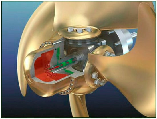
Figure 1.
Structure of the controllable pitch propeller.
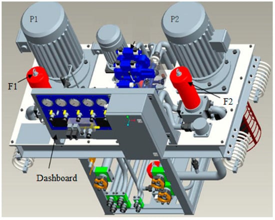
Figure 2.
Integrated hydraulic unit.
Figure 3 shows the working principle when adjusting the distance in the forward direction. The high-pressure hydraulic oil flows into the rear hydraulic cylinder chamber of the controllable pitch propeller hub through the oil distributor, and the piston is pushed forward to the bow. The oil returns on the other side of the piston. The blade pitch ratio of the controllable pitch propeller advances toward a positive value. At a positive value, the controllable pitch propeller produces a favorable thrust to the hull.
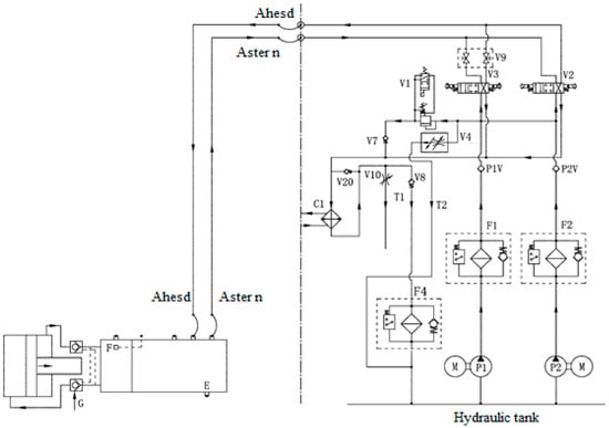
Figure 3.
Hydraulic system in the forward direction.
2.2. Thrust Calculation
The effective thrust of the controllable pitch propeller and the experimental thrust of the water flow can be calculated according to the following equations:
where stands for the thrust coefficient, indicates the seawater density (), denotes the diesel engine speed (), marks the pitch paddle diameter (), and represents the thrust derating factor.
Aiming to facilitate the calculation, the square coefficient value of the hull is typically adopted in engineering to approximate the thrust reduction factor of a single-propeller ship , and their relationship is presented in Table 1.

Table 1.
The relationship between and .
The thrust coefficient is related to the process ratio of the pitched paddle and the pitch angle. The can be expressed as follows:
The propeller feed speed can be written as:
where denotes the ship speed (), and represents the companion flow coefficient.
Typically, the effect of the hull’s squareness coefficient value is considered, and other factors are ignored. According to the squareness coefficient value , Table 2 is checked to obtain the approximate value of .
Table 2.
The relationship between and .
The pitch drag torque is affected by the torque coefficient , pitch diameter , water density , and diesel engine speed , and it can be expressed as follows:
The torque coefficient is influenced by the pitch paddle process ratio and the pitch angle . It can be calculated as follows:
Due to the calculation complexity, the flow characteristic curve of the four-blade pitch paddle torque coefficient is introduced to solve the torque coefficient and plotted in Figure 4.
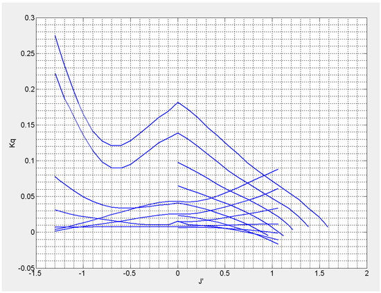
Figure 4.
Flow characteristic curves of the four-blade pitch paddle torque coefficient.
During the transmission of the controllable pitch propeller, the friction between the drive shaft and the bearings will generate the friction loss torque . This torque is related to the rotational speed of the controllable pitch propeller. Due to the comparison with the diesel output torque and the pitching paddle resistance torque , the friction loss torque is small. To simplify the calculations, the friction loss torque can be considered constant, with a magnitude of . represents the output torque of the diesel engine under the rated operating conditions.
2.3. Simulation Model
The mechanistic modeling of the controllable pitch propeller system is cumbersome and lacks intuitive clarity, and many parameters in the resulting transfer function are challenging to measure. In addition, the Simulink/SimHydraulics toolbox contains considerable hydraulic modules and commercial component-based modules that are commonly used, allowing for the realization of the physical modeling of hydraulic and hydro-mechanical systems. Herein, the Simulink/SimHydraulics toolbox is adopted for the physical modeling to establish an accurate and user-friendly mathematical model of the controllable pitch propeller system. The parameters of the hydraulic cylinder and the load settings are summarized in Table 3.
Table 3.
Hydraulic cylinder and load parameters.
The simulation model of the hydraulic system is presented in Figure 5. When the external control signal is input to the three-position four-way valve using the digital-to-analog converter module, the direction of the hydraulic fluid between the pipelines is changed, pushing the hydraulic cylinder. The mass block, spring, and damper simulate the external force on the pitch paddle blade in seawater and are connected to the hydraulic cylinder, achieving a better replication of the operating environment at sea and a more realistic simulation.
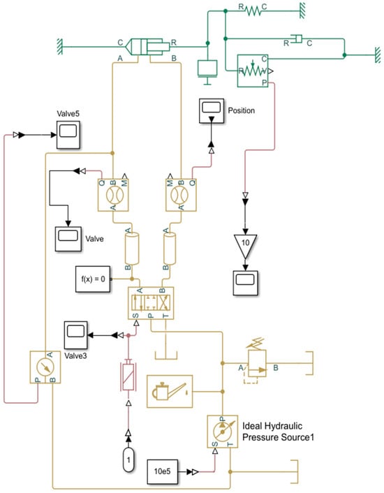
Figure 5.
Hydraulic system simulation model of the controllable pitch propeller.
Considering that obtaining the state information of the controllable pitch propeller system is challenging, the identification target is set as the transfer function of the input and output signals. Then, this function is transformed into the state space during the system identification. The input and output signals are imported using MATLAB’s system identification toolbox. The zeros and poles of the transfer function are set to be two and three, respectively.
After the identification, the final transfer function obtained aligns well with the model input and output, representing 93% conformity (Figure 6). It can be found that the conclusion is consistent with the engineering accuracy and systematically identifies the physical model of the controllable pitch propeller. The transfer function can be expressed as:
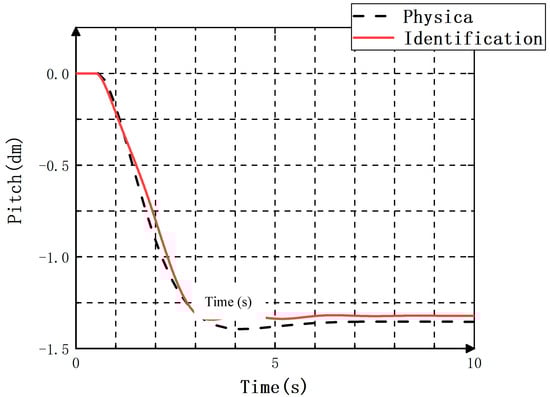
Figure 6.
System identification results.
3. The MPC Controller Design for the Controllable Pitch Propeller
3.1. Mathematical Modeling
In designing an MPC-derived controller, a mathematical model allowing for the prediction of the controlled system’s state is necessary. This model is typically described in a state-space pattern in modern control. At the moment , the state of the controlled system , the control input , and the output can be obtained. Correspondingly, the controlled model at can be written as:
According to Equation (9), is taken as the prediction time domain, the measured output of the system can be considered as the starting point of the output, and can be regarded as the beginning of the prediction state. The output of the prediction time domain can be estimated at any moment from to according to the moment . The output of the can be expressed as follows:
Subsequently, the system’s output in the prediction time domain is recorded as:
Similarly, the control input within the prediction time domain is defined as:
Each component of the control input vector is independent and needs to be solved as an optimization problem.
The controller’s goal is to minimize the output for the desired one. The reference input in the control time domain includes:
To maximize the consistency between the predicted and the expected outputs, the difference between the two output vector components should be accumulated when establishing the optimization objective function. The optimization objective function can be defined as:
For the control inputs and system outputs, constraints are generally imposed for engineering applications. The limits can be expressed as below:
Solving the optimal control inputs can be divided into two parts. First, the controller inputs to the system can minimize the output, considering the reference inputs. Second, by solving the control inputs , the control inputs and the system outputs can meet the control constraints and the output constraints .
Ultimately, an optimal solution addressing the above problem at can be obtained:
Based on the mechanical modeling and system identification of the pitch paddle hydraulic system in Section 2, Equation (9) can be rewritten in incremental form, and the hydraulic system can be represented as a state space:
where , , , corresponds to the state variable, denotes the control input variable, stands for the controlled output variable, and signifies the measurable external disturbance variable.
When the MPC controller works, the speed of solving the optimization problem will affect the controller’s timeliness. For a faster computing speed on the part of the algorithm, the number of independent variables for the optimization problem is typically reduced. The control time domain is smaller than the prediction time domain , and the control quantity is assumed to remain unchanged outside the control time domain , i.e., . Since the upcoming disturbance quantity at the current moment is unknown, the measurable disturbance is assumed to be constant after , i.e., . At , the system state is , and is considered to be the starting value for predicting the controlled system state. According to Equation (17), the state from to can be predicted:
From Equations (17) and (18), the measured output at is selected as the starting point for the system’s controlled output prediction, which can be achieved from to as follows:
The prediction output vector and input vector are defined as follows:
Equation (19) is converted to a matrix equation, and the system prediction output can be calculated by the following equation:
3.2. Optimized Design
The optimization problem design is based on two main considerations. On the one hand, the controlled output is required to be consistent with the reference input. On the other hand, imposing constraints is necessary. For the first aspect, the objective function is chosen as the form:
where is the component of the reference input, and is the weighting factor for the difference between the controlled output and the reference input. During controller design, the performance of the controllable pitch propeller is influenced by the variation between the controlled output and the reference input. When the error requirement is high, the weighting factor can be increased. Depending on the needs of a controllable pitch propeller, the weighting factor can be time-varying.
A mathematical description of the constraints on the action is needed for proper control action. The difference in the control input can be introduced into the objective function design. The control action can be constrained by weighting.
Ultimately, the optimization problem combining Equations (23) and (24) can be described as .
According to Equation (20), Equation (25) is transformed into the following equation:
The weighting matrices are shown as follows:
The reference input sequence is:
Equation (26) is a quadratic matrix function, which can be decomposed for ease of solution.
Substituting the predictive Equation (21) with the auxiliary variable Equation (30), we can obtain the following:
To facilitate the subsequent calculations, the above formula is simplified.
The optimization problem can be transformed into .
is derived to obtain the extreme points.
We can find the solution to the extreme points using the following formula:
The second-order derivative of is ; accordingly, is a concave function. By substituting Equation (32) into Equation (36), the solution of the optimization problem can be obtained:
According to the basic principle of MPC, the controller can act on the controlled system by taking the first element of the optimal control sequence from , and this element is expressed as follows:
The predicted control gain is defined.
The control increment can be described as below.
3.3. Simulation
Based on the above theoretical derivation, a comparative simulation of the MPC controller and PID controller is explored, as shown in Figure 7. The error between the input signal and the output is defined at the moment as . indicates the input signal, and represents the output of the MPC or PID controller. The absolute value of the total errors between the output value and the input signal is determined from the initial moment to the as , i.e., .
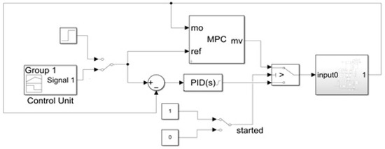
Figure 7.
Connection to the model predictive control (MPC) controller.
The tracking signal results are shown in Figure 8. It can be seen that the PID controller tracks the reference signal in a closer distance over time. In contrast, the output signal of the MPC controller maintains a certain error with the tracking signal. The relative error curves of the two controllers are presented in Figure 9. In the 12–14 s and 18–21 s intervals, the relative error of the PID controller is smaller than that of the MPC controller and varies greatly for the remaining time. The absolute error curves of the two controllers are plotted in Figure 10. Specifically, the PID controller has an increasingly larger absolute error than the MPC controller over time. This suggests that the MPC controller outperforms the PID controller in terms of accuracy and stability.
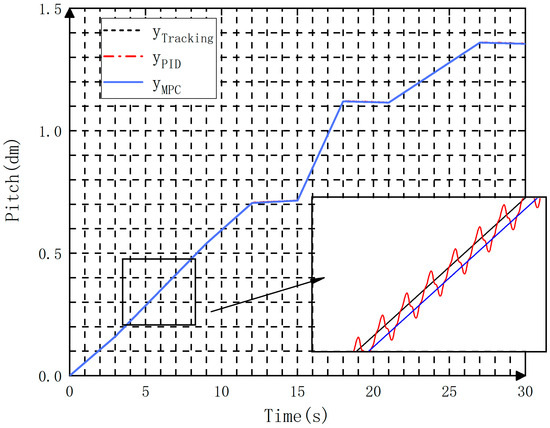
Figure 8.
Tracking signal results of the two controllers.
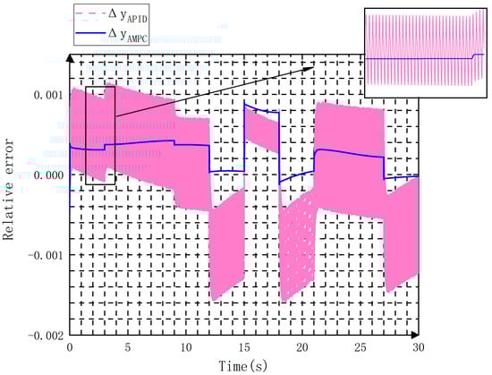
Figure 9.
Relative errors of the two controllers.
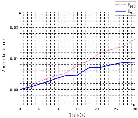
Figure 10.
Absolute errors of both controllers.
The simulation results with a step signal incorporated into the system are shown in Figure 11. Two error bands of 5% and 2% were set during the simulation. The regulation time of the MPC was 6.716 s and 6.896 s, and no overshoot was detected. The regulation time of the PID reached 6.705 s and 6.885 s, and the presence of a 1% overshoot was visible. These results indicate that the MPC had good accuracy and response speed under the step signal.
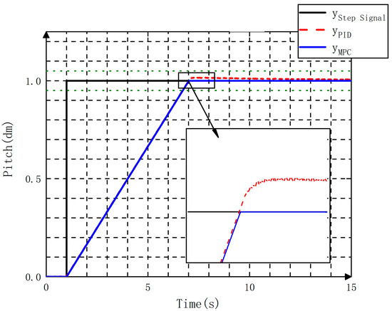
Figure 11.
Step signal outcomes of the two controllers.
4. Experimental Studies
A semi-physical simulation experiment was designed to verify the effectiveness of the MPC controller. The controllable pitch propeller was implemented in the form of a virtual prototype, and the controller used the embedded pitch control board designed in the current work. Both achieved bi-directional data communications through TCP/IP.
4.1. Virtual Prototype
The virtual prototype of the controllable pitch propeller was fabricated using three-dimensional modeling. Briefly, a specified type of controllable pitch propeller device was selected in the laboratory as a prototype. Subsequently, a three-dimensional model of its components was established using Solidworks (SolidWorks is an original 3D design software based on the Windows system). Based on the coordination relationship between the actual parts, the hub assembly, double oil pipe assembly, and oil distributor assembly were constructed. These components were assembled to form the controllable pitch propeller. Finally, the three-dimensional model was imported into the virtual experimental scene constructed using Unity3D. Unity3D is a comprehensive game development tool that allows players to easily create interactive content such as 3D video games, architectural visualizations, real-time 3D animations, and more. It is a fully integrated professional game engine. The virtual prototype is schematically illustrated in Figure 12.
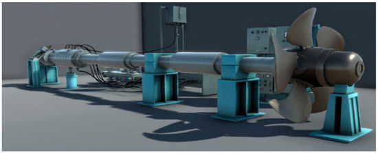
Figure 12.
Pitch paddle virtual prototype.
4.2. Hardware Design
An open STM32F4X Target system (STM32F4X is a high-performance microcontroller developed by STMicroelectronics.) was designed to establish Simulink simulation models with one-click automatic code generation and download them to the embedded development board for real-time simulation. It primarily consists of stm32f4x.tlc, stm32f4x_file_process.tlc, stm32f4x_callback_handler.m, stm32f4x_make_rtw_hook.m, as well as TLC and C files of various hardware resource drivers on the embedded board. The purpose is to set the target parameters during code generation, user code customization, Keil uVision5 invocation (Keil uVision5 is a microcontroller software development platform developed by the well-known German software company Keil.), etc. STM32F4XTarget supports the Simulink Coder and Embedded Coder with Simulink model code generation, which controls the code building through the target system file. The Keil uVision5 compiler is automatically invoked in the background to compile, link, and download the code without human intervention. This compiler can be deployed to the supporting embedded development board by clicking Build on the Simulink toolbar, and the working process is illustrated in Figure 13.
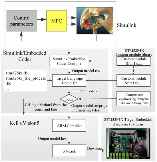
Figure 13.
STM32F4X target system workflow.
4.3. Semi-Physical Simulation Test
The virtual experiments were conducted using the virtual experiment software of the host computer, and the control experiment was initiated by clicking Start Simulation. During the simulation experiment, the simulation curve was observed through the real-time simulation curve window. According to the test needs, the controller parameters can be modified. The simulation experiment procedures are shown in Figure 14.
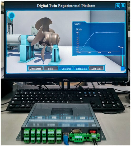
Figure 14.
Digital experimental platform.
After applying the command signal from zero pitch to positive limit pitch and negative limit pitch, respectively, the results are shown in Figure 15 and Figure 16.
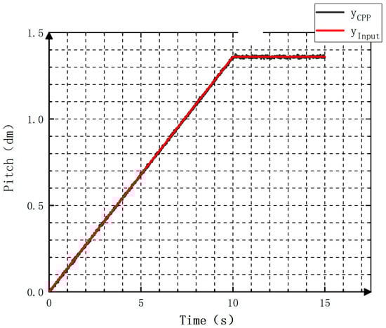
Figure 15.
Patch adjustment in the forward direction.
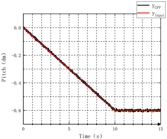
Figure 16.
Patch adjustment in the opposite direction.
According to the definitions of the relative and absolute errors, the experimental results are illustrated in Figure 17 and Figure 18 for positive pitch as well as in Figure 19 and Figure 20 for negative pitch.
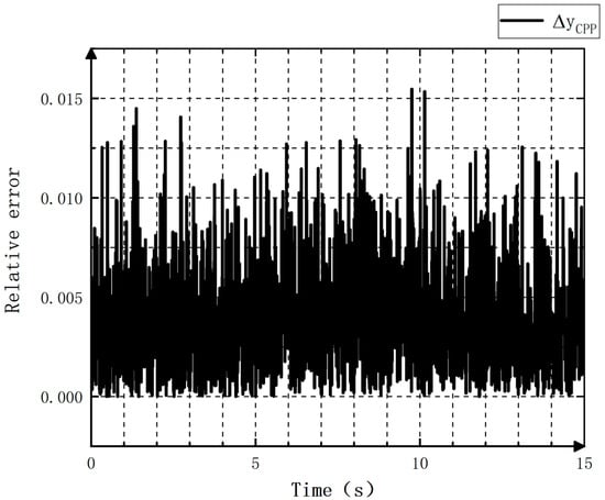
Figure 17.
Relative errors in the case of forward pitch adjustment.
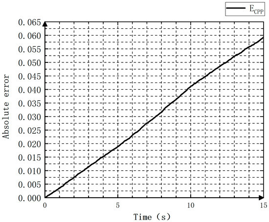
Figure 18.
Absolute errors when the pitch is undergoing adjustment in the forward direction.
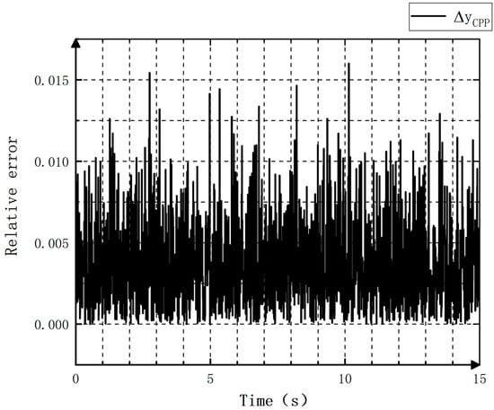
Figure 19.
Relative errors during pitch modification in the opposite direction.
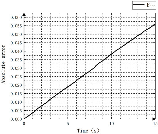
Figure 20.
Absolute errors in the case of pitch adjustment in the opposite direction.
From Figure 17 and Figure 19, it can be found that the pitch, when being adjusted by the controllable pitch propeller, exhibits a relative error within 0.002 cm. Figure 18 and Figure 20 demonstrate that in the first ten seconds, a more obvious increase is observed in the absolute error of the pitch over time. When the adjustment ends, the absolute error is not obvious, indicating the good stability of the controller.
The curve of inputting positive step signals is plotted in Figure 21. Accordingly, the pitch enters the 5% error band at 3.7 s, and no overshoot is detected. Figure 22 portrays the curve of introducing negative step signals. In this case, the pitch value falls within the 5% error band at 2.7 s. Similarly, no apparent overshoots are observed. It can be concluded that the response speed of the controllable pitch propeller controller to signals is relatively fast.
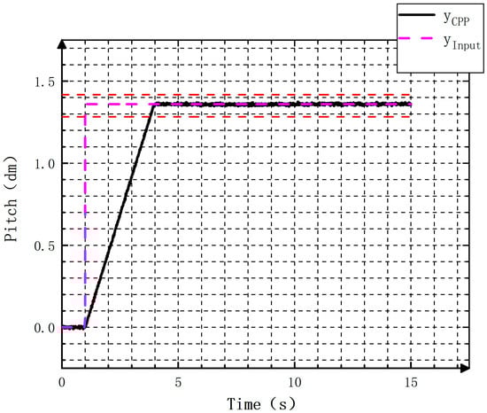
Figure 21.
Forward step curves.
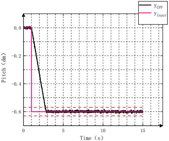
Figure 22.
Opposite step curves.
5. Conclusions
In this paper, the structural composition and working principle of a controllable pitch propeller were introduced. The controllable pitch propeller hydraulic system had the inherent features of high constraint and nonlinearity. To address this, the MPC algorithm-derived controller was designed. A physical model of the hydraulic system was established by using MATLAB/Simulink. The transfer function of the hydraulic system was derived from multiple sets of input and output data using system identification tools. The system identification simplified the mathematical modeling process for the controlled object and shorten the design cycle. Custom signal and step signal tests were conducted in the MATLAB/Simulink environment. By comparing the relative and absolute errors of the two controllers, it was found that the MPC controller displayed a shorter regulating duration, lower overshooting amount, and higher control accuracy than the traditional PID controller. Under the existing conditions, the controllable pitch propeller with controller hardware in the loop test platform was fabricated. Embedded Coder was adopted to realize the one-key generation of the embedded code. The semi-physical simulation experiment verified the stability of the designed controller, and the control algorithm ran smoothly and met the control requirements.
The crux of the model-based predictive control algorithm lies in the accuracy of the model. With the development of artificial intelligence and advanced machine learning, the data-driven method can be used to establish a more accurate mathematical model by using the real-time data of the controllable pitch propeller. On this basis, the performance of the controllable pitch propeller can be improved by changing the parameters of the model predictive control algorithm.
6. Additional Points
(1) A control law based on the MPC algorithm is designed. The MPC and PID control systems are compared and simulated to verify the effectiveness of the MPC controller. (2) The virtual prototype of the controllable pitch propeller is fabricated using three-dimensional modeling. Additionally, the embedded controller is created using the C-MEX S-Function and TLC programming language. (3) A semi-physical simulation experiment is conducted. The results show that the controllable pitch propeller with an embedded controller runs reliably and has good anti-interference, achieving the control function of the pitch propeller under various working conditions.
Author Contributions
Methodology, P.S.; software, G.C. and Y.W.; validation, P.S. and J.W.; investigation, X.F.; data curation, X.F.; writing—original draft preparation, P.S.; writing—review and editing, G.C.; funding acquisition, P.S. All authors have read and agreed to the published version of the manuscript.
Funding
This research was funded by [the Naval University of Engineering Foundation] grant number [2022502040].
Data Availability Statement
The data that support the findings of this study are available from the first author, Pan Su, upon reasonable request.
Conflicts of Interest
The authors declare that there are no conflicts of interest. The authors would like to thank the reviewers for their thoughtful, unbiased, and constructive suggestions, which contributed to this revised manuscript.
References
- Kono, M.; Murakami, Y.; Morishita, T.; Mishima, K. Decoupling Control of the Ship Propelled with a Controllable Pitch Propeller. Trans. Soc. Instrum. Control. Eng. 2009, 20, 254–259. [Google Scholar] [CrossRef][Green Version]
- Araujo, L.S.; Mendes, M.C.; de Almeida, L.H.; Dutra, M.S.; Cardoso, D. Failure of a Concentric Pipe for a Controllable Pitch Propeller System. J. Fail. Anal. Prev. 2014, 14, 55–60. [Google Scholar] [CrossRef]
- Bai, X.; Ling, H.; Luo, X.-F.; Li, Y.-S.; Yang, L.; Kang, J.-C. Reliability and availability evaluation on hydraulic system of ship controllable pitch propeller based on evidence theory and dynamic Bayesian network. Ocean. Eng. 2023, 276, 114125. [Google Scholar] [CrossRef]
- Fang, Y.; Kan, S.; Sun, K. Reliability Prediction and Analysis on Hydraulic System for Controllable Pitch Propeller of Vessels. Mach. Tool Hydraul. 2015, 13, 195–200. [Google Scholar]
- Zhang, C.J.; Li, J.; Jiang, H.G.; Chen, Y.; Yin, Y.B. Design and Analysis of a Two-Valve Control Hydraulic System for Controllable Pitch Propeller. Adv. Mater. Res. 2012, 468–471, 122–126. [Google Scholar] [CrossRef]
- Rosenkranz, H.G.; Robson, M. Control Method and Control System for a Controllable Pitch Marine Propeller. CA2543269C, 6 May 2024. [Google Scholar]
- Ji, M.; Zhao, P.; Liang, L.; Liu, P. Design and Optimization of Control System for Controllable Pitch Propeller with Load Protection. In Proceedings of the 2018 IEEE International Conference on Mechatronics and Automation (ICMA), Changchun, China, 5–8 August 2018. [Google Scholar] [CrossRef]
- Chen, H. Application of PID in Controllable Pitch Propeller of a Multipurpose Ocean Tug. Appl. Mech. Mater. 2014, 464, 253–257. [Google Scholar] [CrossRef]
- Wang, H. Application of nonlinear PID technology in the pitch controlled propeller of ship. Ship Sci. Technol. 2017, 39, 16–19. [Google Scholar]
- Sanborn, S.D.; Varshney, D.; Mcauley, K.B. Orthogonalization-Based Gain Conditioning for Linear Model Predictive Control. Ind. Eng. Chem. Res. 2023, 62, 1463–1479. [Google Scholar] [CrossRef]
- Yu, T.; Xu, Z.; Zhao, J.; Chen, X.; Biegler, L.T. A fast, fully distributed nonlinear model predictive control algorithm with parametric sensitivity through Jacobi iteration. J. Process Control. 2022, 110, 133–153. [Google Scholar] [CrossRef]
- Aboelsaud, R.; Ibrahim, A.; Aleksandrov, I.V.; Ali, Z.M. Model predictive control algorithm for fault ride-through of stand-alone microgrid inverter. Int. J. Electr. Power Energy Syst. 2022, 135, 107485. [Google Scholar] [CrossRef]
- Sun, P.; Chen, J.; Xie, L.; Su, H. Active design of dynamic GP models for model predictive control using expected improvement. Can. J. Chem. Eng. 2023, 101, 4587–4605. [Google Scholar] [CrossRef]
- Wang, C.; Liu, X.; Yang, X.; Hu, F.; Jiang, A.; Yang, C. Trajectory Tracking of an Omni-Directional Wheeled Mobile Robot Using a Model Predictive Control Strategy. Appl. Sci. 2018, 8, 231. [Google Scholar] [CrossRef]
Disclaimer/Publisher’s Note: The statements, opinions and data contained in all publications are solely those of the individual author(s) and contributor(s) and not of MDPI and/or the editor(s). MDPI and/or the editor(s) disclaim responsibility for any injury to people or property resulting from any ideas, methods, instructions or products referred to in the content. |
© 2024 by the authors. Licensee MDPI, Basel, Switzerland. This article is an open access article distributed under the terms and conditions of the Creative Commons Attribution (CC BY) license (https://creativecommons.org/licenses/by/4.0/).