Abstract
This paper proposes an S/X-band single-layer shared-aperture array antenna for the multifunction radars of military ships. A unit cell of the proposed antenna consists of one S-band element and four X-band elements. The S- and X-band elements are printed on the same layer to prevent a blockage effect by upper elements in the stacked shared-aperture antenna. Herein, the S-band element has a mutual complementary configuration for the X-band elements. In addition, the unit cell of the proposed antenna is designed in a symmetrical structure, which can be flexibly extended to a full array configuration. To verify the antenna feasibility, antenna performances are measured in a full anechoic chamber. The fractional bandwidths of the S- and X-band elements are 13.6% and 13.4%, respectively. Moreover, in the 2 × 2 array configuration, the S-band array gain in the bore-sight direction varies from 5.4 dBi to 3.5 dBi when the main beam is steered from 0° to 45°. Under the same conditions, the measured X-band array gain in the bore-sight direction decreases from 13.4 dBi to 11.6 dBi.
1. Introduction
In recent years, there has been increasing demand for the use of multifunction radar (MFR) systems in military ships. The MFR includes S- and X-band radars, which are useful for surveilling and tracking enemy targets from a long distance [1,2,3,4,5]. However, mounting the S- and X-bands separately requires a large aperture size, which increases the radar cross section (RCS) of military ships [6]. To reduce the mounting area, shared-aperture antenna technologies can be applied in the MFR, in which S- and X-band radars share a limited aperture size. Therefore, shared-aperture antenna technologies can easily reduce the RCS of the military ships compared to the other RCS reduction techniques [7,8]. In previous studies on the shared-aperture antenna, stacked structure antennas using combinations of various elements such as patches [9,10], loops [11], and dipoles [12,13], have been reported. However, in the stacked shared-aperture antenna, the upper elements electromagnetically block the lower elements. This blockage effect causes a degradation of the antenna performances in the lower elements [14]. To solve the blockage effect, a single-layer antenna configuration can be applied in which the S- and X-band elements of the shared-aperture antenna are printed on the same layer. However, in the single-layer configuration, the S- and X-band radars can physically interfere with each other because of the limited printing space. Various techniques such as using a small size radiator, diagonal array, and thinned array configuration, have been tried to solve this problem for the single-layer structure [15,16]. However, these studies do not provide sufficient antenna bandwidths for the MFR when the aperture size is limited. In addition, these antennas are not designed as a symmetrical unit cell, making it difficult to maintain the MFR through radar element replacement [17].
In this paper, we propose an S/X-band single-layer shared-aperture array antenna for the MFRs of military ships. A unit cell of the proposed antenna consists of one S-band element and four X-band elements. The S- and X-band elements are printed on the same layer to prevent a blockage effect by upper elements in the stacked shared-aperture antenna. Herein, the S-band element should have a small radiator to avoid physical interference with the X-band elements, which cause the narrow bandwidth characteristics of the S-band element. Therefore, a mutual complementary configuration for the X-band elements is applied to the S-band element, which maximizes the area for printing the radiator and improves the antenna bandwidth. To further improve the antenna bandwidth, the S-band element is separated into one feeding patch and a pair of parasitic patches. This configuration has small gaps between the feeding patch and the parasitic patches so that the antenna bandwidth can be improved by adjusting the gap size. The X-band elements are rectangular patch antennas, and the dielectric constant and thickness of the antenna substrate are determined to have a low physical interference with the S-band element and a wide antenna bandwidth of the X-band elements. In addition, the unit cell of the proposed antenna is designed in a symmetrical structure, which can be flexibly extended to a full array configuration. The proposed shared-aperture antenna with the single-layer configuration has broad bandwidths while avoiding the blockage effect compared to other previous work. Thus, this antenna design is suitable for the MFR system of military ships. To verify the antenna feasibility, antenna performances such as reflection coefficients, bore-sight gains [18], and radiation patterns are measured in a full anechoic chamber. The proposed unit cell is extended to a 2 × 2 array configuration to examine the array gains and beam-steering performance.
2. Design of a Unit Cell for the Single-Layer Shared-Aperture Antenna
Figure 1 presents the geometry of the S/X-band single-layer shared-aperture antenna for the MFRs of military ships. A unit cell of the proposed antenna consists of one S-band element and a 2 × 2 X-band array, both of which are printed on the same layer. Since this configuration does not include an upper stacked element, the performance degradation of the antenna due to the blockage effect can be prevented compared to a stacked structure antenna. Herein, the S-band patch element contains a small size radiator with a length l1 and a width w1 to avoid physical interference with the X-band elements. However, the small size radiator has narrow bandwidth characteristics [19,20]. Therefore, the S-band element consists of one feeding patch and a pair of parasitic patches, which have a mutual complementary configuration to the X-band elements. A mutual complementary configuration means that two different shapes have a maximum area without overlapping within a limited area. Therefore, this configuration can maximize the area of the radiator, which can improve the bandwidth of the S-band element. Herein, the gap size between the feeding patch and the parasitic patches is g, and the antenna bandwidth can be further improved by adjusting the gap size g. The parasitic elements have a half-cross shape obtained by combining two rectangular structures of different lengths. In this element, the long rectangle has a width w2 and a length l2, and the short rectangle has a width w3 and a length l3. The X-band elements are rectangular patch antennas with a width wx and a length lx. In general, the length of the patch antenna can be calculated using the wavelength and the dielectric constant [18]. However, because of the coupling characteristics, the length of the X-band element is adjusted more by the S-band patch parameters. To obtain the wide antenna bandwidth of the X-band elements without causing physical interference to the S-band element, an RF-60 substrate (εr = 6.05, tan δ = 0.0018) with a thickness h is applied to the proposed antenna. In addition, the unit cell of the proposed antenna is designed in a symmetrical structure, which can be flexibly extended to a full array configuration. The design parameters are obtained using the CST electromagnetic simulator [21] and are provided in Table 1.
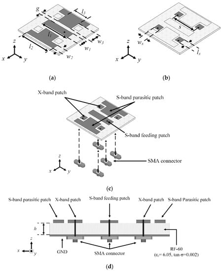
Figure 1.
Geometry of the proposed single-layer shared-aperture antenna: (a) isometric view of the S-band element; (b) isometric view of the X-band array; (c) isometric view of the unit cell; (d) side view of the unit cell.

Table 1.
Geometrical parameters of the proposed antenna.
Figure 2 illustrates the comparison of antenna performances according to the S-band element configurations. Figure 2a (Case 1) shows a small size radiator for the S-band to avoid physical interference with the X-band elements, which has narrow bandwidth characteristics. To improve the antenna bandwidth, the mutual complementary configuration can be applied to the S-band element, as shown in Figure 2b (Case 2). The use of a mutual complementary configuration for X-band elements can maximize the area of the radiator, which can improve the antenna bandwidth. To further improve the antenna bandwidth, the S-band element is separated into one feeding patch and a pair of parasitic patches, as shown in Figure 2c (Case 3). As shown in Figure 2d, the S-band element with the mutual complementary configuration including small gaps has a fractional bandwidth of 14.0%, which is 13.1% greater than that of the small size radiator, while the bore-sight gain for all cases are not significantly different.
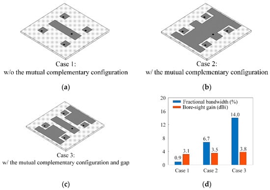
Figure 2.
Comparison of antenna performances according to S-band element configurations: (a) without the mutual complementary configuration; (b) with the mutual complementary configuration; (c) with the mutual complementary configuration and gap; (d) bandwidths and bore-sight gains according to the S-band element configuration.
Figure 3 shows the reflection coefficient according to the patch widths. The bandwidths of the S- and X-band elements increase as S- and X-band patch widths w1 and wx increase, respectively. The element widths are determined by considering the bandwidths and the average reflection coefficients.
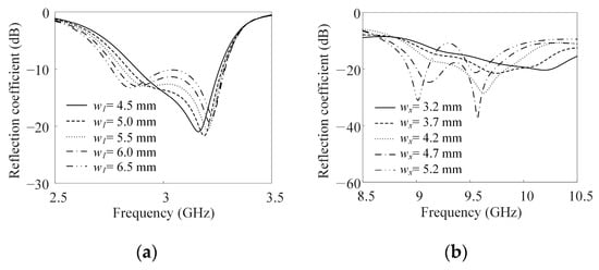
Figure 3.
Reflection coefficient according to patch widths: (a) for the S-band element; (b) for the X-band elements.
To examine the operating principles of the S-band element, this element is modeled as an equivalent circuit. Figure 4 presents the impedance characteristics of the full EM simulation (CST) and the equivalent circuit model. The equivalent circuit model is obtained using a data-fitting method [22]. In the equivalent circuit model, the feeding patch and the parasitic patches are expressed as parallel circuits using resistances (Rn), inductances (Ln), and capacitances (Cn) [23,24]. In addition, n is the element index, where n = 1 refers to the feeding patch, and n = 2, 3 refers to the parasitic patches. In addition, Lf is the feed inductance, and Cmn is the capacitive coupling between the feeding patch and the parasitic patches. The values of each lumped element are determined to minimize the difference between the impedance characteristics of the equivalent circuit and the EM simulation, as shown in Table 2. Figure 4b compares the real and imaginary characteristics of the antenna impedance of the equivalent circuit model and the full EM simulation model. In this result, averages of the real and imaginary impedance differences are 5.9 Ω and 3.4 Ω, respectively. Thus, the tendency of the impedance characteristics of the equivalent circuit model is similar to the results of the full EM simulation model. Figure 4c,d show the antenna bandwidths of the equivalent circuit model and the full EM simulation model depending on the parameters Cmn and g, respectively. As shown in Figure 4c, the bandwidth of the equivalent circuit model varies when the capacitance Cmn is adjusted. The bandwidth of the full EM simulation model is then changed by adjusting the gap g, as shown in Figure 4d. This result is similar to that demonstrated in Figure 4c. Thus, these results demonstrate that the relation between Cmn and g is similar to the tendency of the capacitance according to the distance between conductors. Furthermore, the bandwidth of the S-band element is improved by adjusting the capacitive coupling between the feeding patch and parasitic patches. Figure 5 illustrates the normalized surface current distributions of the proposed antenna. Strong surface currents are observed in both the feeding patch and the parasitic patches, which indicate that the feeding patch and parasitic patch are electrically coupled.
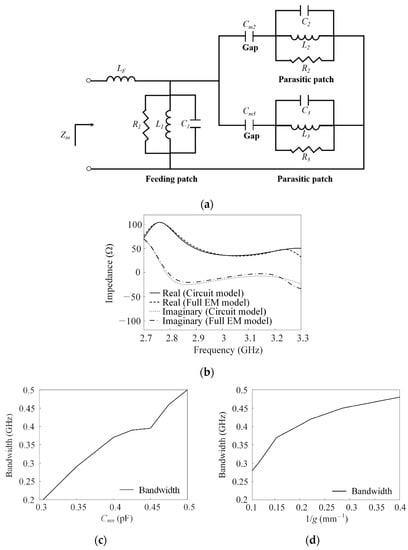
Figure 4.
Impedance characteristics of the equivalent circuit model and the full EM simulation model: (a) equivalent circuit model; (b) comparison of impedance characteristics; (c) parametric study of Cmn in the equivalent circuit model; (d) parametric study of g in the full EM simulation model.
Table 2.
Lumped element parameters of the equivalent circuit model.
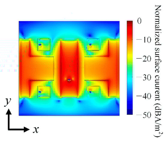
Figure 5.
Normalized surface current distributions of the S-band element.
Figure 6 shows the antenna performance variation of the X-band element according to the substrate characteristics. As shown in Figure 6a, the isolation [25,26] between the S- and X-band elements increases with the dielectric constant. However, radiation efficiency decreases as the dielectric constant increases [27]. Figure 6b represents the fractional bandwidth [25] and the front-to-back (F/B) radiation ratio of the X-band element according to the substrate thickness. The bandwidth of the X-band element increases with substrate thickness. However, because the radiation pattern of the antenna is distorted as the substrate thickness increases, the F/B radiation ratio decreases [28,29]. Therefore, considering these results, the RF-60 substrate, which has a dielectric constant of 6.05 and a thickness of 3.2 mm, is used to design the proposed antenna.
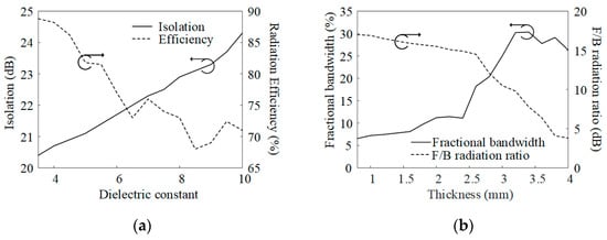
Figure 6.
Antenna performance variations of the X-band element according to the dielectric constant and the thickness of the substrate: (a) isolation and radiation efficiency according to the dielectric constant; (b) bandwidth and front-to-back (F/B) radiation ratio according to substrate thickness.
3. Measurement Results of the Proposed Antenna
Figure 7 illustrates the fabricated array antenna. The manufacturing process of the proposed antenna is as follows: The antenna radiators of the proposed unit cell (one S-band element and four X-band elements) are printed on the RF-60 substrate using etching techniques, as shown in Figure 7a. We then make holes for inserting the antenna connectors, and SMA connectors are mounted on the bottom face of the substrate for all elements. In addition, the inner conductor of the SMA connector is connected to the radiator through soldering. Finally, the unit cell of the proposed antenna is expanded to a 2 × 2 array configuration. All elements of the array have their own ports that can be connected to transmitter–receiver modules for digital beamforming, as shown in Figure 7b. The average coupling characteristics in the operating frequency are examined, and these average couplings for the nearest element are less than −10.1 dB in the S-band and −15.9 dB in the X-band. Next, antenna performances such as reflection coefficients, bore-sight gains, and radiation patterns are measured in a full anechoic chamber, as shown in Figure 7c.
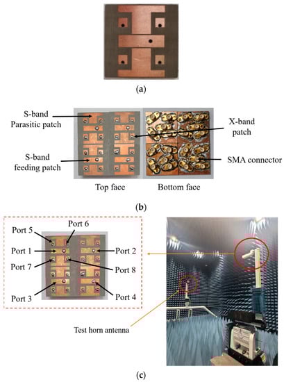
Figure 7.
Fabricated 2 × 2 array: (a) unit cell with printed radiators; (b) top and bottom faces of the 2 × 2 array; (c) measurement setup.
Figure 8 shows the reflection coefficients of the proposed antenna. The measured and simulated reflection coefficients are indicated by the solid and dashed lines, respectively. In the S-band, the measured fractional bandwidth is 13.6% (2.87 GHz to 3.28 GHz), which is in good agreement with the simulated result of 15.6%. In the X-band, the measured fractional bandwidth is 13.4% (8.60 GHz to 9.82 GHz), which is also similar to the simulated result of 14.1%.
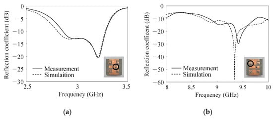
Figure 8.
Reflection coefficients of the proposed antenna: (a) for the S-band; (b) for the X-band.
To confirm the feasibility of the proposed shared-aperture antenna, the array antenna characteristics, such as a bandwidth, a bore-sight gain, array spacing, number of elements, and unit cell height, are compared with the other previous studies, as shown in Table 3. The results demonstrate that the proposed antenna has broad bandwidths with a small unit cell size compared with the other antennas in previous studies.
Table 3.
Comparison of the proposed antenna’s performances with previous studies.
Figure 9 presents the 2D radiation patterns of the individual element of the proposed antenna. In the S-band, the measured and simulated peak gains are observed in the bore-sight direction, and their values are 2.4 dBi and 3.8 dBi, respectively. In addition, the half power beam widths (HPBWs) of the S-band element in the zx- and zy-planes are 131.4°and 95.9°, respectively, which are in good agreement with the simulated HBPWs of 122.9° and 96.1°. The measured bore-sight gain for the X-band element is 2.6 dBi, which is the same as the simulation result. Herein, the direction of the main beam is slightly tilted, and the measured and simulated peak gains are 4.8 dBi and 2.7 dBi, respectively. The X-band element HPBWs in the zx- and zy-planes are 59.2° and 89.1°, respectively, which are also similar to the simulated HBPWs of 59.4° and 89.1°.
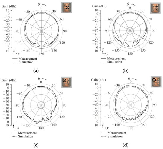
Figure 9.
2D radiation patterns of the proposed antenna: (a) S-band element in the zx-plane; (b) S-band element in the zy-plane; (c) X-band element in the zx-plane; (d) X-band element in the zy-plane.
Figure 10 represents the beam-steering performance of the 2 × 2 array configuration. To verify the beam-steering performance of the proposed antenna, the active element patterns (AEP) for all array elements are measured in a full anechoic chamber. To measure the AEP for each element of the array, a network analyzer with an RF cable is connected to only one element, and all other elements are terminated. After repeating this procedure for all elements, the total array gain of the proposed antenna is calculated using the obtained AEPs based on the following equation [30,31]:
where vn and wn represent the complex AEP vector and the weighting vector of the nth element, respectively. In the S-band, the array gains in the bore-sight direction based on the measurement and simulation are 5.4 and 6.1 dBi, respectively. Furthermore, the maximum gain varies from 5.4 dBi to 3.5 dBi when the main beam is steered from θ = 0° to 45°. In the X-band result, the measured array gain in the bore-sight direction is 13.4 dBi, which is in good agreement with the simulation result of 14.5 dBi. Herein, the bore-sight gain decreases from 13.4 dBi to 11.6 dBi under the same beam-steering conditions. Figure 11 shows the total active reflection coefficients (TARCs) [32] and the envelope correlation coefficients (ECCs) [33] of the proposed 2 × 2 array. The average TARCs for Port 1 and Port 8 (port numbers are marked in Figure 5) are observed when the main beam is steered from θ = 0° to 45°. The average TARCs are −9.5 dB in the S-band and −11.8 dB in the X-band, as shown in Figure 11a,b. In addition, the ECCs for the S-band (from Port 1 to Port 4) and for the X-band (from Port 5 to Port 8) are also examined. The average ECCs for the nearest element are observed as 0.07 in the S-band and 0.002 in the X-band, as shown in Figure 11c,d. The result demonstrates that the proposed shared-aperture antenna is suitable for MFR applications.
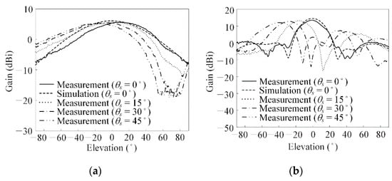
Figure 10.
Beam-steering characteristics of the proposed antenna: (a) S-band; (b) X-band.
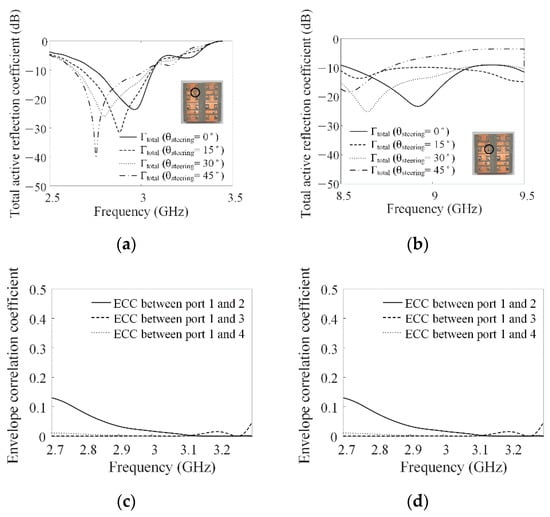
Figure 11.
Total active reflection coefficient and envelope correlation coefficient (a) total active reflection coefficients in the S-band; (b) total active reflection coefficients in the X-band; (c) envelope correlation coefficients in the S-band; (d) envelope correlation coefficients in the X-band.
4. Conclusions
We investigated the S/X-band single-layer shared-aperture array antenna for the MFRs of military ships. The unit cell of the proposed antenna consisted of one S-band element and four X-band elements, which were printed on the same layer to prevent the blockage effect by the upper element in the stacked shared-aperture antenna. To improve the S-band antenna bandwidth, the S-band element consisted of one feeding patch and a pair of parasitic patches, which is a mutual complementary configuration to the X-band elements. The unit cell was extended to the 2 × 2 array configuration to examine of the array gains and beam-steering performances. The antenna bandwidths of the S- and X-band elements were 13.6% and 13.4%, respectively. The array gains of the S- and X-bands in the bore-sight direction based on the measurement were 5.4 and 13.4 dBi, respectively. The maximum gain of the S-band element varied from 5.4 dBi to 3.5 dBi when the main beam was steered from 0° to 45°. Under the same conditions, the bore-sight gain decreased from 13.4 dBi to 11.6 dBi in the X-band. The result demonstrated that the proposed shared-aperture antenna is suitable for MFR applications.
Author Contributions
Conceptualization, E.-Y.Y., D.J., C.-H.L. and H.C.; Formal analysis, E.-Y.Y., D.J. and H.C.; Investigation, E.-Y.Y. and D.J.; Methodology, E.-Y.Y., D.J., C.-H.L. and H.C.; Project administration, H.C.; Resources, E.-Y.Y., D.J., C.-H.L. and H.C.; Software, E.-Y.Y. and D.J.; Supervision, H.C.; Validation, E.-Y.Y., D.J. and H.C.; Visualization, E.-Y.Y. and D.J.; Writing—original draft, E.-Y.Y. and D.J.; Writing—review & editing, E.-Y.Y., D.J. and H.C. All authors have read and agreed to the published version of the manuscript.
Funding
This research received no external funding.
Institutional Review Board Statement
Not applicable.
Informed Consent Statement
Not applicable.
Data Availability Statement
Not applicable.
Acknowledgments
This research has been supported by the Challenging Future Defense Technology Research and Development Program (9127786) of Agency for Defense Development in 2019.
Conflicts of Interest
The authors declare no conflict of interest.
References
- Wang, A.; Krishnamurthy, V. Signal interpretation of multifunctional radars: Modeling and statistical signal processing with stochastic context free grammar. IEEE Trans. Signal Process. 2008, 56, 1106–1119. [Google Scholar] [CrossRef]
- Zhou, Y.; Wang, T.; Hu, R.; Su, H.; Siu, Y.; Suo, J.; Snoussi, H. Multiple kernelized correlation filters (MKCF) for extended object tracking using X-band marine radar data. IEEE Trans. Signal Process. 2019, 67, 3676–3688. [Google Scholar] [CrossRef]
- Kwon, G.; Park, J.Y.; Kim, D.H.; Hwang, K.-C. Optimization of a shared-aperture dual-band transmitting/receiving array antenna for radar applications. IEEE Trans. Antennas Propag. 2017, 65, 7038–7051. [Google Scholar] [CrossRef]
- Wang, S.; Jang, D.; Kim, H.; Kim, H.; Choo, H. Design of polarization-selective EM transparent mesh-type E-shaped antenna for shared-aperture radar application. Appl. Sci. 2022, 12, 1862. [Google Scholar] [CrossRef]
- Choo, J.; Lim, T.; Kim, Y.; Choo, H. Design of wideband printed patch dipole antenna with a balanced on-board feeding network. J. Electromagn. Eng. Sci. 2022, 22, 631–637. [Google Scholar] [CrossRef]
- Tavik, G.C.; Hilterbrick, C.L.; Evins, J.B.; Alter, J.J.; Crnkovich, J.G.; Degraff, J.W.; Habicht, W.; Hrin, G.P.; Lessing, S.A.; Wu, D.C.; et al. The advanced multifunction RF concept. IEEE Trans. Microw. Theory Tech. 2005, 53, 1009–1020. [Google Scholar] [CrossRef]
- Liu, T.; Gao, X.; Zheng, Q.; Li, W.; Yang, H. RCS reduction of waveguide slot antenna with metamaterial absorber. IEEE Trans. Antennas Propag. 2013, 61, 1479–1484. [Google Scholar] [CrossRef]
- Dikmen, C.M.; Çimen, S.; Çakır, G. Planar octagonal-shaped UWB antenna with reduced radar cross section. IEEE Trans. Antennas Propag. 2014, 62, 2946–2953. [Google Scholar] [CrossRef]
- Bai, C.X.; Cheng, Y.R.; Ding, Y.R.; Zhang, J.F. A metamaterial-based S/X-band shared-aperture phased-array antenna with wide beam scanning coverage. IEEE Trans. Antennas Propag. 2020, 68, 4283–4292. [Google Scholar] [CrossRef]
- Kim, J.-H.; Hong, S.K.; Kim, B.-G. A shared-aperture S/X dual broadband microstrip antenna with one perforated patch. Microw. Opt. Technol. Lett. 2019, 62, 507–513. [Google Scholar] [CrossRef]
- Mao, C.-X.; Gao, S.; Wang, Y.; Luo, Q.; Chu, Q.-X. A shared-aperture dual-band dual-polarized filtering-antenna-array with improved frequency response. IEEE Trans. Antennas Propag. 2017, 65, 1836–1844. [Google Scholar] [CrossRef]
- Cheng, Y.; Dong, Y. Dual-broadband dual-polarized shared-aperture magnetoelectric dipole antenna for 5G applications. IEEE Trans. Antennas Propag. 2021, 69, 7918–7923. [Google Scholar] [CrossRef]
- Lu, X.; Chen, Y.; Guo, S.; Yang, S. An electromagnetic-transparent cascade comb dipole antenna for multi-band shared-aperture base station antenna array. IEEE Trans. Antennas Propag. 2022, 70, 2750–2759. [Google Scholar] [CrossRef]
- Rocio, R.-C.; Shuai, Z.; Kun, Z.; Gert, F. Reduction of main beam-blockage in an integrated 5G array with a metal-frame antenna. IEEE Trans. Antennas Propag. 2019, 67, 3161–3170. [Google Scholar]
- Song, C.-M.; Lim, H.-J.; Som, S.-V.; Lee, K.-Y.; Yang, Y.; Hwang, K.-C. Dual-band RF wireless power transfer system with a shared-aperture dual-band Tx array antenna. Energies 2021, 14, 3803. [Google Scholar] [CrossRef]
- Coman, C.I.; Lager, I.E.; Ligthart, L.P. The design of shared aperture antennas consisting of differently sized elements. IEEE Trans. Antennas Propag. 2006, 54, 376–383. [Google Scholar] [CrossRef]
- Wang, S.; Jang, D.; Kim, Y.; Choo, H. Design of S/X-band dual-loop shared-aperture 2 × 2 array antenna. J. Electromagn. Eng. Sci. 2022, 22, 319–325. [Google Scholar] [CrossRef]
- Balanis, A. Antenna Theory Analysis and Design, 4th ed.; Wiley: Hoboken, NJ, USA, 2016; pp. 61–915. [Google Scholar]
- Best, S.R. A discussion on the quality factor of impedance matched electrically small wire antennas. IEEE Trans. Antennas Propag. 2005, 53, 502–508. [Google Scholar] [CrossRef]
- Capek, M.; Gustafsson, M.; Schab, K. Minimization of antenna quality factor. IEEE Trans. Antenna Propag. 2017, 65, 4115–4123. [Google Scholar] [CrossRef]
- CST Studio Suite, DASSAULT SYSTEMS. Available online: https://www.3ds.com/products-services/simulia/products/cst-studio-suite/ (accessed on 14 January 2023).
- Kang, M.; Choo, H.; Byun, G. Design of a dual-band microstrip loop antenna with frequency-insensitive reactance variations for an extremely small array. IEEE Trans. Antennas Propag. 2017, 65, 2865–2873. [Google Scholar] [CrossRef]
- Ansari, J.A.; Ram, R.B. Analysis of broad band U-slot microstrip patch antenna. Microw. Opt. Technol. Lett. 2008, 50, 1069–1073. [Google Scholar] [CrossRef]
- Caratelli, D.; Cicchetti, R.; Bit-Babik, G.; Faraone, A. Circuit model and near-field behavior of a novel patch antenna for WWLAN applications. Microw. Opt. Technol. Lett. 2006, 49, 97–100. [Google Scholar] [CrossRef]
- Pozar, D.M. Microwave Engineering, 4th ed.; Wiley: Hoboken, NJ, USA, 2012; pp. 248–322. [Google Scholar]
- Barba, M. A high-isolation, wideband and dual-linear polarization patch antenna. IEEE Trans. Antennas Propag. 2008, 56, 1472–1476. [Google Scholar] [CrossRef]
- Colburn, J.S.; Rahmat-Samii, Y. Patch antennas on externally perforated high dielectric constant substrate. IEEE Trans. Antenna Propag. 1999, 47, 1785–1794. [Google Scholar] [CrossRef]
- Dahele, J.; Lee, K. Effect of substrate thickness on the performance of a circular-disk microstrip antenna. IEEE Trans. Antennas Propag. 1983, 31, 358–360. [Google Scholar] [CrossRef]
- Kim, J.; Kim, B.-G. Effect of feed substrate thickness on the bandwidth and radiation characteristics of an aperture-coupled microstrip antenna with a high permittivity feed substrate. J. Electromagn. Eng. Sci. 2018, 18, 101–107. [Google Scholar] [CrossRef]
- Pozar, D.M. The active element pattern. IEEE Trans. Antennas Propag. 1994, 42, 1176–1178. [Google Scholar] [CrossRef]
- Kang, E.; Lim, T.; Park, S.; Choo, H. Design of a novel wideband leaf-shaped printed dipole array antenna using a parasitic loop for high-power jamming applications. Sensors 2021, 21, 6882. [Google Scholar] [CrossRef]
- Chae, S.; Oh, S.-K.; Park, S.-O. Analysis of mutual coupling, correlations, and TARC in WiBro MIMO. IEEE Antennas Wirel. Propag. Lett. 2007, 6, 122–125. [Google Scholar] [CrossRef]
- Gao, P.; He, S.; Wei, X.; Xu, Z.; Wang, N.; Zheng, Y. Compact printed UWB diversity slot antenna with 5.5-GHz band-notched characteristics. IEEE Antennas Wirel. Propag. Lett. 2014, 13, 376–379. [Google Scholar] [CrossRef]


Disclaimer/Publisher’s Note: The statements, opinions and data contained in all publications are solely those of the individual author(s) and contributor(s) and not of MDPI and/or the editor(s). MDPI and/or the editor(s) disclaim responsibility for any injury to people or property resulting from any ideas, methods, instructions or products referred to in the content. |
© 2023 by the authors. Licensee MDPI, Basel, Switzerland. This article is an open access article distributed under the terms and conditions of the Creative Commons Attribution (CC BY) license (https://creativecommons.org/licenses/by/4.0/).