Abstract
Due to their exceptional structural integrity, steel pipelines are the main component for oil and gas transmission. However, these pipelines are often affected by corrosion, despite corrosion protection, because of harsh working conditions. In addition to corrosion defects, pipelines are often subjected to multiple external loads. The combination of corrosion defects and external loads can significantly reduce the failure pressure, resulting in various failure behaviors. This reduction in failure pressure is especially critical in pipe bends as they are the weakest link in a pipeline. This paper presents an overview of the failure behavior of corroded steel pipe components subjected to internal pressure and axial compressive stress.
1. Introduction
The rising demand for raw materials has compelled industries to exploit resources in remote locations [1]. As such, the transportation of fluid substances from such locations is facilitated by pipeline networks which have been well-established as the safest and most cost-effective mode of transportation in the industry [2,3,4,5,6,7]. Steel pipelines have been used for decades due to their outstanding structural integrity. Underground steel pipes are regarded as the most efficient transport medium for the long-distance transmission of fluids at high temperatures and pressures [8]. However, depending on the soil conditions, some pipelines are constructed aboveground. As pipelines pass through different terrains, the sophisticated network of pipes is designed to channel fluid in different directions. To achieve this, pipe bends are used at specified locations to alter the flow direction of the flowing fluid.
The influence of axial compressive stress on a pipe has proven to be the most significant among other external loads [9,10,11,12]. This condition, coupled with pipe corrosion, which is the most common and detrimental problem with steel pipes, results in a significant loss of pipe integrity [11,12]. Generally, steel pipelines have high yield strengths, leading to high allowable stresses. It is common to utilize pipes with yield strengths as high as 80% of the ultimate tensile strength. Despite the outstanding mechanical properties of steel pipelines, they experience various types of corrosion. The continued usage of these corroded pipes may lead to an overall reduction in the pipeline structural integrity, resulting in reduced failure pressure. In particular, pipe bends are most susceptible to failure, and are often regarded as the weakest link, as they experience unbalanced thrust forces due to the differences in the surface area of the intrados and extrados. The highest stress concentrations generally occur at the affected area’s deepest point [13,14,15].
The electrochemical reactions that occur in the presence of electrolytes cause corrosion in pipelines [9]. Since this process is of an electrochemical nature, it also favors the detection and mitigation of the degradation of the pipe wall by current and voltage monitoring, which is associated with the corrosion rate [5]. Both external and internal factors govern the corrosion rate of a pipeline [16]. An increase in the electrolyte concentration, coupled with harsh operating conditions, results in an increased rate of corrosion.
There are various types of corrosion, such as uniform general corrosion [15,16], galvanic corrosion [15], pitting corrosion [16], and crevice corrosion [15]. However, in this review, only uniform general corrosion is addressed. Uniform general corrosion is the simplest type of corrosion, where there is a uniform metal loss rate over an exposed surface. Uniform general corrosion is characterized as the metal loss of a region with a length and width exceeding three times the full-wall thickness. Within uniform general corrosion, there are two distinct types of corrosion: single corrosion and multiple interacting corrosion defects.
For single corrosion defects, pipe failure is said to occur when disruption occurs at the defect region and the pressurized fluid begins to tear or crack through the remaining thin ligament of the pipe. For multiple interacting corrosion defects, the failure occurs when stress and strain disruptions occur on at least one of the corrosion defects. Each corrosion defect imposes its stress and strain disturbances. The regions of expansion of stress and strain disturbances are known as regions of influence of corrosion defects. Overlapping regions of influence due to adjacent interacting corrosion defects may cause a decrease in the failure pressure [17].
2. Axial Compressive Stress
A steel pipeline may be subjected to various external loads such as hydrodynamics stresses, axial stresses, and external collapse pressures. Past studies [18] have shown that external loads cause a higher reduction in the failure pressure of a pipe. This review will focus on the most important external load, the axial compressive stress. Axial compressive stress occurs when a pipeline moves [19,20,21,22], especially in buried pipes, as large portions of the pipes are only restrained by soil friction, whereas above-ground pipelines are generally restrained by anchors and guides. The increase in the hydrocarbon demand also encourages hydrocarbon to be explored in areas with unpredictable geotechnical conditions, such as the Subarctic and the Arctic regions. These regions often see active landslides and geotechnical movements, which may cause axial compressive stresses on these pipelines [21,22,23,24,25,26,27].
Pipe bends, the weakest link of the piping system, are subjected to the Bourdon effect. The bending moment results in the opening of the pipe elbow, which subjects the pipe to ovalization. As a result, the pipe experiences axial compressive stress and tensile stress. The former has a more significant impact on the pipeline’s integrity [28,29].
2.1. Poisson’s Effect Due to Temperature Changes
Euler-bar buckling poses a risk, especially in conditions with high pressure and high operational temperature [30]. It occurs in both buried and unburied pipelines [30] and is caused by the frictional restraint of thermal expansion due to the variation in temperature or internal pressure. The types of buckling mechanisms include (1) inward-diamond buckling, where the pipe shows a single inward bulge (kink); (2) inward/outward-diamond buckling, where the pipe shows a single outward bulge with continued deformation resulting in a large outward depression with two small inward depressions; and (3) outward bulge buckling, where the pipe has from one up to four ripples (wrinkles) at the compressive side of the specimen. This occurs in the Arctic and Subarctic regions [22].
A study by Roy et al. [31] showed that axial compressive stress due to constrained thermal expansion results in the significant decrease in the pipe’s load-carrying capacity due to severe local wrinkling. Another study by Soares et al. [20] on X80 steel pipe revealed that interacting corrosion defects are more suspectable to axial compressive stress due to thermal expansion, with up to a 10% decrease in the failure pressure compared to when the pipes were subjected to internal pressure only. The study also noted that the increase in operating temperature (25–125 °C) caused changes in the stress field, the compressive stress field in the axial direction, which influenced the failure pressure.
For restrained pipes, a force is required to maintain its original position from its free expanded or contracted position. Peng [19] found that the restrained portion of a pipe would be subjected to axial compressive stresses when there is a moderate increase in transport fluid temperature, , compared to the nominal environment temperature, . The pipe section undergoes expansion equal to while the hoop tensile stress results in a shrinkage equal to . This shrinkage is governed by Poisson’s ratio and is also referred to as a Poisson shrinkage. By subtracting the Poisson’s shrinkage from the expansion, the net expansion is given by Equation (1):
The axial stress produced is equivalent to the stress required to compress back to the original position. Since , Equation (1) can be expressed as Equation (2):
For the unrestrained portion of the pipe, it was stated that there were two groups of stress: self-limiting and sustained stress. Self-limiting stress from thermal stress (and other strains) is given by Equation (3), whereas the bending stress is given by Equation (4):
Expansion due to the pressure effect (not pressure stress, which is not included in expansion stress calculations) is significant and should not be ignored. When the pipe is exposed to transport fluid temperature, , it undergoes expansion in every direction. For the unrestrained portion of the pipe, the thermal expansion in the longitudinal direction is . When subjected to longitudinal pressure, the pipe expands in the longitudinal direction but shrinks somewhat in the diametrical direction. Finally, adding radial pressure (hoop stress), the pipe expands fully in the diametrical direction but shrinks in the longitudinal direction due to the Poisson effect. The net longitudinal expansion, , is equal to:
Since strain, we have:
The calculated strain, , is in inches per inch unit.
2.2. Geological Movements
For thin pipes, radial and shear stresses are neglected, as circumferential and axial stresses are the main stresses affecting the pipe [32]. Ground movement due to earthquakes (e.g., active reverse fault), landslides, and frost heaves induce external axial force on the pipelines. Generally, a steel pipeline in direct tension due to fault rupture can safely accommodate a larger fault offset value compared to when it is strained in direct compression [18,19]. Although good engineering practice is not to lay pipelines on volatile soils, nevertheless, adjacent soil movements affect a pipeline. Often, these soil movements are relatively small, but the effects may be large enough to affect the pipeline performance [33].
Under compressive geological movement, pipeline behavior would be dominated by global and local buckling [34]. Axial bending of the corroded pipe region results from a differential settlement, or in the Arctic regions, the freeze-thaw action of permafrost regions coupled with axial compressive loading from the constraint due to the thermal expansion that exists when transporting high-temperature petroleum products [35]. A report by the Transportation Safety Board of Canada [36] revealed that some steel pipeline failures caused by axial compressive stress are due to slope movements and landslides. An example of such failure is one in 1997 when a pipeline in British Columbia, Canada ruptured, as it was subjected to excessive axial compressive stress due to soil movement in the axial direction [36]. The external loads due to soil often pose several types of stresses on pipes, namely radial, shear, circumferential, and axial stresses.
2.3. Bourdon Effect Due to Internal Pressure
As the fluid travels across the pipe component, pipe bends are subjected to internal pressure. The difference in the surface area of the pipe bend at the intrados and extrados results in unbalanced thrust forces [37,38]. These forces contribute to large stress concentrations on the wall of the pipe bend, resulting in the deformation of the cross-section of the pipe bend [28,39]. In the industry, the CSA-Z662 standard is used to assess the influence of internal pressure on a pipe bend. The Tresca stress distribution is one of the criteria used for assessment. According to the Tresca criterion, plastic deformation occurs when the maximum shear stress at a point of interest reaches the maximum stress in a uniaxial tension material at yield. Abdulhameed et al. [29] showed that the maximum Tresca stress is located at the intrados of the pipe bend, while the minimum is at the extrados, as illustrated by Figure 1. This study showed that the Bourdon effect results in an in-plane bending moment for pipe bends with fixed ends.
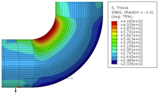
Figure 1.
Tresca stresses on a 90° pipe elbow. (Reprinted/adapted with permission from [29]).
In the presence of a bending moment acting on a pipe bend, the pipe component is subjected to axial forces above the neutral axis, as illustrated in Figure 2. As a result, a resultant force which displaces the cross-section away from the neutral axis is created. This is known as the ovalization of the pipe bend’s cross-section when subjected to internal pressure.
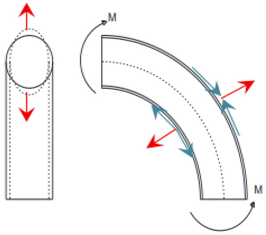
Figure 2.
Ovalization of a pipe bend under opening bending moment [29].
Ovalization results in the internal surface of the pipe wall being subjected to tension while the external surface is subjected to axial compressive stress. The surface area of the pipe wall at the extrados is acted upon by a thrust force, displacing it away from the neutral axis, causing a reduced ovalization effect at this region. As a result, the maximum impact of ovalization is observed at the intrados of the pipe bend.
The effects of axial compressive stress resulting from the ovalization of a pipe bend are more significant than the tensile stresses acting on the pipe [38]. Under this condition, the pipe bends are more susceptible to local buckling and failure.
3. Pipeline Residual Strength Assessment Methods
Chen et al. [40] showed that corrosion defects subjected to axial compressive stress result in noticeable failure pressure differences. Therefore, simplifications made to corrosion assessment methods whereby axial compressive stress is considered to have little or no effect on pipe failure are inaccurate. For instance, Netto et al. [41] showed that ASME B31G did not consider the effects of end loads (i.e., tensile loads during close-ended tests), which would result in conservative failure pressure predictions.
The exclusion of axial compressive stress influence in conventional standards and codes for the corrosion assessment methods of pipe bends also results in a highly conservative and inaccurate evaluation. Existing assessment methods only incorporate internal pressure during corrosion assessments. In addition, the research on developing corrosion assessment methods for pipe bends subjected to internal pressure and axial compressive stress is minimal. Hence, for such cases, FEM is used. In recent studies, FEM has been incorporated with ANN to develop new assessment methods that are highly accurate for corroded pipe components subjected to internal pressure and axial compressive stress [2,3,4,8,9,11,12,42,43,44,45].
3.1. DNV-RP-F101
DNV-RP-F101 (DNV) is a corrosion assessment method that was developed by Det Norske Veritas. DNV is the least conservative method for predicting the burst pressure of corroded pipelines [13,16,46] for single, interacting, and complex-shaped defects subjected to internal pressure only, and single defects subjected to both internal pressure and longitudinal compressive stress. DNV states that the source of the longitudinal compressive stress may be due to longitudinal loads, bending loads, temperature loads, etc. DNV provides two alternative methods for determining the burst pressure of corroded pipes.
The first method is known as DNV Part A. It has calibrated safety factors while considering the natural variation in pipe material properties, wall thickness, and internal pressure applications. Uncertainties associated with the dimension of the corrosion defect are explicitly considered in the determination of the pressure resistance (capacity). Probabilistically calibrated equations (with partial safety factors) are utilized for predicting the burst pressure of corroded pipelines. Equation (7) shows the DNV Part A equation with respective partial safety factors and fractile levels.
The geometry factor and the modified version of the depth over the full wall thickness ratio are given by Equations (8) and (9), respectively.
The second method, DNV Part B, is based on the Allowable Stress Design approach. The predicted burst pressure using Equation (10) is multiplied by a single usage factor based on the original design factor, as per Equation (11). Uncertainties associated with pipe material properties, pipe dimensions, and the dimensions of the corrosion defect are left to the user’s discretion.
3.2. Finite Element Methods
Timoshenko described the elastic-plastic buckling of pipes under external pressure [47]. In recent years, non-linear finite element analysis has been used as an accurate tool to predict the buckling collapse capacity of pipes under external pressure, bending, and axial force [48].
Vitali and Bruschi [10] found that finite element methods (FEMs) such as ABAQUS and ANSYS gave reliable results compared to experimental results, especially in terms of predicting buckling modes and the bending-moment vs. curvature relations. This is possible with the proper application of FEM settings, such as ensuring large deformation effects, material non-linearities, strain anisotropy, and kinematic hardening [49].
The application of finite element techniques also improves current industrial corrosion assessment guidelines by reducing excessive conservatism [31]. However, it has been noted that in cases with axial compressive stress, FEM predictions only improve with decreasing axial compressive stress. This is attributed to the coarse meshing used to model the length of the pipe (excluding the corrosion defect), which may lead to wrinkles that adversely affect the accuracy of FEM predictions. The difference in the failure pressure prediction is often due to various limit loads set to determine the point of rupture. For wrinkling, failure is predicted when the resisting moment decreases with increasing deformation [35].
3.3. Artificial Neural Networks
An Artificial Neural Network (ANN) is a powerful prediction tool in machine learning that can result in highly accurate predictions [3]. They are nonlinear systems modelled efficiently using an interconnected complex assembly of nodes that utilize supervised learning algorithms to learn from a training database by recognizing and inferring from patterns without requiring an explicit set of instructions [50]. Over the past decade, the use of ANN in pipe integrity assessment has become increasingly popular.
Tohidi and Sharifi [45] developed a back-propagation neural network (BPNN) with three layers for the assessment of residual load bearing capacity of steel plate girder ends with local corrosion using data generated from FEA. This approach resulted in accurate structural integrity assessments with a minimal error margin (within 2%). Based on the developed BPNN, an empirical equation was established for the assessment of the structure. Following this approach, Li et al. [42] developed an ANN for the vulnerability assessment of underground urban gas pipelines. In this study, the application of ANN was assessed against a support vector machine (SVM). Although it was concluded that SVM resulted in a more accurate assessment of the structure, the ANN also resulted in an acceptable error percentage of 8.64%. This error percentage can be drastically reduced by increasing the number of training data.
Chin et al. [11] developed an ANN for the failure pressure assessment of corroded pipes with a single corrosion defect subjected to internal pressure only based on burst test results of corroded pipe grades ranging from API 5L X42 to X100. A total of 71 datasets were utilized for the training of the developed ANN with 1 hidden layer (with 30 neurons). Based on the results of this study, it was revealed that the ANN predicts the failure pressures with a R-squared value of 0.99.
In line with these approaches, various researchers have developed ANNs for the integrity assessment of steel structures. In this approach, new assessment methods have been developed by integrating FEM and ANN. As ANNs require a large set of training data, FEM is used as a data generation tool. The data from the FEA is then used to train the ANN, which results in highly accurate results for assessing corroded pipes subjected to internal pressure and axial compressive stress [3].
Vijaya Kumar et al. [2,9,12,43,44] developed an empirical failure pressure assessment method for the failure pressure of corroded mid- to high-strength steel straight pipes with single defects [12], and longitudinally [43] as well as circumferentially [9] aligned the interacting defects subjected to internal pressure and axial compressive stress utilizing training data generated by FEA. In their assessment, the failure pressure was assessed as a function of the defect geometry and axial compressive stress acting on the pipe. For single corrosion defects, the developed empirical failure pressure equations were as a function of the defect depth and length and the axial compressive stress acting on the pipe. As for corroded pipes with interacting corrosion defects, the developed empirical failure pressure equations were as a function of the defect depth, length, and spacing, and the axial compressive stress acting on the pipe. The developed equations resulted in failure pressure predictions that were highly accurate with a R-squared value of 0.99. Following this approach, Liu et al. [8] studied the application of ANN for the failure pressure prediction of underground high-strength steel (HSS) pipes that developed stray current corrosion defects.
Lo et al. [51] developed an ANN to assess the failure pressure of corroded mid- to high-strength steel straight pipes with a single defect subjected to internal pressure and axial compressive stress utilizing training data generated by FEA. The developed ANN resulted in failure pressure predictions with an R-squared value of 0.99. The failure pressure assessment considers the defect depth, length, and axial compressive stress acting on the pipe.
4. Effects of Axial Compressive Stress
If the axial compressive stress is significant, the failure pressure of the pipe will be adversely affected [10,12,21,52]. An axial compressive stress may result in a longitudinal failure. Failure modes such as wrinkling and buckling can also be expected [18]. These failure modes prevent inline inspection gauges or tools from passing, resulting in pipeline operational failure [21]. When tensile loads are applied axially, the effect on the failure pressure reductions is generally small, while axially applied compressive loads can cause distinct failure pressure reductions [13,16,18,53].
4.1. Detrimental Effects
Axial compressive stress due to thermal expansion results in Euler-bar buckling. The peak bending moment corresponds to the maximum point of the bending moment-curvature relationship. This peak is triggered by the development of wrinkling and bulging of the pipe at the compressive side of the specimen [30]. Yoosef-Ghodsi et al. [54] found that the initiation of wrinkling always coincides with the maximum bending moment. The initiation of wrinkling is where the non-uniform deformation begins. Non-uniform deformation is determined when the strain in the region of wrinkle increases faster than the strain away from the wrinkle. The maximum bending moment decreases with the decrease in the material hardening ability and an increase in the outer diameter to thickness ratio.
A study conducted by Smith et al. [49] revealed wrinkling where the pipe showed an excessive loss in bending stiffness during the application of compressive bending loads before the rupture of the pipe. Wrinkling is said to occur when the peak moment is achieved. A zero slope indicates this peak moment at the moment versus the deflection behavior. It is directly affected by the wall loss in the maximum bending region and the magnitude of the internal pressure, axial compression (or tension), and axial bending. Smith et al. (1998) [48] conducted 20 full-scale tests on X65, which is 60 feet in length with 48-inch diameter pipe sections with a 0.462-inch wall thickness, to further study this detrimental effect. For each wrinkling test, only a moderate temperature difference (equal to 75 °F) was investigated. This value reflects the reduction in transported crude temperature observed over the pipeline’s lifetime and since the initiation of full-scale testing. The sequence of load application for each test was designed to simulate a pipe in service. Wrinkling was produced in test cases exhibiting extreme depths and general corrosion where the major dimension was oriented in the hoop direction. Close examination of the results for these cases, as reported in Smith et al. [55], showed that the wrinkling instability point strongly corresponded to the depth and width of corrosion defect parameters and the initial pressure and temperature differential applied.
Bai et al. [48] found that corrosion defects might cause a reduction in the hoop buckling capacity of the pipe. This is because buckling, defined as an equilibrium problem, occurs when the external loads subjected to the pipe are higher than or equal to the internal resistance over the cross-section. The external loads here refer to the axial compression acting on the cross-section. Amplification of the external stress occurs due to imperfections such as initial deflection from the circular shape and the axial compression stress acting on the pipe wall. This amplification of external stress is not be affected by local corrosion defects unless the dimensions of the corrosion defects are very wide and deep.
Experimental research by Dewanbabee and Das [21] on API 5L X46 steel pipes with artificially machined single corrosion defects subjected to 20% and 40% of while being subjected to axial compressive stress found that the load capacity (the ability to withstand axial compressive force) started to decrease due to the initiation and growth of wrinkling at the corrosion defect region. The wrinkle was noted to be an outward bulge-type local buckle at the pipe wall, as shown in Figure 3. The load capacity was the lowest for pipes with 50% corrosion defect depths (compared to 25% corrosion defect depths) as the wall thickness had been severely compromised. In addition to reducing the load-carrying capacity, larger corrosion defect depths presented lower ductility, which is determined through the lower displacement at the maximum load. For corrosion defects that were wider in the circumferential direction, the load-carrying capacity and ductility were considerably lower. For instance, a square defect with a 50% corrosion defect depth had a ductility displacement value of 5.4 mm, while a rectangular defect (3.5 times wider in the circumferential extent) had a ductility displacement value of only 2.9 mm.
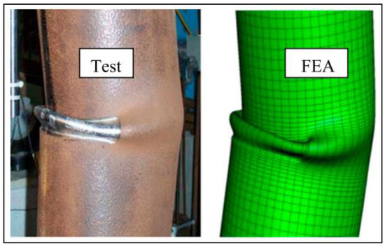
Figure 3.
Outward bulge buckling at the corrosion defect region [21].
Finally, since the pipe material was highly ductile, only wrinkling failure mode occurred, and none failed due to rupture. Similar buckling with wrinkling but without rupture behavior was also observed by Takahashi et al. [56], albeit without the influence of internal pressure. Takahashi et al. [56] noted that the buckling behavior for deep corrosion, = 0.8, was much more severe compared to those with medium depth corrosion, = 0.5. This was indicated by a much lower collapse moment for pipes with = 0.8 than those with = 0.5. In cases where the axial compressional load is significantly large, failure modes such as buckling and wrinkling may occur.
An FEA to assess the corrosion damage of pipelines subjected to combined internal pressure and external loading revealed that applying axial compressive stress and internal pressure caused buckling. This was prominent for pipes with shallow corrosion defects where the failure could be governed by global instability or buckling at the corrosion defect section of the pipe instead of rupture failure. The FEA model simulated API 5L X42 Grade B, X65, X80, and X100 pipelines subjected to defect depths ranging from 20% to 80% of the pipe wall thickness. Two sets of length and width dimensions were used, one being 8 by 2 with the other being 8 by 8. Referring to Figure 4, the pipes subjected to combined loads (internal pressure and axial compressive stress) above the failure locus were expected to fail via buckling, while those below were expected to remain safe [57].
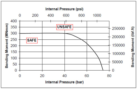
Figure 4.
In total, 457.2 mm (18 inch) Diameter Pipe with an 80% Deep Axial Groove—Internal Pressure versus Bending Moment Failure Locus [57].
A full-scale burst test on ASTM A333 Gr.6 pipeline material, which is commonly used as the secondary piping system of a nuclear power plant, showed that axial compressive forces subjected to corrosion defect region resulted in buckling failures [58]. The experiment included a four-point bending moment test that generated axial tensile and axial compressional forces. At the same time, the internal conditions of the pipeline were varied to be with or without internal pressure. Buckling failure can only occur before the onset of plastic deformation, and this behavior tends to happen with pipes with a relatively large diameter to full wall thickness ratio. Furthermore, the full-scale burst test proved that the length of corrosion defects, when subjected to external forces, influenced the failure mode. The pipe is prone to cracking failure with the increase in corrosion defect length and the decrease in internal pressure. However, an increase in the corrosion defect width decreased the susceptibility of cracking and shifted the failure behavior to ovalization. This trend can be conceptually visualized in Figure 5 [58]. This further proved that the corrosion defect length significantly affects the failure pressure of a pipe subjected to internal pressure and external loads.
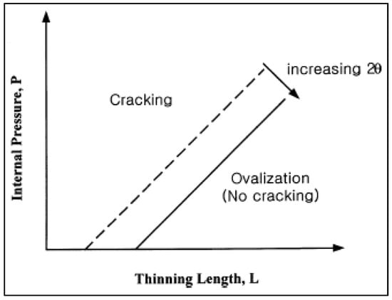
Figure 5.
A conceptual visualization of the effects of the axial length of the corrosion defect area and internal pressure on pipe on the crack occurrence in the corrosion defect area is shown. Note that symbolizes the width of the defect [58].
For compressional forces, the amount of pipe deformation depended on the corrosion defect’s length and width. The study also summarized that, for short axial defects, tensile stress is the dominant force for failure, while for extended defects, compressive stress becomes the dominant force for failure [58].
Roy et al. [31] investigated the possibility of bending collapse before any onset of rupture. Bending collapse is indicated by a zero slope of the moment versus the deflection curve. Bending collapse is due to a combination of progressive softening of the pipe wall through yielding, wrinkling, and ovalization. This softening behavior of the material is also supported by the work by Nicolella et al. [35], who found that it occurs when the maximum moment is achieved. Furthermore, it was found that bending collapse typically occurs when the pipe is subjected to relatively low internal pressure. However, it does happen when subjected to relatively high internal pressure, assuming sufficiently large axial compressive stress is imposed. Bjørnøy et al. [19] found that significantly large axial compressive stress resulted in buckling. An increase in corrosion defect width also results in a low maximum bending moment, while a decrease in corrosion defect width results in a steady increase in the maximum bending moment.
Kim and Park [58] examined the effect of the load-carrying capacity of pipelines with varying axial lengths subjected to external loads. Referring to Figure 6, the load-carrying capacity decreases as the corrosion defect length increases, regardless of the defect’s width. The reduction in carrying capacity is due to buckling instability that occurred with the increase in the longitudinal extent of defects [59].
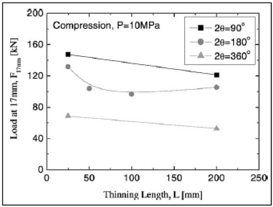
Figure 6.
Graph representing the varying axial defect length subjected to internal pressure and external forces and its effect on pipe load-carrying capacity [58].
Peng et al. [60] found that under pure tensile and compressional loads, circumferentially oriented defects showed stronger interacting behavior than axially oriented defects. Oh et al. [61] found that the axial extent of corrosion defects on plastic load limits is insignificant for pure bending forces (tension and compression).
Xu et al. [62] conducted an FEA to determine the effects of tensile and compressive strain on corrosion-affected pipelines. They found that a reduction in failure pressure occurred regardless of the presence of tensile or compressive strain. In addition, the failure pressure reduction increased as the tensile or compressive force intensity increased. Figure 7 shows that the plastic deformation distribution (region in red), when subject to external forces, is distinctly greater than when no external forces were subjected. Through the FEA stress-strain fields, it is evident that the plastic deformation regions grow in prominence with increasing tensile or compressive forces.
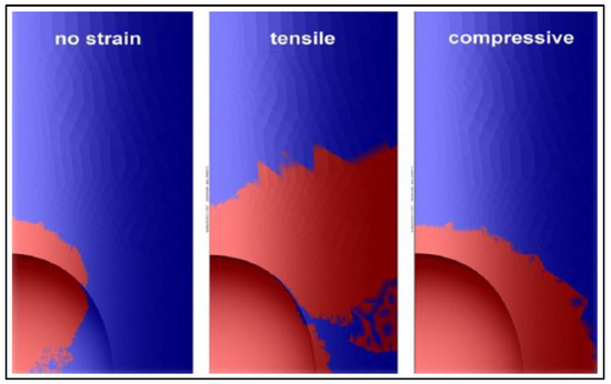
Figure 7.
Plastic deformation distribution on X80 grade steel pipe when subjected to no external strain (left), 0.2% tensile strain (middle), 0.2% compressive strain (right) [62].
The behavior of plastic deformation for tensile or compressive forces is distinct. This is because the stress-strain fields expand along the hoop direction for tensile forces, thus moving away from the defect. Meanwhile, the stress-strain fields expand by surrounding the defect for compressive forces. These differences in behavior result in differences in the failure mechanism. Defects subjected to tensile force are highly likely to undergo failure due to circumferential cracking. On the other hand, defects subjected to compressive forces are highly likely to undergo failure due to the buckling or wrinkling effect [62].
Xu et al. [62] also added that plastic failure due to external forces can be explained by the conversion of forces or energy. The application of external forces is usually converted to strain energy through lattice distortion, lattice movement, and many more. Since there is an increase in strain in the system, lower internal pressure is required to result in failure. In cases where corrosion defects are present, the plastic deformation region is significantly higher than that of an intact pipe. It is noteworthy that the presence of external forces often causes hardening behavior, which is supported by [62].
Yoosef-Ghodsi et al. [54] mentioned that another side effect of inward buckling is the ovalization of the pipe cross section. Excessive ovalization of a pipe prevents the passage of inspection devices such as a PIG through the pipeline. The maximum allowable ovalization recommended in the SUPERB project is 5% [63]. A study by Roy et al. [31] found that ovalization contributes to a loss of bending stiffness, which would eventually lead to bending collapse.
Vitali and Bruschi [30] found that failure modes such as bursting or fracture/plastic collapse would be dominant for pipes with a . This is because, for pipes with a , wrinkling only occurs at very high levels of pipe deformation. They added that bursting occurs when the pipe is subjected to axial compressive over-stress, resulting in excessive hoop strains, followed by external bulging accompanied by the thinning of the pipe and eventually bursting. Holh and Vogt [64] and Kirkwood et al. [65] mentioned that, in terms of the pipe material, the burst pressure of a new pipe is weakly dependent on the yield strength; however, it is strongly dependent on the ultimate tensile strength and the burst failure is dominant for thick-pressured pipes.
Roy et al. [31] conducted a full-scale test on X65 steel pipe with artificially machined corrosion subjected to internal pressure and axial compressive stress. Axial compressive stress resulted in pipe bending and rupturing at the nominal compression side. The rupture failure was found to have been initiated within the corrosion defect with cracks running along the axial direction. This is due to the maximum strain being located within the corrosion defect and the cracks initiating and propagating in the axial direction due to the local plastic hoop strain being much more significant than the tensile plastic strain at the corrosion defect. Further parametric studies using FEA found that several failures were due to local ruptures. The FEA is also consistent with the results of the full-scale test where the rupture would begin at the corrosion defect on the nominal compression side in the presence of bending stress. Furthermore, failure due to rupture occurs for serious corrosion defects when subjected to relatively high internal pressure and axial compressive stress.
It is generally known that an increase in the corrosion defect depth results in a significant decrease in the failure pressure. Similarly, for a pipe with constant corrosion depth, an increase in the corrosion defect length and width results in a lower failure pressure [31].
Bjørnøy et al. [66] conducted 12 full-scale burst tests to develop the DNV-RP-F101 corrosion assessment method. The full-scale burst tests were conducted on X52-grade pipes. Test 5, Test 6, Test 7, and Test 9 were subjected to combined internal pressure and axial compressive forces with longitudinally and circumferentially aligned corrosion defects, while Test 10, Test 11, and Test 12 were subjected to combined internal pressure and axial compressive forces with groove corrosion defects. The results revealed that under compressive stress, axially oriented corrosion defects have a lower failure pressure than pipes with circumferentially oriented corrosion defects, despite the circumferential corrosion encompassing the entire diameter of the pipe. An example of a burst failure of an axially oriented defect is shown in Figure 8. In total, two out of the three pipes that had circumferentially oriented corrosion defects failed in a manner that the rupture occurred along the longitudinal direction. This exact failure behavior was also noted by other researchers [41,67].
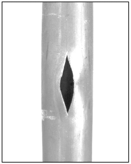
Figure 8.
Rupture failure of axially oriented corrosion defect [66].
In a few cases, as noted by Roy et al. [31], sufficient temperature increases, which results in high axial compressive stress, would cause the pipe to fail due to axial collapse. Axial collapse is the buckling of the pipe of a column specifically due to axial compressive stress. This type of buckling failure is often indicated by the zero slope of the axial load versus the midspan deflection curve.
In cases where the Bourdon effect due to internal pressure comes into account, specifically in pipe bends, the influence of axial compressive stress results in a significant change in the integrity of the pipe component [6]. As such, pipe bends are regarded as the weakest link in a piping system [68]. The significance of axial compressive stress on the failure pressure of a corroded pipe bend is high as it increases strain along the pipe wall [69]. A high concentration of stress and strain in the defect region drastically lowers the internal pressure required to cause the pipe bend to fail [70]. Despite this, only a limited amount of work has been conducted on the effects of axial compressive stress on the failure pressure of pipe bends.
Kim et al. [38] investigated the influence of a corrosion defect on the failure of a corroded pipe subjected to internal pressure and in-plane bending load, which incorporated axial compressive stress. This study was conducted using FEA, where the global deformation behavior of the pipe component was observed. It was found that axial compressive stress resulted in local buckling at the region of the defect, as illustrated in Figure 9 (red-colored region representing local buckling). It was emphasized that, generally, plastic instability is observed at locations of high deformations for the defects located at the extrados. However, in axial compressive stress, plastic instability was also observed in regions of lower deformations.
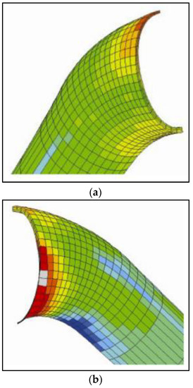
Figure 9.
Deformation of pipe bend with corrosion defect for opening bending moment at the (a) extrados and (b) intrados [38].
For defects located at the intrados, it was observed that the severity of the significance of the axial compressive stress on the failure of the pipe was higher than that of the tensile stress acting on the pipe (caused by ovalization). Overall, it was concluded that the incorporation of axial compressive stress into the analysis resulted in an exponential reduction in the failure pressure of the pipe bend, and that the effects of axial compressive stress are more significant compared to the tensile stress acting on the pipe.
4.2. Beneficial Effects
Chouchaoui and Pick [41,67] conducted comprehensive studies on corroded pipes and compared the effects of the close-ended conditions and open-ended conditions. The closed-ended condition is an application of longitudinal stress on the pipe due to hoop stress, while the open-ended condition takes into account the pure circumferential forces acting on the pipe without any longitudinal stress. Their results revealed that closed-ended conditions increase the failure pressure by delaying the plastic collapse of the corrosion defect region, providing slight support for the defect ligament through the surrounding material. Based on the von Mises stress analysis, it was revealed that for close-ended conditions, the biaxial stresses created more dilatational work in comparison to deviatoric stress. The biaxial stresses delayed the point for plastic collapse to occur. This, however, caused the close-ended conditions to undergo higher deformations than the open-ended conditions. Longitudinal compression caused by bending, on the other hand, caused a decrease in the failure pressure.
Research from Peng et al. [60] noted that for longitudinally oriented corrosion defects with shallow depths , the pure compressional force due to bending aided in increasing the load-carrying capacity for double defects that have a relative interacting spacing, , of greater than one. This trend is illustrated in Figure 10.
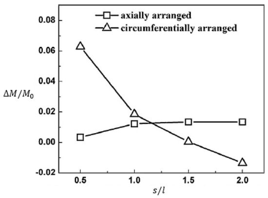
Figure 10.
Graph of bending limit load against the interacting distance of double defects for shallow defects [60]. Note: is the difference between the bending limit load of a pipe with single defect, , and the bending limit load of pipe with double defects, . Thus, a value of approaching 1 suggests an increasing interacting behaviour.
A study conducted by Kim et al. [38] on short lengths revealed that the load-carrying capacity of pipes due to compressional force was found to be higher in comparison to tensile force, which is consistent with research by Chouchaoui et al. [41,67].
5. Conclusions
When a corroded pipeline is subjected to internal pressure and axial compressive stress, the failure pressure is adversely affected, resulting in failure behaviors such as bending, buckling, wrinkling, ovalization, bursting/rupture, and axial collapse. Nevertheless, axial compressive stress on the corroded pipe may benefit the failure pressure as it provides slight support to the defect ligament through the surrounding material.
Most of the work reviewed only focused on single corrosion defects. It is recommended that future studies include the failure behavior of pipes with interacting corrosion defects subjected to both internal pressure and axial compressive stress. This is because interacting corrosion defects tend to result in lower failure pressure with complex failure behavior. In addition, future studies should also include failure behavior pipe bends with corrosion defects subjected to internal pressure and axial compressive stress, as they are the weakest link in a piping system.
6. Recommendations
Most research involving corrosion defects subjected to internal pressure and axial compressive stress focuses on single defects. However, it is known that interacting corrosion defects result in even lower failure pressure and complex failure behaviors. As such, more research must be conducted on pipelines with interacting corrosion defects subjected to internal pressure and axial compressive stress.
Furthermore, despite being the weakest link in a piping system, there is no corrosion assessment method for pipe bends subjected to internal pressure and axial compressive stress. The existing conventional pipe corrosion assessment codes, such as the DNV-RP-F101 and ASME-B31G, were developed for straight pipes with single and interacting corrosion defects. The difference in the stress distribution along the pipe walls causes a pipe bend to behave differently compared to a straight pipe. Hence, a reliable corrosion assessment method for corroded pipe bends with single and interacting defects subjected to internal pressure and axial compressive stress is needed.
In terms of full-scale burst tests, they should be conducted to determine which failure behavior is dominant. These full-scale burst test results could then be utilized to develop accurate finite element methods. Although finite element methods cost comparatively less and yield results faster, they must be verified against full-scale burst test results to ensure correct, consistent, and reliable results. The finite element method must consider proper boundary conditions, and sequence of load applications to accurately address the failure behavior. The material properties for the finite element method should also be prioritized, as most of the failure behavior would occur in the plastic range.
Funding
This work was supported by Yayasan Universiti Teknologi PETRONAS, Malaysia [015LC0-304 and 0153AA-E10].
Conflicts of Interest
The authors declare no conflict of interest.
Nomenclature
| Pipe diameter | |
| Corrosion defect depth | |
| Modulus of elasticity | |
| Force acting on the pipe component | |
| Total usage factor | |
| In-plane stress intensification factor | |
| Out-of-plane stress intensification factor | |
| Pipe length | |
| Pipe geometry factor | |
| Torsional moment | |
| Out-of-plane member bending moment | |
| Failure pressure of pipe | |
| Safe working pressure of the corroded pipe | |
| Internal pressure that results in yielding of a pristine pipe | |
| Length correction factor | |
| Bending stress | |
| Equivalent tensile stress | |
| Hoop stress due to fluid pressure | |
| Longitudinal stress in the pipe | |
| Standard deviation | |
| Fluid temperature | |
| Pipe thickness | |
| Section modulus of pipe | |
| Linear coefficient of thermal expansion | |
| Strain | |
| Factor for defining a fractile value for the corrosion depth | |
| Partial safety factor for corrosion depth | |
| Partial safety factor for longitudinal corrosion model prediction | |
| Poisson’s ratio | |
| Angular width of the defect | |
| Ultimate tensile strength pipe in the circumferential direction | |
| Load-line displacement | |
| Net free expansion | |
| Abbreviations | |
| ANN | Artificial neural network |
| BPNN | Back-propagation neural network |
| DNV | DNV-RP-F101 assessment code |
| FEA | Finite element analysis |
| FEM | Finite element method |
| HSS | High-strength steel |
| SVM | Support vector machine |
References
- Bhardwaj, U.; Teixeira, A.P.; Soares, C.G. Burst strength assessment of X100 to X120 ultra-high strength corroded pipes. Ocean Eng. 2021, 241, 110004. [Google Scholar] [CrossRef]
- Kumar, S.D.V.; Lo, M.; Karuppanan, S.; Ovinis, M. Failure Pressure Prediction of Medium to High Toughness Pipe with Circumferential Interacting Corrosion Defects Subjected to Combined Loadings Using Artificial Neural Network. Appl. Sci. 2022, 12, 4120. [Google Scholar] [CrossRef]
- Kumar, S.D.V.; Lo, M.; Arumugam, T.; Karuppanan, S. A review of finite element analysis and artificial neural networks as failure pressure prediction tools for corroded pipelines. Materials 2021, 14, 6135. [Google Scholar] [CrossRef]
- Lo, M.; Kumar, S.D.V.; Karuppanan, S.; Ovinis, M. An Artificial Neural Network-Based Equation for Predicting the Remaining Strength of Mid-to-High Strength Pipelines with a Single Corrosion Defect. Appl. Sci. 2022, 12, 1722. [Google Scholar] [CrossRef]
- Shuai, Y.; Zhou, D.-C.; Wang, X.-H.; Yin, H.-G.; Zhu, S.; Li, J.; Cheng, Y.F. Local buckling failure analysis of high strength pipelines containing a plain dent under bending moment. J. Nat. Gas Sci. Eng. 2019, 77, 103266. [Google Scholar] [CrossRef]
- Shuai, Y.; Zhang, X.; Huang, H.; Feng, C.; Cheng, Y.F. Development of an empirical model to predict the burst pressure of corroded elbows of pipelines by finite element modelling. Int. J. Press. Vessel. Pip. 2022, 195, 104602. [Google Scholar] [CrossRef]
- Zhang, Y.; Shuai, J.; Ren, W.; Lv, Z. Investigation of the tensile strain response of the girth weld of high-strength steel pipeline. J. Constr. Steel Res. 2021, 188, 107047. [Google Scholar] [CrossRef]
- Liu, X.; Xia, M.; Bolati, D.; Liu, J.; Zheng, Q.; Zhang, H. An ANN-based failure pressure prediction method for buried high-strength pipes with stray current corrosion defect. Energy Sci. Eng. 2020, 8, 248–259. [Google Scholar] [CrossRef]
- Kumar, S.D.V.; Karuppanan, S.; Ovinis, M. Artificial Neural Network-Based Failure Pressure Prediction of API 5L X80 Pipeline with Circumferentially Aligned Interacting Corrosion Defects Subjected to Combined Loadings. Materials 2022, 15, 2259. [Google Scholar] [CrossRef]
- Arumugam, T.; Karuppanan, S.; Ovinis, M. Finite element analyses of corroded pipeline with single defect subjected to internal pressure and axial compressive stress. Mar. Struct. 2020, 72, 102746. [Google Scholar] [CrossRef]
- Chin, K.T.; Arumugam, T.; Karuppanan, S.; Ovinis, M. Failure pressure prediction of pipeline with single corrosion defect using artificial neural network. Pipeline Sci. Technol. 2020, 4, 10–17. [Google Scholar] [CrossRef]
- Kumar, S.D.V.; Karuppanan, S.; Ovinis, M. Failure Pressure Prediction of High Toughness Pipeline with a Single Corrosion Defect Subjected to Combined Loadings Using Artificial Neural Network (ANN). Metals 2021, 11, 373. [Google Scholar] [CrossRef]
- Cosham, A.; Palmer, A.; Hopkins, P. The Assessment of Corrosion in Pipeline-Guidance in The Pipeline Defect Assessment Manual (PDAM). In Proceedings of the Pipeline Pigging and Integrity Management Conference, Amsterdam, The Netherlands, 17–18 May 2004; pp. 1–18. [Google Scholar]
- Belachew, C.T.; Ismail, M.C.; Karuppanan, S. Burst strength analysis of corroded pipelines by finite element method. J. Appl. Sci. 2011, 11, 1845–1850. [Google Scholar] [CrossRef]
- Schweitzer, P.A. Fundamentals of Corrosion: Mechanisms, Causes, and Preventative Methods; CRC Press: Boca Raton, FL, USA, 2009. [Google Scholar]
- Cosham, A.; Hopkins, P.; Macdonald, K.A. Best practice for the assessment of defects in pipelines—Corrosion. Eng. Fail. Anal. 2007, 14, 1245–1265. [Google Scholar] [CrossRef]
- De Andrade, E.Q.; Benjamin, A.C.; Machado, P.R.S.; Pereira, L.C.; Jacob, B.; Carneiro, E.G.; Guerreiro, J.N.C.; Silva, R.C.C.; Noronha, D.B. Finite element modeling of the failure behavior of pipelines containing interacting corrosion defects. In International Conference on Offshore Mechanics and Arctic Engineering—OMAE; ASME: New York, NY, USA, 2006; Volume 2006. [Google Scholar] [CrossRef]
- Bjørnøy, O.; Fu, B.; Sigurdsson, G.; Cramer, E.; Ritchie, D. Introduction and Background to DNV-RP-F101 Corroded Pipelines. In Proceedings of the Ninth International Offshore and Polar Engineering Conference, Brest, France, 30 May–4 June 1999. [Google Scholar]
- Peng, L.C. Stress analysis methods for underground pipelines. Pipe Line Ind. 1978, 47, 65–74. [Google Scholar]
- Soares, E.; Bruère, V.M.; Afonso, S.M.B.; Willmersdorf, R.B.; Lyra, P.R.M.; Bouchonneau, N. Structural integrity analysis of pipelines with interacting corrosion defects by multiphysics modelling. Eng. Fail. Anal. 2019, 97, 91–102. [Google Scholar] [CrossRef]
- Dewanbabee, H.; Das, S. Structural Behavior of Corroded Steel Pipes Subject to Axial Compression and Internal Pressure: Experimental Study. J. Struct. Eng. 2013, 139, 57–65. [Google Scholar] [CrossRef]
- Lee, E.; Audibert, J.; Hengesh, J.; Nyman, G. Landslide-Related Ruptures of the Camisea Pipeline System, Peru; Geological Society of London: London, UK, 2009; Volume 42, pp. 251–259. [Google Scholar]
- Chou, Z.; Cheng, J.; Zhou, J. Monitoring and prediction of pipe wrinkling using distributed strain sensors. In Proceedings of the 2006 International Pipeline Conference, Calgary, AB, Canada, 25–29 September 2006; pp. 307–315. [Google Scholar]
- Liu, B.; Liu, X.; Zhang, H. The Response of Buried Pipeli Ne Subjected to Landslides. In Proceedings of the Nineteenth International Offshore and Polar Engineering Conference, Osaka, Japan, 21–26 June 2009. [Google Scholar]
- Murray, S. Local buckling, strain localization, wrinkling and postbuckling response of line pipe. Eng. Struct. 1997, 19, 360–371. [Google Scholar] [CrossRef]
- Palmer, A.; Tebboth, L.; Miles, D.; Calladine, C. Instability of Pipelines on Slopes; ASME: New York, NY, USA, 1999. [Google Scholar]
- Oswell, J.; Hanna, A.; Doblanko, R.; Wilkie, S.J.O. Instrumentation yields geotechnical picture of slope movements along northern Canadian pipeline. Oils Gas J. 2001, 99, 62–67. [Google Scholar]
- Abdulhameed, D.; Adeeb, S.; Cheng, R.; Martens, M. The Influence of the Bourdon Effect on Pipe Elbow. In Proceedings of the 2016 International Pipeline Conference, Calgary, AB, Canada, 26–30 September 2016. [Google Scholar] [CrossRef]
- Abdulhameed, D.; Cheng, R.; Martens, M. The Influence of Bourdon Effect and Ovalization Effect on The Stress Distribution on Pipe Elbows. In Proceedings of the 2016 Pipeline Technology Conference, Calgary, AB, Canada, 25–27 September 2016; pp. 1–17. [Google Scholar]
- Vitali, L.; Bruschi, R.; Mork, K.J.; Levold, E.; Verley, R. Hotpipe project: Capacity of pipes subject to internal pressure, axial force and bending moment. In Proceedings of the Ninth International Offshore and Polar Engineering Conference, Brest, France, 30 May–4 June 1999. [Google Scholar]
- Roy, S.; Grigory, S.; Smith, M.; Kanninen, M.; Anderson, M. Numerical Simulations of Full-Scale Corroded Pipe Tests with Combined Loading; ASME: New York, NY, USA, 1997. [Google Scholar]
- Spangler, M.G.; Handy, R.L. Soil Engineering; HarperCollins: New York, NY, USA, 1982. [Google Scholar]
- Moser, A.P.; Folkman, S.L. Buried Pipe Design; McGraw-Hill: New York, NY, USA, 2001. [Google Scholar]
- Xu, L.; Lin, M. Analysis of buried pipelines subjected to reverse fault motion using the vector form intrinsic finite element method. J. Soil Dyn. Earthq. Eng. 2017, 93, 61–83. [Google Scholar] [CrossRef]
- Nicolella, D.P.; Smith, M.Q. Non-linear finite element prediction of wrinkling in corroded pipe. In Proceedings of the Seventh International Offshore and Polar Engineering Conference, Honolulu, HI, USA, 25–30 May 1997. [Google Scholar]
- Pipeline Report—P977H0024: Natural Gas Pipeline Rupture. 1997. Available online: https://www.tsb.gc.ca/eng/rapports-reports/pipeline (accessed on 29 December 2022).
- Guo, X.; Cao, Y.; Ma, H.; Xiao, C.; Wen, B. Dynamic analysis of an L-shaped liquid-filled pipe with interval uncertainty. Int. J. Mech. Sci. 2022, 217, 107040. [Google Scholar] [CrossRef]
- Kim, J.W.; Na, M.G.; Park, C.Y. Effect of local wall thinning on the collapse behavior of pipe elbows subjected to a combined internal pressure and in-plane bending load. Nucl. Eng. Des. 2008, 238, 1275–1285. [Google Scholar] [CrossRef]
- Wang, H.; Zhang, Z.; Qian, H.; Fan, F. Effect of local corrosion on the axial compression behavior of circular steel tubes. Eng. Struct. 2020, 224, 111205. [Google Scholar] [CrossRef]
- Chen, Y.F.; Zhang, J.; Zhang, H.; Liu, X.B.; Li, X.; Zhou, J.; Cao, J. Ultimate load capacity of offshore pipeline with arbitrary shape corrosion defects. China Ocean Eng. 2015, 29, 241–252. [Google Scholar] [CrossRef]
- Chouchaoui, B.; Pick, R. Behaviour of circumferentially aligned corrosion pits. Int. J. Press. Vessel. Pip. 1994, 57, 187–200. [Google Scholar] [CrossRef]
- Li, F.; Wang, W.; Xu, J.; Yi, J.; Wang, Q. Comparative study on vulnerability assessment for urban buried gas pipeline network based on SVM and ANN methods. Process Saf. Environ. Prot. 2019, 122, 23–32. [Google Scholar] [CrossRef]
- Kumar, S.D.V.; Lo, M.; Karuppanan, S.; Ovinis, M. Empirical Failure Pressure Prediction Equations for Pipelines with Longitudinal Interacting Corrosion Defects Based on Artificial Neural Network. J. Mar. Sci. Eng. 2022, 10, 764. [Google Scholar] [CrossRef]
- Kumar, S.D.V.; Karuppanan, S.; Ovinis, M. An empirical equation for failure pressure prediction of high toughness pipeline with interacting corrosion defects subjected to combined loadings based on artificial neural network. Mathematics 2021, 9, 2582. [Google Scholar] [CrossRef]
- Tohidi, S.; Sharifi, Y.; Shari, Y. Thin-Walled Structures Load-carrying capacity of locally corroded steel plate girder ends using artificial neural network. Thin-Walled Struct. 2016, 100, 48–61. [Google Scholar] [CrossRef]
- Netto, T.; Ferraz, U.; Estefen, S. The effect of corrosion defects on the burst pressure of pipelines. J. Constr. Steel Res. 2005, 61, 1185–1204. [Google Scholar] [CrossRef]
- Timoshenko, S.P.; Gere, J.M. Theory of Elastic Stability; Courier Corporation: Chelmsford, MA, USA, 2009. [Google Scholar]
- Bai, Y.; Hauch, S.; Jensen, J.C. Local buckling and plastic collapse of corroded pipes with yield anisotropy. In Proceedings of the Ninth International Offshore and Polar Engineering Conference, Brest, France, 30 May–4 June 1999. [Google Scholar]
- Smith, M.Q.; Nicolella, D.P.; Waldhart, C.J. Full-scale wrinkling tests and analyses of large diameter corroded pipes. In Proceedings of the 2nd International Pipeline Conference, Calgary, AB, Canada, 7–11 June 1998; pp. 543–551. [Google Scholar]
- Gurney, K. An Introduction to Neural Networks; UCL Press: London, UK, 1997. [Google Scholar]
- Lo, M.; Karuppanan, S.; Ovinis, M. Failure Pressure Prediction of a Corroded Pipeline with Longitudinally Interacting Corrosion Defects Subjected to Combined Loadings Using FEM and ANN. J. Mater. Sci. Eng. 2021, 9, 281. [Google Scholar] [CrossRef]
- Dewanbabee, H. Behaviour of Corroded X46 Steel Pipe under Internal Pressure and Axial Load; University of Windsor: Windsor, ON, Canada, 2009; pp. 1–274. [Google Scholar]
- BjØrnoy, O.; Sigurdsson, G.; Marley, M. Background and Development of DNV-RP-F101 Corroded Pipelines. In Proceedings of the Eleventh International Offshore and Polar Engineering Conference, Stavanger, Norway, 17–22 June 2001. [Google Scholar]
- Yoosef-Ghodsi, N. Behavior of Girth-Welded Line Pipe; University of Alberta: Edmonton, AT, Canada, 1995. [Google Scholar]
- Smith, M.Q.; Grigory, S.C. New procedures for the residual strength assessment of corroded pipe subjected to combined loads. In Proceedings of the 1st International Pipeline Conference, Calgary, AB, Canada, 7–11 June 1996; pp. 387–400. [Google Scholar]
- Takahashi, K.; Ando, K.; Hisatsune, M.; Hasegawa, K. Failure behavior of carbon steel pipe with local wall thinning near orifice. Nucl. Eng. Des. 2007, 237, 335–341. [Google Scholar] [CrossRef]
- Chauhan, V.; Swankie, T.D.; Espiner, R.; Wood, I. Developments in Methods for Assessing the Remaining Strength of Corroded Pipelines. In Proceedings of the NACE Corrosion 2009 Conference Expo, Houston, TX, USA, 22–26 March 2009; pp. 1–29. [Google Scholar]
- Kim, J.W.; Park, C.Y. Effect of length of thinning area on the failure behavior of carbon steel pipe containing a defect of wall thinning. Nucl. Eng. Des. 2003, 220, 274–284. [Google Scholar] [CrossRef]
- Blake, A.C. 20, Uniform Cantilever Beams. In Practical Stress Analysis in Engineering Design; CRC Press: New York, NY, USA, 1990; pp. 211–222. ISBN 082478152X. [Google Scholar]
- Peng, J.; Zhou, C.; Xue, J.; Dai, Q.; He, X. Safety assessment of pipes with multiple local wall thinning defects under pressure and bending moment. Nucl. Eng. Des. 2011, 241, 2758–2765. [Google Scholar]
- Oh, C.; Kim, Y.; Park, C. Effects of local wall thinning on net-section limit loads for pipes under combined pressure and bending. Nucl. Eng. Des. 2009, 239, 261–273. [Google Scholar] [CrossRef]
- LXu, Y.; Cheng, Y.F. Reliability and failure pressure prediction of various grades of pipeline steel in the presence of corrosion defects and pre-strain. Int. J. Press. Vessel. Pip. 2012, 89, 75–84. [Google Scholar] [CrossRef]
- Bjørnsen, T.; Hagen, Ø.; Mørk, K.J. Reliability Based Pipeline Design And Integrity Assessment: Pipeline Industry On the Verge. In Proceedings of the Fifth International Offshore and Polar Engineering Conference, The Hague, The Netherlands, 11–16 June 1995. [Google Scholar]
- Hohl, G.; Vogt, I. Allowable strains for high strength linepipe. 3 R Int. 1992, 31, 696. [Google Scholar]
- Kirkwood, M.; Fu, B.; Vu, D.; Batte, A. Assessing the Integrity of Corroded Linepipe-An Industry Initiative. In Aspect’96: Advances in Subsea Pipeline Engineering and Technology; OnePetro: Richardson, TX, USA, 1996. [Google Scholar]
- Bjørnøy, O.H.; Sigurdsson, G.; Cramer, E. Residual Strength of Corroded Pipelines, DNV Test Results. In Proceedings of the Tenth (2000) International Offshore and Polar Engineering Conference, Seattle, WA, USA, 28 May–2 June 2000; Volume II, pp. 1–7. [Google Scholar]
- Chouchaoui, B.A.; Pick, R.J. Behaviour of longitudinally aligned corrosion pits. Int. J. Press. Vessel. Pip. 1996, 67, 17–35. [Google Scholar] [CrossRef]
- Shuai, Y.; Shuai, J.; Xu, K. Probabilistic analysis of corroded pipelines based on a new failure pressure model. Eng. Fail. Anal. 2017, 81, 216–233. [Google Scholar] [CrossRef]
- Mokhtari, M.; Melchers, R.E. A new approach to assess the remaining strength of corroded steel pipes. Eng. Fail. Anal. 2018, 93, 144–156. [Google Scholar] [CrossRef]
- Shuai, Y.; Shuai, J.; Liu, C. Research on the reliability methods of corroded pipeline. Pet. Sci. Bull. 2017, 2, 288–297. [Google Scholar]
Disclaimer/Publisher’s Note: The statements, opinions and data contained in all publications are solely those of the individual author(s) and contributor(s) and not of MDPI and/or the editor(s). MDPI and/or the editor(s) disclaim responsibility for any injury to people or property resulting from any ideas, methods, instructions or products referred to in the content. |
© 2023 by the authors. Licensee MDPI, Basel, Switzerland. This article is an open access article distributed under the terms and conditions of the Creative Commons Attribution (CC BY) license (https://creativecommons.org/licenses/by/4.0/).