Abstract
The combination of pavement rutting, poor road alignment, and extreme adverse weather will seriously threaten the driving safety of vehicles, whereas only a few of these factors are commonly concerned. This study aims to efficiently evaluate the impacts of various driving conditions on the lateral stability of the vehicle and produce a practical recommendation for pavement maintenance in what concerns rutting. A systematic framework was, thus, developed to conduct a comprehensive evaluation of the lateral stability of the vehicle, which incorporates a single-factor test and multi-factor test based on the stability indicators obtained from Carsim simulations. The vehicle road weather model was established in the Carsim software by considering seven factors, including driving speed, width–height ratio (WHR) of rutting sidewall, radius of circular curve, superelevation, crosswind angle, crosswind speed, and friction coefficient, respectively. The results show that the established framework behaves with satisfactory performance, regarding evaluating the effect of various impact factors on the lateral stability of the vehicle while driving across rutting. Stability indicators suddenly fluctuate in a short time, due to the instantaneous wandering behavior of crossing rutting. Additionally, the sudden fluctuation phenomenon is greatly enlarged, and the vehicle is inclined to occur with lateral instability when WHR equals 5, particularly in roll-over instability. It is recommended to concurrently confine the WHR greater than 10 and friction coefficient greater than 0.4, in order to ensuring driving stability. The multi-factor test revealed that the vehicle speed and WHR of the rutting are leading factors that affect driving stability, followed by the radius of circular curve, superelevation, crosswind angle, crosswind speed and friction coefficient, respectively, which are both essential factors for driving stability. The outcomes of this study may contribute to supplying guidelines for controlling key adverse conditions and making decisions on pavement maintenance.
1. Introduction
Rutting is a common distress of asphalt pavements, which adversely impacts the serviceability of the pavement and driving stability of the vehicle [1,2]. When a vehicle drives through a rut, it will produce a phenomenon known as wandering, and the vehicle may show potentially unstable, oscillatory lateral, or yaw motions with a low frequency. Drivers may feel discomfort, due to bumps, while negotiating the rutting or even cause serious traffic accidents due to operational faults. The number of accidents per 100 million vehicle-miles of highways in the states of Arizona, North Carolina, and Maryland significantly increases when the rut depth approaches 10 mm [3]. It has been identified that the presence of rutting would cause lateral instability in vehicles and impact driving safety when the rutting depth exceeds 20 mm [4]. So, driving safety is remarkably influenced by pavement rutting.
Exactly as the findings about the threats of rutting to driving safety, rutting distress is more crucial for influencing driving safety than roughness or cracking, due to the large height differences and features of easy ponding and frozen in rutting. In order to improve the rutting maintenance from the perspective of driving safety, quite a few investigators have studied the effects of different rutting shape indicators on driving comfort or the safety of vehicles and obtained their allowable values. Zheng et al. [5] possessed the view that the rut depth and rut side angle obviously affected the maximum vertical acceleration of the vehicle, while the rut average width had small effects. A mathematical model regarding the interaction between automobiles, wheels, and road surfaces with ruts was developed by Vansauskas et al. [6]. They found that the vehicle became unstable if the rut is over 5cm and the width over 50 cm, when driving at a speed of 60 km/h. Guo et al. [7] suggested lateral offset and lateral acceleration as rutting indicators for evaluating the influence of rutting length. Jia et al. [8] found that driving across rutting had a greater influence than driving on the rutting sidewall and stated that rutting depth should be less than 20 mm to ensure driving quality when across a rut on dry pavement. Kuznetsov et al. [9] determined the maximum allowable rutting depth via a computer program and accordingly defined 14 mm as the allowable value of rutting depth to ensure safety when driving over 160 km/h.
In recent years, in addition to the road safety affected by pavement rutting, unfavorable conditions with adverse weather have been frequent events and constantly cause serious impacts on traffic safety. Approximately 300 traffic accidents happened due to adverse weather in Germany in January 2016 [10]. More than 60% of traffic accidents caused by fierce winds and other adverse weather were accounted for in the south-eastern coast of China [11]. Adverse weather mainly includes strong winds, heavy rain, ice, and snow [12], and even their simultaneous occurrence. On the one hand, the influence of adverse weather can be considered as a kind of action subject to the vehicle and, thus, affecting its driving stability. On the other hand, the driving risk possibly intensifies, due to the coupling effect of adverse weather and rutting distress. The ponding formed in the rutting under adverse weather may decrease the friction coefficient of road surface and change the mechanical characteristics of the vehicle, resulting in losing lateral stability [13], while driving in heavy rains, snows, and strong winds. Moreover, a water film on the pavement surface will generate a hydroplaning phenomenon on the rolling tire, as a result of the joint impact of rutting and ponding. Due to the hydroplaning phenomenon, the water pressure in the front of the tire pushes the water under the tire, and then the water film is formed and separates the tire from the pavement, thus resulting in a loss of road friction coefficient [14,15]. Confronting such adverse circumstances, smart tires, a promising technology, are highlighted in detecting distressed rutting sections and road friction, then interacting with follow-up vehicles to avoid unfavorable positions, in order to ensure driving stability [14,16].
In addition to adverse weather, traffic accidents more frequently happen in horizontal curve segments than tangent segments of the road [17,18]. Fatal accidents commonly suddenly occur due to loss of lateral sideslip stability or roll-over stability as a result of unfavorable external factors. Exceeding the limit value of side friction is a key reason for lateral instability in curve segment [19,20], but it connects closer relationship with weather and pavement material. The instability of the vehicle is generally induced by inappropriate geometry parameters of curve segments. The relevant studies have demonstrated that the accident frequency dramatically increases as the radius of the curve decreases [21]. In addition, the vehicle on the curve segment is prone to occur kidding and roll-over with the increase of road slope and the decrease of superelevation [22]. However, the sideslip risk is not remarkably affected by superelevation of the road [23]. As a result, driving stability analysis is a complex and comprehensive topic, which shall follow the integrated consideration of adverse weather, road, alignment, and rutting in need.
As a result, recent studies have highlighted the significance of researching driving stability under adverse weather, as well as focusing on adverse effects caused by alignment of curve segment. It is generally accepted that strong winds and heavy rains lead to low lateral stability [24,25,26,27], which is susceptible to resulting in sideslip, yawing, and roll-over instability. The evaluations of these instabilities under unfavorable situations were performed by means of analyzing the dynamic indicators of vehicles [28], including lateral displacement, lateral acceleration, load transfer rate, yaw angle rate, and roll-over angle [29,30,31,32,33,34]. Chen et al. [35,36] found that the car is more likely to sideslip and the cargo truck has higher roll-over risks under crosswind. Wang et al. [37] simulated driving experiments under snowy weather in a bridge and tunnel connection segment, and finally found that the large lateral offset can be prevented by increasing the friction coefficient of pavement and radius of circular curve. Yin et al. [38] investigated the skidding, roll-over, and lateral slip of the vehicle by accounting radius of circular curve and superelevation and found that the safety margin of the vehicle’s skidding, roll-over, and lateral slip increased when the radius of the circular curve and superelevation increases. Alrejjal et al. [39] focused on the roll-over propensity influenced by horizontal and vertical alignments under different weather conditions, thus revealing that the lateral acceleration was amplified due to a tight degree of curvature and steep downgrades.
The previous findings mainly investigated the effect of single adverse weather or road alignment on driving stability, but neglected rutting conditions accordingly, or solely analyzed the unfavorable conditions of vehicle stability due to rutting distress, with only a few research on the composite effects of rutting and wet condition. However, the dynamic response process of the vehicle driving across rutting coupled in curve segments with adverse weather is a crucial issue that determines driving safety. So, relevant evaluation remains to be proposed, so as to implement the management and control of adverse situations, as well as make pavement maintenance decisions.
Given the research shortcomings and gaps above, this study intends to figure out the dynamic responses of the vehicle driving across rutting on the curve segment under adverse weather and further evaluate the effects of various driving conditions on the lateral stability of the vehicle. So, a framework for evaluating lateral stability of the vehicle was developed to efficiently describe the impacts of different factors. The Carsim software was utilized to simulate the process of driving across rutting, considering various road alignments and adverse weather. The vehicle’s dynamic responses that represent lateral stability were analyzed via indicator lateral acceleration (LA), slip angle (SA), load transfer ratio (LTR), and roll-over angle (RA). Considering the likelihood of poor correlation between LA, SA, LTR, and RA, the integrated lateral stability caused by various factors was compared with entropy-weighted grey relational analysis (GRA), based on orthogonal tests. The outcomes of this study will contribute to establishing criteria for controlling key adverse conditions and making decisions on pavement maintenance.
2. A Systematic Framework for Evaluating Lateral Stability of the Vehicle under Various Driving Conditions
Pavement rutting, road alignment, adverse weather, and vehicle speed are significant factors that potentially influence the driving stability of the vehicle. However, the combined effects may be neglected, due to incomplete consideration [40]. Therefore, the framework for evaluating the lateral stability of the vehicle was developed to efficiently describe the impacts of different factors. Figure 1 is the technical framework for evaluating the lateral stability of the vehicle under various driving conditions. Four indicators that separately represent sideslip stability and roll-over stability were output to preliminary evaluate the lateral stability of the vehicle. Single-factor analysis was first conducted by controlling the constant single factor. After that, the correlations of LA, SA, LTR, and RA were examined through Pearson’s correlation coefficient to validate their consistency in evaluating lateral stability of the vehicle. GRA and the entropy weight method were applied to derive comprehensive relation grade (CRG) based on an orthogonal test, in which multi-factor analysis was performed, thus evaluating the lateral stability of the vehicle. The details about the developed framework are described in the following parts.
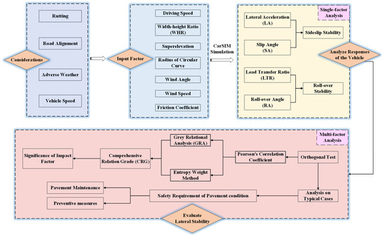
Figure 1.
Technical framework of this study.
2.1. Factors in Consideration
As stated before, the combined factors of pavement rutting, road alignment, and adverse weather denote various driving conditions, which may cause unacceptable vehicle instability. In order to figure out the effects of various driving conditions on the lateral stability of the vehicle, totally, seven factors are taken into consideration, including the driving speed (Vc), width–height ratio (WHR) of rutting sidewall, radius of circular curve (R), superelevation (e), lateral wind angle (δlw), wind speed (Vlw), and friction coefficient (f). Vc is on behalf of the driving condition. Factor f mainly relates to rainy and snowy weather. δlw and Vlw indicate lateral wind action. R and e are parameters of road alignment. WHR characterizes the effect of rutting distress.
2.2. Evaluation Indicators of Lateral Stability
2.2.1. Sideslip Stability
Vehicles will be subjected to lateral force when driving on curve segments, especially in adverse weather with wind and rain. If the vehicle drives through the curve at a pretty high speed, the grip of the wheels may dramatically decrease, thus resulting in the drift of the vehicle and large lateral sideslip [23,41]. Figure 2 shows the vertical view of a dynamic model, while the vehicle drives on curve segments. Fsyl and Fsyr denote lateral forces exerted on the left and right tires of s th axle (s = 1, 2). Vw1, Vw2, Vw3, and Vw4 are the velocities of four wheels, respectively. Vvb is the forward velocity of the vehicle body. α1, α2, α3, and α4 denote the slip angles of front and rear wheels, which are defined as angles between Vwi (i =1, 2, 3, 4) and wheel direction, respectively. β denotes the slip angle of vehicle body, which is defined as the angle between Vvb and longitudinal axis. δs is the steering angle of the front wheel.
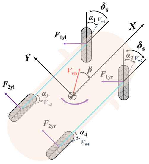
Figure 2.
Vertical view of vehicle model on curve segments.
In addition, the superposition of lateral force caused by lateral wind and the centrifugal effect will significantly increase the lateral acceleration (LA), resulting in the vehicle laterally deviating from the original trajectory and increasing sideslip risks. It was specified that the LA for ordinary cars shall be less than 0.4 g.
Slip angle (SA) of the vehicle body is the angle its velocity vector at the center of gravity makes with the longitudinal axis (X axis) of the vehicle, which is also used to characterize the risk of side slip, as described by [42]:
where vy and vx denote the lateral and longitudinal velocity of vehicle body, respectively. The safety threshold for slip angle is 5° [43].
2.2.2. Roll-Over Stability
Vehicle roll-over has been acknowledged as a serious vehicle accident with the highest fatality [44]. The vehicle perhaps rolls over as a result of large rotating degrees, due to an unstable mechanical state caused by cross slope of road or other external factors. Figure 3 presents the front view of vehicle model on curve segments with cross slope θ. The perpendicular forces and tangent forces exerted on the tires are FZL, FZR, FYL, and FYR. m is sprung mass, and g and ay denote gravitational acceleration and lateral acceleration. The ϕ is the roll-over angle of the car. It is clearly illustrated that the forces of the car on the curve segments differ from that of the tangent segments.
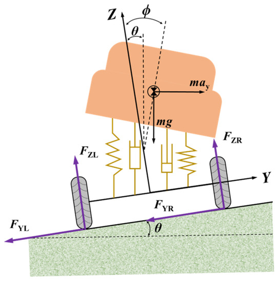
Figure 3.
Front view of vehicle model on curve segments.
Load transfer ratio (LTR) was selected to characterize the roll-over stability of a car, which is defined as the ratio of the load transferred from the inside wheels to the outside wheels to the total load of the vehicle during travel [45], as given by:
where LTR(t) denotes load transfer ratio at time t, and FZR(t)s and FZL(t)s are the vertical forces acting on the outer and inner tires of the s-th axle at time t, respectively. When the vehicle is driving in a stable state, the forces on the left and right tires are equal, that is, LTR = 0. When the inner wheel is off the ground, all the loads are transferred to the outer wheels, that is, LTR = 1. In this case, the vehicle is traveling in a limit state of roll-over instability. In general, the vehicle has a certain risk of roll-over when 0.6 ≤ LTR < 0.8 and is vulnerable to roll-over when 0.8 ≤ LTR < 1 [46,47].
As shown in Figure 3, ϕ is the roll-over angle. The vehicle will lean laterally, while turning or encountering impact, so the vehicle may roll over if the roll-over angle (RA) is too large. It is generally accepted that the assessment of RA should be carried out in conjunction with LA and concurrently not exceed the maximum value of 6°. Combining the characteristics of LA in this study, the safety threshold for RA is considered to be 6°.
2.3. Single-Factor Test Design
In order to figure out how vehicle stability varies with a single factor, a single-factor test was conducted by controlling for the single factor being constant and changing other factors. Simulation schemes are shown in Table 1. The vehicle was set to run at a high speed ranging from 90 km/h to 120 km/h, according to the common operating speeds of passenger cars in China expressways and design speed specified in Chinese Standard JTG D20-2017 [48]. This would contribute to an understanding, regarding safe operating speeds and whether the existing speed limit has to be updated in order to avoid dangerous circumstances. The wind speeds were selected according to class 7 to class 9 wind and values from previous studies, because these may affect the lateral stability of the vehicle [11,49]. The friction coefficient was determined based on the wet conditions of the road surface, as introduced in Section 3.2. By conducting designed simulations, the indicator-time curve was determined to analyze the vehicle’s responses under various driving conditions.

Table 1.
Simulation schemes design of single-factor analysis.
2.4. Multi-Factor Test Design
2.4.1. Orthogonal Test
The previous section is about the design of simulation schemes with the purpose of studying every single factor. However, driving safety is significantly influenced by extreme conditions where multiple factors are applied. So, an orthogonal test was conducted in this section. Seven factors were still investigated, consistent with the above section, including Vc, WHR, R, e, δlw, Vlw, and f, representing vehicle velocity, WHR of rutting, the radius of circular curve, superelevation, lateral wind angle, lateral wind speed, and friction coefficient, respectively. Four levels of each factor were designed to represent the degree that is unfavorable to driving safety. Interactions between various factors were ignored, and the simulation schemes and results are shown in Table 2.
Table 2.
Orthogonal test design.
2.4.2. Evaluation Method
- Pearson’s Correlation Coefficient
As mentioned above, LA, SA, LTR, and RA were generally utilized to evaluate the lateral stability of the vehicle. However, the results determined from these four indicators may show diverse states of stability. So, the Pearson’s correlation analysis was conducted to examine the consistency in evaluating the sideslip stability and roll-over stability of the vehicle. The calculation of Pearson’s correlation rxy was expressed as:
where x and y denote any two of LA, SA, LTR, and RA. cov(x, y) is the covariance of x and y. var(x) and var(y) are the variances of x and y, respectively.
- Grey Relational Analysis (GRA)
Grey relational analysis (GRA) is generally used to evaluate the correlation between factors in multi-factor systems. In this section, grey relational coefficient (GRC) and grey relational grade (GRG) are adopted to characterize the correlation between the testing factors and targeted indicators LA, SA, LTR, and RA. The basic process for grey relational analysis mainly includes the following four steps [50].
- (1)
- Confirmation of reference sequence and comparison sequence
As expressed in the Equations below, four indicators, i.e., LA, SA, LTR, and RA, were taken as reference sequences, respectively. The comparison sequence was composed of above seven factors.
where denotes targeted output (LA, SA, LTR, and RA) at case i in Table 2 (i = 1,2,3,…, 32), and denotes inputting factors (Vc, WHR, R, e, δlw, Vlw, and f), k = 1,2,3,4,5,6,7.
- (2)
- Normalization of the original test data
The units and orders of magnitude for seven factors are different, so they need to be compared in the same range. Therefore, the original test data were processed by normalization. The calculation processes were expressed as Equations (6) and (7).
where denotes normalized value of LA, SA, LTR, and RA at case i, and denotes normalized value at case i of experimental factor k. and denote the maximum and minimum value of targeted output. and denote the maximum and minimum vale of inputting factor k.
- (3)
- Calculation of the proximity
The proximity matrix can be obtained through calculation absolute value of the difference of and , as expressed in Equation (8).
where denotes the absolute value of the difference of and .
- (4)
- Calculation of GRC and GRG
GRC is calculated as Equation (9).
And GRG is express as:
where denotes grey relational coefficient (GRC), and denote minimum and maximum of the absolute value of , respectively. ρ represents distinguishing coefficient, which usually takes 0.5. denotes grey relational grade (GRG), and m is the number of experiment case (equal to 32).
- Comprehensive Relation Grade (CRG)
LA, SA, LTR, and RA were regarded as targeted indicators to characterize the lateral stability of the vehicle. However, these indicators varied in unit concurrently with a difference in evaluating instability mode (sideslip and roll-over). So, a comprehensive indicator that indicates the effect of seven factors on driving stability should be proposed. In this section, a comprehensive relation grade (CRG) is proposed based on the entropy weight method and grey relational analysis.
The entropy weight method was used to calculate the weight of each indicator (LA, SA, LTR, and RA). An initial matrix A formed by four indicators from case 1 to case 32 was constructed as follows. The corner mark j = 1, 2, 3, 4, which represents LA, SA, LTR, and RA, respectively.
Then, the removal of the indicator dimension was conducted by normalization, as given by:
Entropy value of j th indicator as calculated as:
Entropy weight of j th indicator was calculated as [51]:
Finally, the targeted comprehensive relation grade (CRG) was calculated as:
3. Simulation Model
3.1. Modelling Vehicle
In this section, a simulation model was established with the Carsim software. It was generally agreed that the types of vehicles involved in accidents were mainly small vehicles (cars, minibuses) [52]. Since small-size passenger cars generally have a faster-running speeds, compared with SUVs or large trucks, the driving safety affected by rutting and adverse conditions is worth considering indeed. So, a small-size E-class vehicle was selected in the datasets provided by Carsim and modified manually based on actual vehicle parameters [37], as shown in Figure 4. The main parameters are shown in Table 3. The aerodynamics coefficients were the functions of aerodynamic slip angle, which were selected as default values in Carsim.
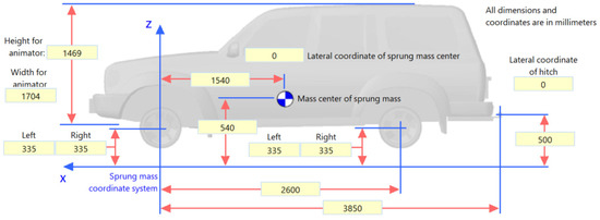
Figure 4.
Vehicle parameters setting.
Table 3.
Main parameters of vehicle model.
3.2. Modelling Adverse Weather
The safety of automobile driving is significantly influenced by adverse weather. The ponding caused by strong rainfall on the pavement may induce the hydroplaning potential, thus resulting in an obvious reduction of the friction coefficient of pavements [15,53]. The variation of real road friction due to hydroplaning is not only related to the depth of water accumulation and driving speed [15,54], but also concerned with factors such as the tire properties and pavement surface properties [55], which is a comprehensive research issue. Additionally, it will become worse if the impact of side wind on the lateral stability of automobiles is considered, which may form the combined effect of rainfall, ice, and crosswind, thereby greatly increasing the complexity of the loading characteristics of automobiles and the possibility of safety accidents. Additionally, the present study focuses on the analysis of different factors affecting vehicle stability, so the impact of hydroplaning phenomenon under a rain scenario is simplified by reducing the friction coefficient. As a result, regarding the effects of rain, ice, and snow on road surface conditions, they generally increase the driving risks by decreasing the friction coefficient between the pavement surface and tire. So, different friction coefficients were input to indicate adverse weather, according to findings in [13], as given in Table 4.
Table 4.
Moisture conditions of pavement under different weather conditions.
In terms of modeling wind velocity and wind direction in CarSim aerodynamics, the linear interpolation and extrapolation function was used to model wind velocity and wind angle. Wind velocity is defined as zero in 0–2 s, increases linearly to the target speed in 2–4 s, maintains a constant wind speed, starts to decrease linearly at 23 s, and decreases to 0 at 25 s. Additionally, the wind angle is set as consistent with wind speed.
3.3. Modelling Road
Road conditions highly determine vehicle stability, which connects to its interaction with the wheel [56]. In terms of modeling the road, it mainly comprises a radius of circular curve, superelevation, and rutting. A set of horizontal curves with different values of radius were established, in order to test vehicle stability on curve segments, with a total length of 1200 m. Superelevation was set in the form of a lateral pavement gradient.
Concerning modeling pavement rutting, the selection of rutting parameters is of particular importance. When a vehicle drives parallel to the rutting direction, minor effects on driving safety may occur. However, in the case of changing lanes or directions, a vehicle directly drives across a rut, thereby wandering behavior occurs [57], in which the vehicle may show unstable, lateral, or yaw motions, as if the vehicle went through a hole.
As presented in Figure 5, h denotes the rutting depth, and w is the rutting width. The rutting shape is commonly described with trigonometric functions [58], as given by Equation (16). The inclination angle of the tire is expressed as Equation (17).
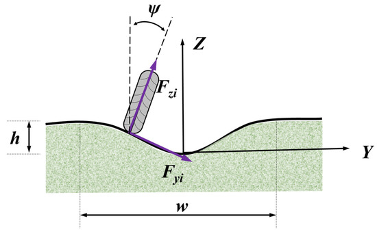
Figure 5.
Diagram of the wheel driving across a rut.
Though conjoint force analysis with a rut, the equation of vehicle motion is given by:
where denotes the cornering stiffness of the tire, denotes the camber stiffness of the tire, is the vertical force exerted at tire, m equals tire mass, and is the driving speed along x axis. Equation (18) presents free vibration equation with damping when the tire negotiates a rut. It can be found that the damping coefficient is proportional to , but inversely proportional to . Additionally, stiffness is obviously decided by rutting depth and rutting width. So, a higher driving speed will lead to a large vibration frequency while crossing a rut. Meanwhile, the rutting dimension has an impact on the vibration properties of the vehicle.
The lateral vehicle dynamics when instantaneously crossing a rut are rather complex, not only for a single tire or a single axle, but also for the whole vehicle. So, evaluating the dynamic condition of the vehicle considering rutting is more crucial than roughness, cracking, and other pavement distresses. Further, from the equation of vehicle motion (18), it implies that the rutting depth and rutting width show strong connection with the dynamic vibration properties of the vehicle.
The three main parameters of rutting are generally used to characterize driving safety. Normally, the maximum rutting depth (RD) is used to evaluate the rutting conditions, which affects the driving safety by the pattern of height difference and fluctuation. The rutting width (RW) is also an important parameter to characterize the rutting shapes. When the ruts are narrow, the wheels experience large changes in elevation in a very short period of time, and the vehicle’s recovery adaptations are unable to quickly follow the changes, making it inclined to lose stability. A smaller RW will present a greater impact on the driving stability. The width–height ratio (WHR) of the rutting sidewall denotes the dip angle of rutting sidewall, which refers to the ratio of the width-to-height of the rut sidewall. A higher WHR indicates a greater resistance to be overcome when changing the trajectory of the vehicle, and the greater the resistance to steering that the vehicle will experience. Therefore, in order to excellently characterize the effects of height fluctuation and lateral crossing when driving across rutting, WHR is selected as a factor that influences driving stability in different simulation cases.
In terms of modeling pavement rutting, the cross-sectional rutting shape was regularly simplified as a trapezoid because actual irregular shapes of the rutting were hard to directly describe [2,59], as shown in Figure 6a. It has been demonstrated that the WHR of the rutting sidewall had a greater impact on the lateral stability of the vehicle, compared with the rutting depth and rutting width, when it comes to discussing the case of vehicles negotiating the rutting sidewall [5,8]. Therefore, different WHRs (20, 15, 10, 5) were imported in Carsim software, which correspond to different heights of the rut sidewall (10 mm, 13.33 mm, 20 mm, 40 mm), respectively, while maintaining the width of 0.2 m unchanged. Figure 6b shows the case of WHR = 10.
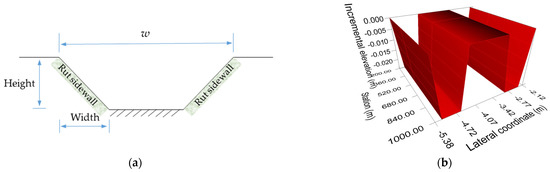
Figure 6.
Schematic view of Rutting model: (a) Simplified trapezoid rutting shape; (b) rutting model in Carsim software (in case of WHR = 10).
3.4. Modelling Lane Change
To accurately simulate the process of changing lanes as much as possible, a lane changing model was established based on hyperbolic tangent function [60], which is expressed as:
where t denotes the travel time, Δ(t) denotes the lateral offset of the vehicle at time t, and Δ0 and ΔT denote lateral offset of the vehicle at the start and end point relative to the initial centerline of lane, respectively. Ld denotes the longitudinal length during lane change. Vd denotes the average longitudinal velocity during lane change. ζ and η denote the coefficients related to Δ0 and ΔT, respectively. τ is the parameter used to characterize the urgency of a lane change in this model. In addition, LLC and RLC mean left lane change and right lane change, respectively. The vehicle changes lanes in RLC mode, as shown in Figure 7.
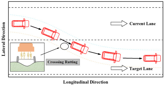
Figure 7.
Diagram of lane-change trajectory.
4. Results and Discussion
4.1. Driving Stability Analysis on Single-Factor
4.1.1. Effects of Various Driving Conditions on LA
Figure 8 shows the effects of different factors on the LA of the vehicle. During the driving process, it mainly contains four stages: smooth driving, initiating lane change, crossing rutting, and ending lane change with smooth driving. It was found that the LA maintains at around 0.1 g in the smooth driving state, with only a minor variation before and after. For a short period of time, after starting a lane change, the lateral tractive force generated during lane change demonstrates a remarkable decrease of LA. When the vehicle reaches around 500 m distance travelled (approximate 16 s), the vehicle starts to cross the rutting, and the LA increases in the opposite direction. When it came to the termination of a lane change, LA developed back to a steady trend. The LA fluctuated up and down, due to the compound effects of lateral wind and rutting.
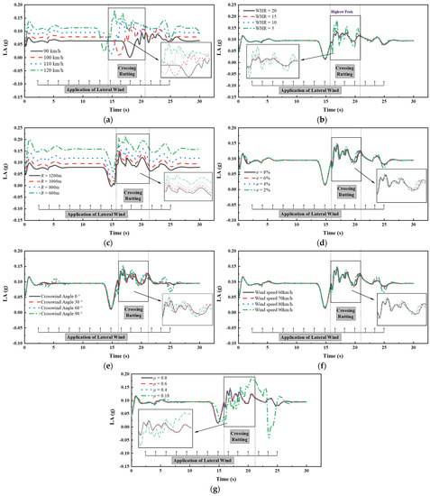
Figure 8.
Change of LA over time under various driving conditions: (a) Vehicle speed; (b) WHR of the rutting; (c) Radius of circular curve; (d) Superelevation; (e) Crosswind angle; (f) Wind speed; (g) Friction coefficient between road & tire.
To compare the effects of different factors from the perspective of spacing between the curves in Figure 8, it is indicated that the vehicle speed, WHR of rutting, radius of the circular curve, and friction coefficient of the road surface have a greater impact on LA, while the superelevation, lateral wind angle, and speed have a relativly weak influence on LA. As shown in Figure 8a,c, LA increases with the increase of driving speed, concurrently with the decrease of the radius of circular curve. The LA reaches a high level, with a maximum value approximately 0.2 g, when the driving speed and radius of the circular curve are 120 km/h and 600 m, respectively. From Figure 8b, it is found that the LA dramatically and suddenly rises to a peak when the WHR reaches 5. In addition, the maximum LA is far greater than that of other width-to-height ratios, comprising a larger amplitude of variation. As a result, the vehicle shows a higher risk of lateral offset when driving across rutting in adverse weather.
4.1.2. Effects of Various Driving Conditions on SA
Figure 9 shows the influence of different factors on SA. The SA is always smaller than the threshold value during the whole process. It is concluded that the variation of SA generally consists of four stages: rapid increase, slow increase, fluctuating increase, and the stable stage. An initial rapid increase in SA happens from 0 to 2 s, mainly due to centrifugal force during curve driving, while the slow increase in SA before the first wave crest of curve is caused by continuous application of lateral wind. The fluctuation of the SA from 15 s to 25 s is influenced by a compound effect of the lane change, across rutting, and lateral wind action. A more significant fluctuation effect on SA is shown in Figure 9b, in which the rutting is extremely severe (WHR = 5), with the largest simultaneous wave crest.
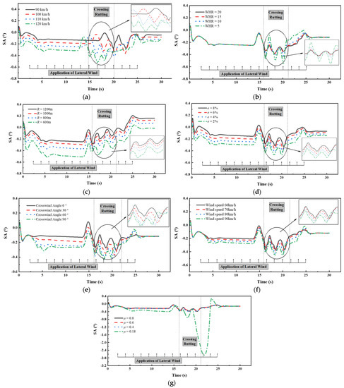
Figure 9.
Change of SA over time under various driving conditions: (a) Vehicle speed; (b) WHR of the rutting; (c) Radius of circular curve; (d) Superelevation; (e) Crosswind angle; (f) Wind speed; (g) Friction coefficient between road & tire.
As presented in Figure 9a–g, with the increase of vehicle speed, crosswind angle, and crosswind speed, a sharp decrease of the radius of the circular curve, superelevation, and pavement friction coefficient, the SA gradually increases in the negative direction. Particularly, when driving on the pavement, when the friction coefficient decreases to 0.18 (in snowy weather), the absolute value of SA increases to 2.6, and shortly afterward, it increases in the opposite direction. The vehicle appears to swing back and forth with a pretty high degree of risk, even though the SA is still smaller than the threshold value.
4.1.3. Effects of Various Driving Conditions on LTR
The influence of different factors on LTR is shown in Figure 10. The load will be transferred from the inside wheels to the outside wheels, while the vehicle is traveling in a curve segment, so the LTR firstly increases over time and sharply fluctuates up and down while driving across rutting. It is concluded that the LTRs are generally less than 0.4 in this section, which implies that the risk of roll-over is low. During initial 0–2 s, the vehicle velocity increases from 0 to constant speed, so the LTR changes in a transitional phase. In the range of 2–15 s, the LTR gradually increases, due to the effect of lateral wind, which is consistent with the previous findings of Yu et al. [61]. In the range of 15–20 s, the LTR significantly increases and then rapidly decreases, due to crossing rutting along with the effect of lateral wind. Afterward, the lateral wind gradually dissipates, so the LTR decreases and remains unchanged.
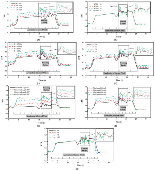
Figure 10.
Change of LTR over time under various driving conditions: (a) Vehicle speed; (b) WHR of the rutting; (c) Radius of circular curve; (d) Superelevation; (e) Crosswind angle; (f) Wind speed; (g) Friction coefficient between road and tire.
The effects of vehicle speed, radius of circular curve, superelevation, crosswind angle, and crosswind speed on LTR can be recognized as “quantitative changes but consistent with dynamic mode”, that is, vehicles are driven with similar modes in the above cases, but only varies in exact values. Note that the sudden change in LTR occurs when the WHR of rutting is 5 in Figure 10b, which is consistent with the sudden change in LA and SA, sharply fluctuating up and down.
4.1.4. Effects of Various Driving Conditions on RA
The variations of RA over time under the influence of different factors are shown in Figure 11. The simulation results for the period of time without outside adverse disturbance indicate that the RA of the vehicle is generally less than 2° and varies slightly, even when driving in a curve segment with a lateral wind. However, when it crosses a rut, the RA changes rapidly, and the instantaneous changes in RA happen to the wheels crossing the rutting, one after another, respectively. In the case of WHR equal to 5, the maximum RA of the vehicle is about 14° when driving across the rutting, which exceeds the threshold value of RA, while the maximum RA under the rest of WHR conditions does not exceed 6°, which is less than the limit value of RA. Thus, it is concluded that severe rutting damage will significantly reduce lateral stability, thus heightening the possibility of rolling over.
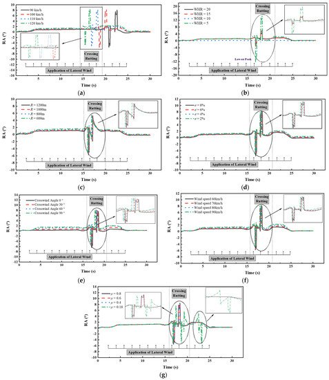
Figure 11.
Change of RA over time under various driving conditions: (a) Vehicle speed; (b) WHR of the rutting; (c) Radius of circular curve; (d) Superelevation; (e) Crosswind angle; (f) Wind speed; (g) Friction coefficient between road & tire.
Based on the results and discussions in Section 4.1.1, Section 4.1.2, Section 4.1.3 and Section 4.1.4, it is finally found that all LAs and SAs are within the threshold, but the maximum LA and maximum SA dramatically fluctuate up and down in certain cases. Regarding evaluating the roll-over stability of the vehicle, all LTRs are less than 1, showing satisfactory roll-over stability. However, the maximum RA far exceeded the threshold of 6°, which is not compliant with LTRs. So, it seems that these two indicators do not show consistency in evaluating the roll-over stability of the vehicle. Obviously, it is not thorough and accurate enough to evaluate the lateral stability with only the aid of single and independent indicators.
To overcome the limitations of a single indicator, a comprehensive indicator accounting for multiple indicators is essential for evaluating the lateral stability of the vehicle. So, in the subsequent section, Pearson’s coefficient was applied to verify the correlation between LA, SA, LTR, and RA. Then, the entropy weight method was utilized to weigh these four indicators. Finally, the comprehensive relation grade (CRG) was proposed to evaluate the effects of different factors on the lateral stability of the vehicle.
4.2. Driving Stability Analysis on Multi-Factor
4.2.1. Analysis on Safety Requirement Based on Various Driving Conditions
Figure 12 is the bar chart of the simulation results from case 1 to case 32, which presents the maximum LA, SA, LTR, and RA determined from 32 cases. From Figure 12a, it was found that the LAs were less than 0.4 g for all 32 cases, which did not exceed the safety threshold. As shown in Figure 12b, the SAs of cases 4, 11, 13, and 31 far exceeded the threshold value. These results caused the drift of the vehicle, thus leading to steering problems and large sideslips, whereas the SAs of other cases were within the threshold. From Figure 12c, it was found that all the LTRs were smaller than 1.0, presenting a high roll-over stability. However, the RAs in a large number of cases dramatically exceeded the threshold, showing high roll-over risks. Through contrastive analysis, it is known that the results of RAs were not consistent with that of LTRs, and the results of LAs were not in compliance with that of SAs, though they equally characterized the sideslip stability and roll-over stability.
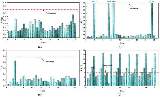
Figure 12.
Driving stability indicator based on orthogonal simulation results: (a) LA; (b) SA; (c) LTR; (d) RA.
As mentioned in the results of cases 4, 11, 13, and 31, the SAs were 59.22°, 23.98°, 58.81°, and 15.80°, which far exceeded the threshold, resulting in a vehicle with a great tendency of swaying and slip. The common characteristic of the four cases was the extremely low friction coefficient of the road surface, which was as low as 0.18, regardless of other favorable factors. So, the considerable decrease in the friction coefficient, due to snowy weather, is the leading factor that gives rise to sideslip instability [62]. In terms of RAs, their values in cases 4, 8, 12, 16, 20, 24, 28, and 32 were far beyond the threshold, even reaching over 13°. It was found that the WHRs of these cases were all equal to 5, with a rutting opening width of 1 m and a rutting depth of 4 cm. The loss of instantaneous stability, when driving across the ruts, made the vehicle susceptible to rolling over. So, the rutting condition can be accounted as a dominant factor that leads to the roll-over instability of the vehicle, which verifies the relevant vehicle dynamics simulations concerning pavement rutting [4,5,63].
The worst dynamic response occurred in case 4, with super high SA and RA. In this case, the vehicle was considered to be in a completely unstable state, which showed high susceptibility to traffic accidents. The vehicle crossed a rut with a WHR equal to 5 under the poorest road alignment and weather conditions, even with relative low driving speed. Those conditions made the vehicle have insufficient resistance to lateral slip, so it had difficulties in quickly recovering back to a stable state after encountering a rut impact, resulting in a severe loss of control and continuous slip. So, it reveals that the composite effect of adverse weather and rutting conditions shows a high probability of causing the lateral instability of the vehicle. Limiting driving speed alone is still not an effective way to ensure driving safety. Instead, preventive measures on pavement maintenance are expected to be implemented.
To determine the safety requirement of various driving conditions, it was demonstrated that dangerous results always occurred when the WHR = 5 or f = 0.18. However, several instability phenomena still happened, even solely increasing the WHR to 10 or increasing the f to 0.4. Thus, it can be deduced that multiple factors need to be controlled simultaneously. By comparing 32 cases in this study, the lateral stability of the vehicle is able to be guaranteed when the WHR is greater than 10 and the f is greater than 0.4, concurrently.
4.2.2. Correlation Analysis of Stability Indicators
Figure 13 presents the coefficient matrix of Pearson’s Correlation between indicators LA, SA, LTR, and RA. It demonstrated that the LA and SA had a strong correlation to evaluate the sideslip stability of the vehicle, with a Pearson’s coefficient of 0.8573. The LA and LTR, as well as the SA and LTR, both had acceptable correlations with each other, and their Pearson’s coefficients were greater than 0.6. Nevertheless, LTR was generally used to evaluate the roll-over stability of the vehicle, which is not incompatible with LA and SA, as given in previous studies. Likewise, the LTR and RA were normally used to characterize the roll-over stability of the vehicle. However, the Pearson’s correlation between the LTR and RA was only 0.3427, which implied the single indicator (LTR or RA) was unable to efficiently evaluate the roll-over stability of the vehicle. So, a comprehensive indicator CRG was proposed with the grey relational method to enhance this defect.
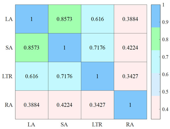
Figure 13.
Coefficient matrix of Pearson’s Correlation.
4.2.3. Evaluation of Lateral Stability Based on GRG
The grey relational grade (GRG) of each factor was obtained in Table 5 with Equations (9) and (10). In terms of LA, higher GRG values for vehicle speed, WHR, circle curve radius and friction coefficient are obtained, and all of which exceed 0.6, indicating that the vehicle speed had the most significant effect on LA, followed by the radius of circular curve, friction coefficient, WHR, superelevation, crosswind angle, and crosswind speed, respectively. For SA, the sequence of relational grades, ranked in descending order, is vehicle speed, radius of circular curve, superelevation, WHR, friction coefficient, crosswind speed, and crosswind angle, respectively. Regarding LTR, the degree of influence of the factors, in descending order, are crosswind angle, vehicle speed, radius of circular curve, WHR, wind speed, superelevation, and friction coefficient, respectively. For RA, WHR has the most obvious effect on RA, followed by vehicle speed, friction coefficient, crosswind angle, radius of circular curve, superelevation, and crosswind speed, respectively. It is notable that the CRG of WHR for RA is over 0.8, demonstrating the highest relation grade among the various factors. It implies that the pavement rutting is inclined to lead to roll-over instability.
Table 5.
Grey relational grade (GRG) of each factor.
4.2.4. Evaluation of Lateral Stability Based on CRG
The entropy weight of each indicator was obtained in Table 6. It was found that the entropy weight of LA was 0.1806, and it has the lowest weight among the four indicators, which means LA has the poorest efficiency to characterize driving safety. The entropy weight of RA is 0.3112, so it indicates the greatest significance to driving safety. Then, it is followed by SA and LTR, and their entropy weights are 0.2904 and 0.2179, respectively. So, it is deduced that roll-over instability is more likely to occur due to the variation of seven factors, relative to sideslip instability. However, Chen et al. [35] identified that passenger cars tended to experience sideslips, which is not identical to this study. The distinction may be attributed to the extended consideration of pavement rutting in the present study.
Table 6.
Entropy weight of each indicator.
Based on the GRG and entropy weight that have been obtained, a comprehensive relation grade (CRG) was calculated from Equation (15), and the results are shown in Figure 14. It indicates that vehicle speed and WHR of rutting have the leading effects on driving stability, followed by the radius of circular curve, superelevation, crosswind angle, crosswind speed, and friction coefficient, respectively. The CRGs of driving speed and WHR are both close to 0.7, which shows high significance in affecting the lateral stability of the vehicle. The radius of the circular curve and superelevation are also important factors that influence the lateral stability of the vehicle, which confirms the findings of Peng et al. [64]. The differences in CRGs between crosswind angle, crosswind speed, and friction coefficient are rather small, three factors which have nearly identical effects on the lateral stability of the vehicle.
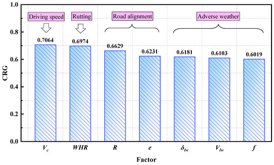
Figure 14.
The impact of driving speed, rutting, road alignment, and adverse weather on CRG.
Seven factors obviously influence driving safety. Firstly, the driving speed of the vehicle is generally the first, and most significant, factor when crossing rutting in adverse weather. Secondly, pavement rutting is the secondary factor that influences driving safety. In particular, the roll-over of the vehicle may take place while crossing the rutting immediately under poor road surface conditions with serious rutting distresses. Thirdly, road alignment is still the key consideration for driving safety, including the radius of the circular curve and superelevation in this study. If such an occasion happens with a fierce wind, the degree of risks may increase correspondingly. Moreover, the change in the road friction coefficient, due to the influence of adverse weather increases the possibility of occurring driving accidents. These unfavorable factors should be taken into account.
5. Conclusions and Prospects
In this study, a novel framework was established to implement a systematic evaluation of the lateral stability of the vehicle by considering various impact factors. The software Carsim was utilized to perform simulations. Targeted indicators were adopted to evaluate the effects of seven factors on the lateral stability of the vehicle, including LA, SA, LTR, and RA, as well as the comprehensive relation grade (CRG). The most important findings of the present study are concluded below:
- (1)
- Four targeted indicators generally experienced several stages, due to the composite effect of lateral wind, rutting, and curve driving, including a stable increasing stage, sharp increase, sharp decrease, and fluctuation. The sharp fluctuation, up and down, of four indicators was due to the process of the wheel driving into a rut and then out of a rut during the lane change. Lateral wind created a relatively weak influence on the indicators’ tendencies during the stable increasing stage.
- (2)
- LTRs were generally within the threshold, while the maximum RA far exceeded the threshold in the results of single-factor analysis, despite the fact that they both characterized the roll-over stability of the vehicle. Consequently, the application of a single indicator showed limitations in evaluating the lateral stability of the vehicle, so a comprehensive indicator was expected to enhance this defect.
- (3)
- The targeted indicators suddenly changed in a short time, due to the wandering behavior caused by rutting. Especially, this sudden change phenomenon was greatly enlarged in the case of WHR = 5. The indicator RA exceeded the threshold after driving across the rutting immediately, i.e., behaving with high driving risks. So, the instantaneous state of crossing severe rutting could be defined as a dangerous moment, which shall be cautiously prevented from the perspectives of both pavement and vehicle.
- (4)
- The vehicle was out of control, due to the joint adverse conditions with severe rutting, poor road alignment, strong wind, and low skid resistance, obviously presenting high roll-over risks. Controlling a single factor was unable to ensure driving safety, due to the notable significance of the other factors. The combined requirement of WHR > 10 and f > 0.4 was recommended to control the pavement condition for ensuring driving safety in this study.
- (5)
- LA and SA had a strong correlation to jointly evaluate the sideslip stability of the vehicle. However, the Pearson’s correlation between LTR and RA was small, so a single indicator is weak in performing good efficiency on the roll-over stability of the vehicle. A comprehensive indicator remains to be proposed to enhance evaluation efficiency.
- (6)
- A comprehensive relational grade (CRG) was, thus, proposed in the developed framework to improve evaluation performance, and it revealed that vehicle speed and the WHR of rutting had leading effects on driving safety, followed by radius of circular curve, superelevation, crosswind angle, crosswind speed, and friction coefficient, respectively.
The findings of this study revealed that the established framework performs well on evaluating the effect of different impact factors on the lateral stability of the vehicle, while driving across rutting, and particularly provides guidance to control pavement conditions from the perspective of driving safety. Despite the aforementioned contributions, a few shortcomings of this study remain to be optimized and enhanced. The major limitations lie in the quality and accuracy of the simulation, due to lack of real-world data. The consideration of factors is relative comprehensive, but in modeling the road, due to the uncertainty and variability of the hydroplaning potential, influenced by complex multi-factors, there is a case of simplified modeling. Further, only small-size passenger cars are discussed, on account of the limitation of the length of the article. Therefore, extensive in-depth investigations on the optimization of the developed framework, based on practical measured data, are envisaged in the follow-up studies. Moreover, the comparative study on the lateral stability of different vehicle types will be systematically performed, in conjunction with road maintenance recommendations for future consideration.
Author Contributions
Conceptualization, G.T., Y.J. and Y.G.; methodology, G.T. and Y.J.; software, Z.C. and Y.C.; validation, Y.G., S.W. and T.Z.; formal analysis, Z.W.; investigation, Y.C.; resources, G.T.; data curation, S.W.; writing—original draft preparation, G.T.; writing—review and editing, G.T., Z.C. and Y.J.; visualization, Y.J.; supervision, Y.G.; project administration, Y.G.; funding acquisition, Y.G. All authors have read and agreed to the published version of the manuscript.
Funding
This research was funded by National Natural Science Foundation of China (51878168).
Data Availability Statement
The data presented in this study are available on request from the corresponding author.
Acknowledgments
Thanks to funding for supporting this study. The useful support given by the National Demonstration Center for Experimental Road and Traffic Engineering Education (Southeast University) is acknowledged. The authors are sincerely grateful for their support.
Conflicts of Interest
The authors declare no conflict of interest.
References
- Xue, B.; Xu, J.; Pei, J.; Zhang, J.; Li, R. Investigation on the Micromechanical Response of Asphalt Mixture during Permanent Deformation Based on 3D Virtual Wheel Tracking Test. Constr. Build. Mater. 2021, 267, 121031. [Google Scholar] [CrossRef]
- Chen, L.; Liu, G.; Qian, Z.; Zhang, X. Determination of Allowable Rutting Depth Based on Driving Safety Analysis. J. Transp. Eng. Part B Pavements 2020, 146, 2. [Google Scholar] [CrossRef]
- Mamlouk, M.; Vinayakamurthy, M.; Underwood, B.S.; Kaloush, K.E. Effects of the International Roughness Index and Rut Depth on Crash Rates. Transp. Res. Rec. 2018, 2672, 418–429. [Google Scholar] [CrossRef]
- Cong, L.; Yang, J. Control Standard for Rut Depth Based on Simulation of Vehicle-Pavement System Dynamics. Eng. Mech. 2010, 27, 191–195. Available online: https://www.webofscience.com/wos/alldb/full-record/CSCD:4056960 (accessed on 25 February 2023).
- Zheng, B.; Huang, X.; Zhao, R.; Hong, Z.; Chen, J.; Zhu, S. Study on the Rut Control Threshold of Asphalt Pavement Considering Steering Stability of Autonomous Vehicles Based on Fuzzy Control Theory. Adv. Civ. Eng. 2021, 1–13. [Google Scholar] [CrossRef]
- Vansauskas, V.; Bogdevičius, M. Investigation into the Stability of Driving An Automobile on the Road Pavement with Ruts. Transport 2009, 24, 170–179. [Google Scholar] [CrossRef]
- Guo, X.; Zhou, B.; Zhang, C. Analysis of Rutting Index for Pavement Maintenance Based on Driving Safety on Surface Gathered Water Consideration. In CICTP 2014: Safe, Smart, and Sustainable Multimodal Transportation Systems; American Society of Civil Engineers: Reston, VI, USA, 2014; pp. 909–918. [Google Scholar] [CrossRef]
- Jia, Y.; Wang, S.; Peng, J.; Gao, Y.; Hu, D.; Zhao, X. Evaluation of Pavement Rutting Based on Driving Safety of Vehicles. Int. J. Pavement Res. Technol. 2021, 15, 457–469. [Google Scholar] [CrossRef]
- Kuznetsov, Y.V.; Moiseenko, D.A.; Plotnikov, P.V. Method for Determining the Maximum Allowable Pavement Rutting from the Condition of Ensuring the Safety of Traffic in Rainy Weather. In Proceedings of the 2021 Intelligent Technologies and Electronic Devices in Vehicle and Road Transport Complex (TIRVED), Moscow, Russia, 11–12 November 2021; pp. 1–6. [Google Scholar] [CrossRef]
- Zhao, L.; Liu, H.; Wang, L.; Wei, H. Relationship Between Driver’s Physiological Reaction and Driving Safety in Bad Weather. China J. Highw. Transp. 2016, 29, 147–152. [Google Scholar] [CrossRef]
- Jiang, K.; Yin, H.; Feng, Z. Simulation Analysis of the Influence of Crosswind on Traffic Safety of Long-Span Bridges. J. Hefei Univ. Technol. (Nat. Sci.) 2019, 42, 145–150. [Google Scholar]
- Leonaviciene, T.; Pukalskas, S.; Pumputis, V.; Kulesiene, E.; Zuraulis, V. Investigation of Factors that Have Affected the Outcomes of Road Traffic Accidents on Lithuanian Roads. Balt. J. Road Bridge Eng. 2020, 15, 1–20. [Google Scholar] [CrossRef]
- Huang, X.; Cao, Q.; Liu, X.; Chen, J.; Zhou, X. Simulation of Vehicle Braking Performance on Rainy Days Based on Pavement Surface Fractal Friction Theory. J. Jilin Univ. (Eng. Technol. Ed.) 2019, 49, 757–765. [Google Scholar] [CrossRef]
- Pomoni, M. Exploring Smart Tires as a Tool to Assist Safe Driving and Monitor Tire–Road Friction. Vehicles 2022, 4, 744–765. [Google Scholar] [CrossRef]
- Zhang, Y.; Yuan, B.; Chou, Y. Analyzing Driving Safety Using Vehicle-Water-Filled Rutting Dynamics Model and Simulation. Adv. Mater. Sci. Eng. 2022, 2022, 1–16. [Google Scholar] [CrossRef]
- Lee, H.; Taheri, S. Intelligent Tires? A Review of Tire Characterization Literature. IEEE Intell. Transp. Syst. Mag. 2017, 9, 114–135. [Google Scholar] [CrossRef]
- Jeong, H.; Liu, Y. Horizontal Curve Driving Performance and Safety Affected by Road Geometry and Lead Vehicle. Proc. Hum. Factors Ergon. Soc. Annu. Meet. 2017, 61, 1629–1633. [Google Scholar] [CrossRef]
- Žuraulis, V.; Surblys, V. Assessment of Risky Cornering on A Horizontal Road Curve by Improving Vehicle Suspension Performance. Balt. J. Road Bridge Eng. 2021, 16, 1–27. [Google Scholar] [CrossRef]
- Cvitanić, D.; Maljković, B. Determination of Applicable Adjacent Horizontal Curve Radii Using Operating Speed. Promet 2019, 31, 443–452. [Google Scholar] [CrossRef]
- Maljković, B.; Cvitanić, D. Improved Horizontal Curve Design Consistency Approach Using Steady-State Bicycle Model Combined with Realistic Speeds and Path Radii. J. Transp. Eng. Part A Syst. 2022, 148, 04022069. [Google Scholar] [CrossRef]
- Hauer, E. Safety and the Choice of Degree of Curve. Transp. Res. Rec. 1999, 1665, 22–27. [Google Scholar] [CrossRef]
- You, K.; Sun, L. Reliability Analysis of Vehicle Stability on Combined Horizontal and Vertical Alignments: Driving Safety Perspective. J. Transp. Eng. 2013, 139, 804–813. [Google Scholar] [CrossRef]
- Zhang, C.; Liang, M.; Wang, S.; Chen, J.; Shao, D. Sideslip Risk Simulation Analysis of Passenger Car Braking Behavior on Expressway Curved Sections. China J. Highw. Transp. 2015, 28, 134–142. [Google Scholar] [CrossRef]
- Jackson, T.L.; Sharif, H.O. Rainfall Impacts on Traffic Safety: Rain-related Fatal Crashes in Texas. Geomat. Nat. Hazards Risk 2016, 7, 843–860. [Google Scholar] [CrossRef]
- Peng, T.; Guan, Z.; Zhang, R.; Dong, J.; Li, K.; Xu, H. Bifurcation of Lane Change and Control on Highway for Tractor-Semitrailer under Rainy Weather. J. Adv. Transp. 2017, 2017, 1–9. [Google Scholar] [CrossRef]
- Wang, C.; Huang, H.; Xu, S. The Study on the Influence of Gust Wind on Vehicle Stability. In Applied Mechanics and Materials; Trans Tech Publications Ltd.: Bäch, Switzerland, 2014; Volume 598, pp. 198–201. [Google Scholar] [CrossRef]
- Žuraulis, V.; Sivilevičius, H.; Šabanovič, E.; Ivanov, V.; Skrickij, V. Variability of Gravel Pavement Roughness: An Analysis of the Impact on Vehicle Dynamic Response and Driving Comfort. Appl. Sci. 2021, 11, 7582. [Google Scholar] [CrossRef]
- Sekulic, D.; Vdovin, A.; Jacobson, B.; Simone, S.; Moe, J.S. Effects of Wind Loads and Floating Bridge Motion on Intercity Bus Lateral Stability. J. Wind. Eng. Ind. Aerodyn. 2021, 212, 104589. [Google Scholar] [CrossRef]
- Wang, B.; Xu, Y. Safety Analysis of a Road Vehicle Passing by a Bridge Tower under Crosswinds. J. Wind. Eng. Ind. Aerodyn. 2015, 137, 25–36. [Google Scholar] [CrossRef]
- Chen, F.; Peng, H.; Ma, X.; Liang, J.; Hao, W.; Pan, X. Examining the Safety of Trucks under Crosswind at Bridge-Tunnel Section: A Driving Simulator Study. Tunn. Undergr. Space Technol. Inc. Trenchless Technol. Res. 2019, 92, 103034. [Google Scholar] [CrossRef]
- Xu, D.; Wang, G.; Qu, L.; Ge, C. Robust Control with Uncertain Disturbances for Vehicle Drift Motions. Appl. Sci. 2021, 11, 4917. [Google Scholar] [CrossRef]
- Mansor, S.; Passmore, M.A. Effect of Rear Slant Angle on Vehicle Crosswind Stability Simulation on A Simplified Car Model. Int. J. Automot. Technol. 2013, 14, 701–706. [Google Scholar] [CrossRef]
- Hassan, M.A.; Abdelkareem, M.A.A.; Moheyeldein, M.M.; Elagouz, A.; Tan, G. Advanced study of tire characteristics and their influence on vehicle lateral stability and untripped rollover threshold. Alex. Eng. J. 2020, 59, 1613–1628. [Google Scholar] [CrossRef]
- Xiao, F.; Hu, J.; Jia, M.; Zhu, P.; Deng, C. A novel integrated control framework of AFS, ASS, and DYC based on ideal roll angle to improve vehicle stability. Adv. Eng. Inform. 2022, 54, 101764. [Google Scholar] [CrossRef]
- Chen, F.; Peng, H.; Shao, X.; Pan, X. Comparative analysis of driving stability between truck and car under crosswind. J. Harbin Inst. Technol. 2021, 53, 10–16. [Google Scholar] [CrossRef]
- Wang, Y.; Hu, X. Simulation of roll stability of a van in cross-wind. Appl. Mech. Mater. 2013, 397–400, 401–404. [Google Scholar] [CrossRef]
- Wang, L.; Chen, X.; Chen, H. Influencing factors on vehicles lateral stability on tunnel section in mountainous expressway under strong wind: A case of Xi-Han highway. Adv. Civ. Eng. 2020, 2020, 1–11. [Google Scholar] [CrossRef]
- Yin, Y.; Wen, H.; Sun, L.; Hou, W. Study on the influence of road geometry on vehicle lateral instability. J. Adv. Transp. 2020, 2020, 1–15. [Google Scholar] [CrossRef]
- Alrejjal, A.; Ksaibati, K. Impact of Combined Alignments and Different Weather Conditions on Vehicle Rollovers. KSCE J. Civ. Eng. 2022, 26, 893–906. [Google Scholar] [CrossRef]
- Tian, L.; Li, Y.; Li, J.; Lv, W. A simulation based large bus side slip and rollover threshold study in slope-curve section under adverse weathers. PLoS ONE 2021, 16, e0256354. [Google Scholar] [CrossRef] [PubMed]
- Zheng, B.; Huang, X.; Tang, J.; Chen, J.; Zhao, R.; Hong, Z.; Tang, T.; Han, M. Evaluation on Braking Stability of Autonomous Vehicles Running along Curved Sections Based on Asphalt Pavement Adhesion Properties. J. Adv. Transp. 2022, 2022, 1–20. [Google Scholar] [CrossRef]
- Siringoringo, D.M.; Fujino, Y.; Yabe, M. Investigation on vehicle lateral instability when crossing a curved highway bridge during an earthquake. Struct. Infrastruct. Eng. 2021, 17, 720–740. [Google Scholar] [CrossRef]
- Zhang, C.; Xia, Q.; He, L. A Study on the Influence of Sideslip Angle at Mass Center on Vehicle Stability. Automot. Eng. 2011, 4, 5–10. [Google Scholar] [CrossRef]
- Wang, Z.; Dong, M.; Gu, L.; Rath, J.; Qin, Y.; Bai, B. Influence of Road Excitation and Steering Wheel Input on Vehicle System Dynamic Responses. Appl. Sci. 2017, 7, 570. [Google Scholar] [CrossRef]
- You, K.; Sun, L.; Gu, W. Risk Analysis-based Identification of Road Hazard Locations Using Vehicle Dynamic Simulation. J. Southeast Univ. Nat. Sci. Ed. 2012, 42, 150–155. [Google Scholar] [CrossRef]
- Wu, X.; Fu, S.; Guo, L. Study on Highway Alignment Optimization Considering Rollover Stability Based on Two-Dimensional Point Collision Dynamics. Appl. Sci. 2022, 13, 509. [Google Scholar] [CrossRef]
- Zhang, X.; Yang, Y.; Guo, K.; Lv, J.; Peng, T. Contour line of load transfer ratio for vehicle rollover prediction. Veh. Syst. Dyn. 2017, 55, 1748–1763. [Google Scholar] [CrossRef]
- Ministry of Transport of the People’s Republic of China. Design Specification for Highway Alignment (JTG D20-2017); China Communications Press: Beijing, China, 2018. (In Chinese)
- Kwonhee, S.; Hiseak, Y. Numerical Investigations of the Crosswind Stability of the Korean Light Tactical Vehicle During Airlift. J. Mech. Sci. Technol. 2017, 31, 1067–1072. [Google Scholar] [CrossRef]
- Wang, F.; Yu, Y.; Zhao, X.; Xu, J.; Xie, T.; Deresa, S. Performance Evaluation of Reinforced Recycled Aggregate Concrete Columns under Cyclic Loadings. Appl. Sci. 2019, 9, 1460. [Google Scholar] [CrossRef]
- Jiang, R.; Sun, T.; Liu, D.; Pan, Z.; Wang, D. Multi-Objective Reliability-Based Optimization of Control Arm Using MCS and NSGA-II Coupled with Entropy Weighted GRA. Appl. Sci. 2021, 11, 5825. [Google Scholar] [CrossRef]
- Wang, L.; Li, R.; Wang, C.; Liu, Z. Driver injury severity analysis of crashes in a western China’s rural mountainous county: Taking crash compatibility difference into consideration. J. Traffic Transp. Eng. 2021, 8, 703–714. [Google Scholar] [CrossRef]
- Li, P.; Sun, C.; Huang, M.; Jiang, S.; Khan, M.D. Water Accumulation and Anti-Sliding Decay Characteristics of Freeway Pavement at Superelevation Transitions. Road Mater. Pavement Des. 2022, 1–16. [Google Scholar] [CrossRef]
- Fwa, T.F.; Pasindu, H.R.; Ong, G.P. Critical Rut Depth for Pavement Maintenance Based on Vehicle Skidding and Hydroplaning Consideration. J. Transp. Eng. 2012, 138, 423–429. [Google Scholar] [CrossRef]
- Rana, M.M.; Hossain, K. Impact of Autonomous Truck Implementation: Rutting and Highway Safety Perspectives. Road Mater. Pavement Des. 2022, 23, 2205–2226. [Google Scholar] [CrossRef]
- Žuraulis, V.; Surblys, V.; Šabanovič, E. Technological Measures of Forefront Road Identification for Vehicle Comfort and Safety Improvement. Transport 2019, 34, 363–372. [Google Scholar] [CrossRef]
- Hui, B.; Tsai, Y.J.; Guo, M.; Liu, X. Critical assessment of the impact of vehicle wandering on rut depth measurement accuracy using 13-point based lasers. Measurement 2018, 123, 246–253. [Google Scholar] [CrossRef]
- Besselink, I.J.M.; Achrifi, S.; Nijmeijer, H. Lateral vehicle dynamics on rutted roads. In The IAVSD International Symposium on Dynamics of Vehicles on Roads and Tracks; Springer: Cham, Switzerland, 2019; pp. 1242–1251. [Google Scholar] [CrossRef]
- Yan, J.; Zhang, H.; Hui, B. Driving Safety Analysis Using Grid-Based Water-Filled Rut Depth Distribution. Adv. Mater. Sci. Eng. 2021, 2021, 1–13. [Google Scholar] [CrossRef]
- Zhou, B.; Wang, Y.; Yu, G.; Wu, X. A lane-change trajectory model from drivers’ vision view. Transp. Res. Part C Emerg. Technol. 2017, 85, 609–627. [Google Scholar] [CrossRef]
- Yu, H.; Wang, B.; Li, Y.; Zhang, M. Driving Risk of Road Vehicle Shielded by Bridge Tower under Strong Crosswind. Nat. Hazards 2019, 96, 497–519. [Google Scholar] [CrossRef]
- Chen, S.; Chen, F. Simulation-Based Assessment of Vehicle Safety Behavior under Hazardous Driving Conditions. J. Transp. Eng. 2010, 136, 304–315. [Google Scholar] [CrossRef]
- Chen, D.; Chen, L.; Qian, Z. Impact of Pavement Rutting on Vehicle Safety: A Closed-Loop Assessment Method. Road Mater. Pavement Des. 2022, 1–16. [Google Scholar] [CrossRef]
- Peng, J.; Chu, L.; Wang, T.; Fwa, T.F. Analysis of Vehicle Skidding Potential on Horizontal Curves. Accid. Anal. Prev. 2021, 152, 105960. [Google Scholar] [CrossRef]
Disclaimer/Publisher’s Note: The statements, opinions and data contained in all publications are solely those of the individual author(s) and contributor(s) and not of MDPI and/or the editor(s). MDPI and/or the editor(s) disclaim responsibility for any injury to people or property resulting from any ideas, methods, instructions or products referred to in the content. |
© 2023 by the authors. Licensee MDPI, Basel, Switzerland. This article is an open access article distributed under the terms and conditions of the Creative Commons Attribution (CC BY) license (https://creativecommons.org/licenses/by/4.0/).