1. Introduction
Nowadays, mobile phones have become an indispensable part of society, impacting human lives in various aspects. Mobile phones and especially smartphones have revolutionised the methods of communication, connectivity and information access and have become the main devices used to access the internet. These phones enable real-time communication through calls and texts, effortlessly connecting people across the world. Through 4G data connections, mobile phones provide access to various messaging apps and a vast store of information at our fingertips. Additionally, mobile phones provide a lifeline during emergencies, allowing users to call for help, receive emergency alerts, and access critical information during natural disasters or other crises.
Despite all the positive aspects brought about by this upward trend, from a technological point of view, mobile phones also introduce a series of elements that negatively impact society from a legal standpoint. The small dimensions, low battery consumption, ease of obtaining a SIM card with data and internet services, and extremely easy access to the internet make mobile phones a very dangerous device in areas where electronic devices are not allowed. One of the environments where phones are strictly prohibited due to security risks is a prison. Despite the regulations that completely prohibit mobile phones in prisons, there are prisoners who manage to gain access to such devices and subsequently access the internet.
Over the years, several researchers have studied various security aspects related to mobile networks, as well as the possibility of increasing their resilience. In [
1], the authors made a thorough survey regarding jamming attacks that can be performed on new-generation communication systems and their effect on LTE systems. Several jamming methods that were found to be disruptive for the LTE system were enumerated and, in the final part of this paper, several research directions for increasing the system resilience are highlighted. The authors of [
2] also presented a comprehensive survey regarding the security attacks on an LTE system, which were classified based on the level they are performed on the OSI protocol stack. For each type of attack, the causes, implications and possibility of defence are presented. The authors also underlined the fact that there are still unsolved security breaches in the 5G air interface and offered several directions for future research. In another survey [
3], the authors presented ample material regarding jamming attacks on different wireless networks, such as WLANs, cellular systems, Zigbee, Bluetooth, LoRa and RFID links, as well as anti-jamming strategies that have been identified. In [
4], the authors presented a radio jammer for suppressing a detonation code transmitted using remote-controlled detonators; it was implemented with an optoelectronic device that produced replicas of a useful radio signal that degraded the quality of the transmitted signal. The device was simulated, designed and implemented as a prototype that validated the results. The authors of [
4] presented a novel approach for implementing a jammer against wireless detonating devices by using optoelectronic equipment that generated replicas of the transmitted signal to destructively interfere with the correct one, and thus, reduce the signal-to-interference ratio, making the detonating code unrecognisable. The device was designed, developed and tested in MatLab, and then implemented as a prototype. In [
5], the authors studied the vulnerability of LoRa radio links using single-tone, multi-tone and band-jamming strategies, with the results showing that this type of radio connection is robust to the type of jamming, with tone jamming being the most harmful one. The authors of [
6] studied issues related to security aspects of low-power wide-area networks, including a review of the recently published research papers relevant to this domain, and identifying the critical attack vectors, as well as the most suitable protection and defence mechanisms. In [
7], the authors studied two types of jammers, namely, the random signal jammer and the phase shift signal jammer, which were tested against the 5G signal. In [
8], the authors proposed a prototype for a cascaded detector–jammer that can block a radio signal for 2G, 3G and 4G networks within a small distance range to be used for protected areas like prisons, examination rooms, confidential facilities and military bases. The authors of [
9] presented an analytical procedure for evaluating the anti-jamming capacity of an underwater acoustic direct sequence spread spectrum (DSSS) communication system under different types of jammers (single tone, partial band and wideband) and compared the theoretical results with the ones obtained based on simulations. In [
10], the authors mathematically evaluated and simulation-tested the performances of a deep-reinforcement-learning-based anti-jamming method for different types of jammers and designed a jamming algorithm that was found to be effective with the anti-jamming algorithm to prove its limitations. In [
11], the authors proposed a reinforcement-learning-based jamming algorithm and its universal software radio peripheral (USRP) implementation showed that it was effective for 5/6G communications systems that involved the orthogonal frequency-division multiplexing (OFDMA) technique.
As one can see, some of the abovementioned research covered only partial aspects of the issues. Some analysed the vulnerability of mobile communication technologies to jamming, while other solutions performed long-term jamming in all downlink (DL) bands of all mobile communication bands (e.g., jamming systems for explosive improvised devices). Also, when searching the literature, we found few results regarding the practical implementation of USRP-based narrowband jamming signals based on monitoring the downlink connection, and no results for the specific communication landscape offered in Bucharest.
The originality of this study consisted of the fact that it involved, at first, an analysis of the spectral domain used by each mobile communication operator, and based on this, the mobile service operator that could potentially be selected by a terminal that offered the best network parameters was chosen, and the jamming was performed only on the DL frequency of the selected service. The authors choose not to use broadband jamming for the entire DL frequency range, but only on that particular DL channel of the service with significant parameters selected by a user in a limited time interval.
Within this study, several objectives were aimed towards:
To determine whether downlink jamming using the SDR Hack-RF can be performed in two different scenarios: when the position of the receiver was neighbouring the cell and when it was at the edge of the cell by considering two different values for the strength of the received signal.
To evaluate the possibility of using reactive jamming on the downlink connection when the receiver was at the edge of the cell, to evaluate the technical limitation when the receiver was neighbouring the cell and to identify a solution for intelligent jamming.
To develop an intelligent jamming system using commercial equipment that can be exploited in indoor conditions to react to a downlink signal when an amplitude of the monitored uplink signal above a predetermined threshold is detected.
Based on the abovementioned objectives, the main contributions of this study are as follows:
Intelligent jamming consists of hardware and software that work together to block any radio event in the specific band on the DL connection, which is enabled by an amplitude above a threshold set based on radio measurements detected on UL channels.
Monitoring the DL connection provides knowledge of the availability of the network operators at a specific monitoring radio point. The list of available bands with their central frequencies is provided to Hack-RF. Python code developed from scratch is powered with the list of available DL frequencies. Based on this, it calculates the corresponding UL frequencies and starts monitoring them. An amplitude above −60 dBm on a UL-monitored frequency enables an emission on the corresponding DL frequency for 15 s. After all the input parameters are set, the jamming system is autonomous in its decisions.
The intelligence component of the process consists of the following:
- ⮚
Analysis of the spectral use by mobile communication operators.
- ⮚
The selection of the mobile communications service that has the most significant network parameters and that would cause a mobile device to register in that band/technology.
- ⮚
Jamming only on the DL frequency of the selected service for a limited period set by the operator (a few seconds).
The originality here lies in the fact that broadband jamming is not performed for all DL frequencies in the range including 800, 900, 1800, 2100 and 2600 MHz, but only uses targeted jamming on the DL channel of the service with significant parameters selected by the operator and in a limited period. This reduces the exposure to electromagnetic radiation of people who are in the secure area; reduces the electricity consumption of the jamming system; avoids electromagnetic interference with other electronic communication systems; and, of course, obtains results from jamming the radio connections of the mobile devices in areas where their usage is prohibited.
This article is structured as follows:
Section 2 presents an overview of the radio downlink connections of the mobile network operators in Bucharest, Romania.
Section 3 describes some theoretical aspects of jamming systems, conditions for jamming and simulations of the theoretical scenarios. Subsequently,
Section 4 showcases the test results, confirming both the validity and sustainability of the proposed methods for analysing jamming possibilities, each with its environmental conditions and limitations. This paper concludes in
Section 5, with discussions, remarks and future works.
2. Downlink Connection Landscape of the Mobile Operators in Bucharest
Using a radio spectrum analyser consisting of Nestor software and TSMA 6 hardware [
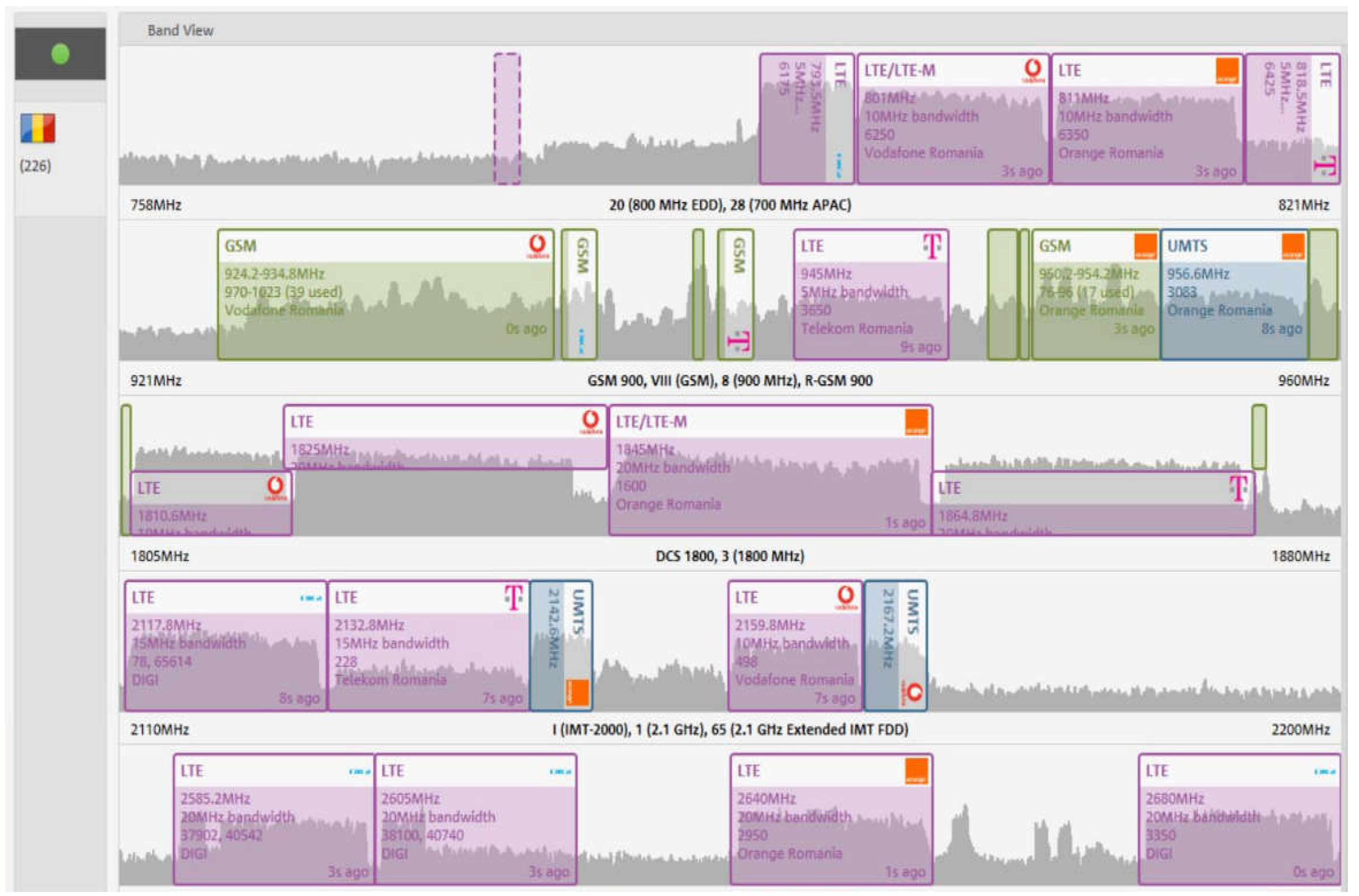
13], interesting results and an overview of the network operators’ availability in the radio monitoring point were obtained. An omnidirectional antenna for monitoring the downlink connections was used and it can be observed that the radio spectrum allocated to mobile network operators was very crowded. Nestor software based on TSMA 6 hardware is a very useful tool for network operators to analyse their radio coverage and make field measurements of the services they provide. After these measurements are completed, operators analyse the data obtained and, if necessary, make modifications or implement new cells to improve the coverage and service quality for subscribers.
As depicted in
Figure 1, all Romanian network operators had a radio presence at the monitoring point, providing different technologies across several frequency bands. In Romania, network operators have made significant changes, such as improving the spectral efficiency by deploying LTE technologies in lower bands, like 800/900 MHz and 2100 MHz.
Figure 1 shows interesting measurements that are characteristic of downlink connections:
- ⮚
GSM technology is represented in green, and it is provided by all Romanian operators in the 900 MHz band, typically in channels 1–124.
- ⮚
UMTS technology is indicated in blue, and it can be observed that network operators have significantly reduced their radio presence in providing UMTS services. The trend in Romania is to exclude this technology from future networks to make room for 5G SA.
- ⮚
LTE and LTE-M technologies are shown in purple. They are provided by all Romanian operators across different frequency bands, each with various bandwidths.
Table 1 presents the frequency bands and technologies provided in Romania by Digi Mobil and are leased from the authorities. These are identified by the radio frequency channel and the central frequency. For our experiment, it was very important to know the radio spectrum allocation for these frequency bands and technologies. However, the most important aspect was to conduct radio measurements at the specific point of interest to be aware of the availability of the network.
Based on the data in
Table 1 and the radio measurements conducted, we could conclude that Digi Mobil allocates frequency bands and technologies based on the specific areas they aim to cover. For rural areas that require signal coverage, Digi Mobil tend to utilise technologies in lower frequency bands. Conversely, in urban areas, the cell density is increased, and higher frequency bands are used to deliver quality services.
In the following sections, we focus on presenting our experiments and radio measurements on services provided by Digi Mobil. Although we conducted measurements on all available Romanian network operators, we established that the results obtained in the laboratory, which depended on the network operator’s radio configuration strength, are worth presenting to the scientific community.
The lab setup for the measurements of the radio spectrum allocated to Romanian network operators consisted of the following:
TSMA 6 was the hardware platform for running the software Nestor produced by Rohde & Schwarz; its capabilities and parameters setup used in our measurement campaign are detailed in the following. For all the measurements, we used an omnidirectional antenna without gain. From the settings, we selected scanning all available bands (700 MHz, 800 MHz, 900 MHz, 1800 MHz, 2100 MHz and 2600 MHz) and technologies (GSM, UMTS and LTE) that network operators provided in the area (we know that in other areas/continents, mobile technologies are provided in different bands than in Europe). All available technologies and bands are displayed in
Figure 1 for all network operators that provided services that covered our range of measurements.
After we selected all the bands that were available, corresponding to our regulatory authority, we started measuring in automatic channel detection mode, which was provided by the spectrum analyser. The spectrum analyser offered an overview of the available bands and decoded all the technologies that were provided.
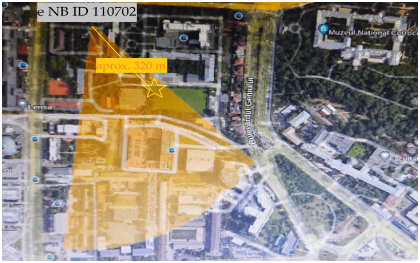
Figure 2 illustrates the estimation of the propagation of the network cell eNodeB ID 110702 installed near the measurement point marked with a yellow star at approximately 320 m from the cell. The estimation of the covered area was undertaken manually, with other measurements on the field based on the receiving signal level at different points in the yellow sector, which was corroborated with the information provided by
Combain.com regarding the establishment of the cell.
In LTE technologies, to better understand the performance limits of the network, the parameters NB RSRP, NB RSSI and NB RSRQ were introduced to characterise the radio link between the network and mobile devices. Network operators use these measurements to optimise their networks, ensure seamless handovers between cells and provide quality service to subscribers.
RSRP stands for reference signal received power and it is used to measure the received power of the reference signals from the base station in a wireless communication system. NB RSRP is used to measure the power level of the reference signals transmitted by the base station. It is typically reported in dBm and the range of this measurement depends on the receiver’s capability, but it is usually around −140 dBm to −44 dBm for typical cellular networks. In our case, NB RSRP was −58.82 dBm, which indicates that the signal was very good when received at the level of the spectrum analyser antenna.
NB RSSI means received signal strength indicator (RSSI) in LTE (long-term evolution) networks; it is typically measured in dBm and represents the power level of the received signal from the serving cell. The acceptable RSSI values can vary depending on factors such as the network configuration, deployment conditions and device sensitivity. However, there are general ranges and guidelines that can be considered. Strong signal strength (high RSSI) values above −50 dBm are considered very strong signals. In our measurements, we obtained −33.43 dBm, and thus, we can consider that the value obtained characterised a very strong serving cell.
NB RSRQ means reference signal received quality and is used to measure the quality of the received reference signals from a base station or cell. The RSRQ values typically range from negative infinity to a positive value measured in decibels (dB). Acceptable RSRQ limits can vary depending on the specific network and deployment conditions. An RSRQ above −15 dB is considered a very good indicator of the quality of the serving cell. In our measurements, we obtained RSRQ −16.90 dB, and thus, the quality of the radio services provided was considered fair to adequate.
In the Nestor menu, supplementary information regarding the measurements is available;
Figure 3 illustrates the downlink connection qualities in green (for very good quality signal), yellow (for poor quality) and red (very poor quality) for the Digi Mobil operator’s LTE technology. It includes all available and measured PCIs, along with the key parameters that describe the quality or signal strength of the received services. The spectrum analyser was configured to measure all bands used for LTE technology in the Europe region, with a threshold set above the noise level at −120 dBm.
In
Table 2, line 1 presents the serving cell, which was characterised by the following:
- ⮚
The evolved cell identifier was 28339794.
- ⮚
The cell ID was 82.
- ⮚
The EARFCN was 6175.
- ⮚
The radio band was 20.
- ⮚
The physical cell identity (PCI) was 178.
- ⮚
The EARFCN central frequency was 793.5 MHz.
- ⮚
The level received for NB-RSRP was −58.82 dBm.
- ⮚
The level received for NB-RSSI was −33.43 dBm.
- ⮚
The NB-RSRQ was −16.90 dB.
- ⮚
The signal-to-interference plus noise ratio (SINR) value was 0.17 dB.
- ⮚
The delay spread was 12 ns.
The radio spectrum analyser was set to −120 dBm because we considered that any signal measured below that value could not be taken into consideration since it would be under the limit of mobile devices’ sensitivity. The spectrum analyser sensitivity, after successful physical cell ID decoding according to the user manual, was −130 dBm.
Therefore, as corroborated with the mobile device sensitivity, which in LTE technology for high-end smartphones and mobile devices is typically in the range of −120 dBm to −115 dBm, we considered that the noise level was below −120 dBm. Measurements made with the spectrum analyser were not influenced by the used antenna or by the length of the cable. The antenna we used was an omnidirectional one with a 0.3 m cable length, and thus, the losses on the cable length were insignificant.
The PCI 178 was the serving cell in the 800 MHz band providing LTE technologies. As shown in
Figure 3, the parameter NB-RSRP, displayed in green, indicated a very strong received power from the network.
By comparing PCI 178 with PCI 177 (line 2 in
Table 2), even though these cells were installed on the same cell tower, we can observe that the NB-RSRQ for PCI 177 was −21.47 dB at the radio-monitoring point, signifying a poor service quality, as indicated in red.
Lines 2–8 presented in
Table 2 are considered neighbours of PCI 178. The characteristic parameters for lines 2–8 correspond with poor connection quality.
These parameters presented are dynamic and subject to variations, depending on the mobile operator, as well as on the dynamics of the resources requested by subscribers, the dynamics of subscribers in the geographical area and the environment in which the transmission takes place.
In conclusion, as inferred from
Table 1 and
Table 2 and corroborated with the measurements presented in
Figure 1,
Figure 2 and
Figure 3, even if the Digi Mobil operator leased a wide variety of frequency bands from the Romanian authority, the implementation of technologies in different radio-covered areas primarily depended on the subscriber demands and complied with the National Communication Code. Once the downlink channels and technologies available were identified, based on those frequencies, the uplink frequencies could be calculated.
The uplink frequencies based on radio measurements at the point of interest from Digi Mobil are presented below:
The GSMs in the 900 MHz band were the following: radio frequency channels 1–3 (UL frequency 890.2–890.6 MHz), 5–6 (UL frequency 891–891.2 MHz) and 22–23 (UL frequency 894.4–894.6 MHz).
The LTEs were the following: in the 800 MHz band—radio frequency channels 24,175, central frequency 834,5 MHz and bandwidth 5 MHz; in the 2100 MHz band—radio frequency channels 131,150, central frequency 19,278 MHz and bandwidth 15 MHz; and in 2600 MHz band—TDD modulation, radio frequency channels 37,902, central frequency 2585.2 MHz and bandwidth 20 MHz, and TDD modulation, radio frequency channels 3350, central frequency 2680 MHz and bandwidth 20 MHz.
Since the radio configuration of the Digi Mobil network provider was determined, including the uplink and downlink frequencies and the implemented technologies, the theoretical aspects of the used methods for jamming can be presented. The radio measurements conducted on downlink connections revealed the availability of the technologies in different frequency bands.
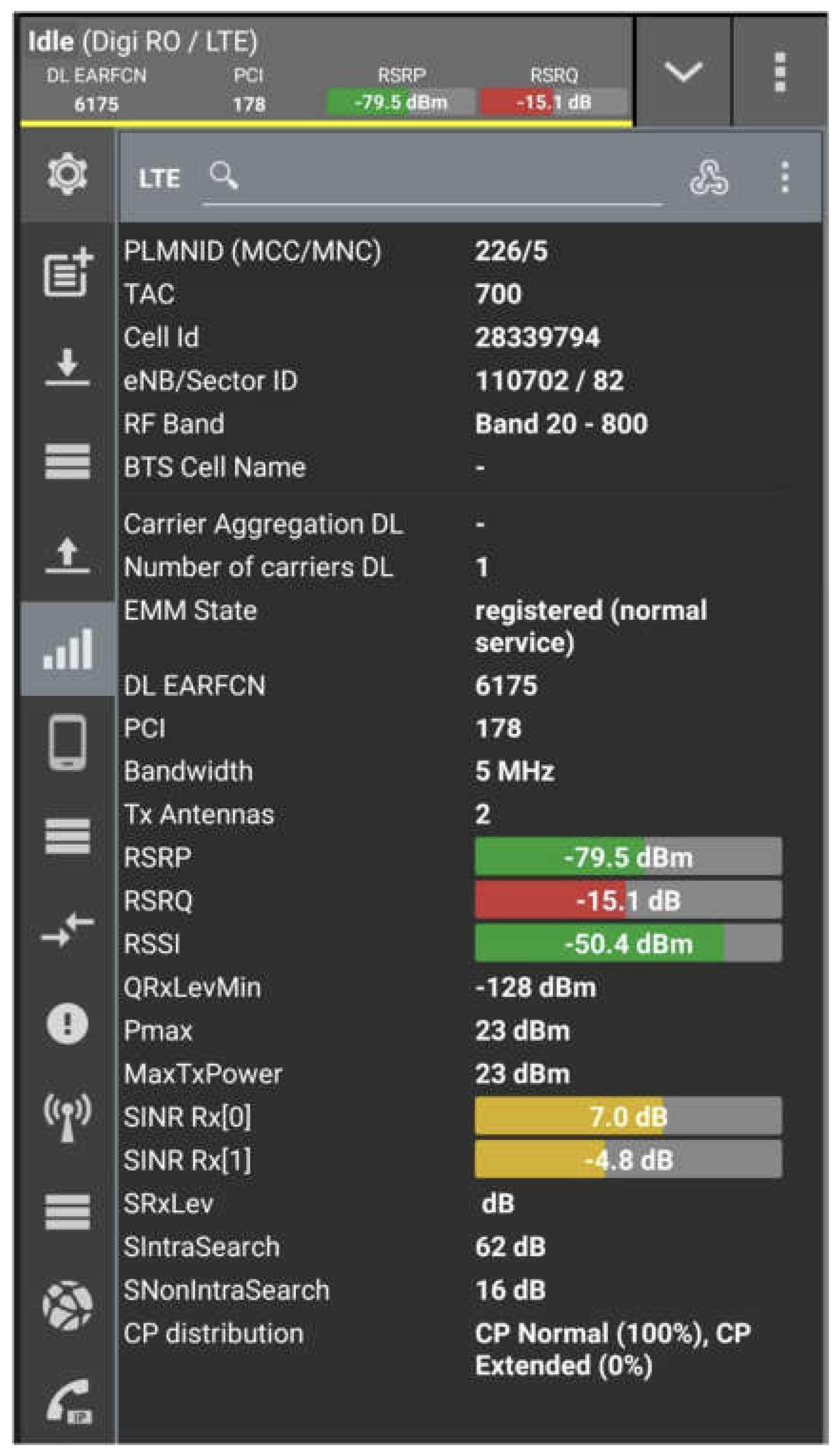
Measurements on a smartphone with a special software called QualiPock, which can display the naturally chosen band and technology without any influences, were also performed. As shown in
Figure 4, the smartphone was registered in band 20 at 800 MHz using FDD modulation with an RSSI of −50.4 dBm, RSRP of −79.5 dBm and RSRQ of −15.1 dB. Based on these measurements, we could conclude that the quality of the connection was not very good, despite the signal level being strong.
The scenario of unavailability of LTE technology provided for the 800/2100/2600 MHz bands is frequently encountered in prisons and facilities with thick walls containing a lot of steel. When the LTE 800 band becomes unavailable or is jammed, smartphones tend to select GSM 900 MHz as an alternative. To precisely determine which GSM channel is preferred, measurements were conducted, and the results are illustrated in
Figure 5. The mobile phone selected channel number 23, with a downlink frequency of 939.6 MHz, and the received signal level was −62 dBm, indicating a good connection. To perform a jamming signal on GSM channel 23, it was necessary to calculate the uplink frequency. Considering the 45 MHz difference between the downlink and uplink frequencies, the uplink frequency was determined to be 894.6 MHz.
Based on the radio measurements, it was possible to design a jamming system adapted for GSM technology in the 900 MHz band for the Digi Mobil operator. Jamming on GSM technology is not quite new in this field, as the radio spectrum used in GSM is susceptible to interference due to the vulnerabilities inherent in the technology.
3. Intelligent Jamming
To disrupt communications through jamming, it is sufficient to block either the downlink or uplink frequencies of the smartphones. Uplink and downlink are fundamental concepts in telecommunications that refer to the direction of data transmission within a communication system, especially in wireless networks [
12].
In a wireless communication system, like a cellular network, the uplink and downlink operate on separate frequency bands to facilitate simultaneous two-way communication. This frequency division ensures non-interference between uplink and downlink transmissions to promote efficient and balanced communication between users and the network infrastructure.
The principle of jamming involves emitting interfering signals on the same frequencies as the target device’s communication signals but with greater power and the same bandwidth. This interference overwhelms the target system, rendering it unable to effectively transmit or receive information. The suitable scenarios for the experiments we took into consideration were the following [
5]:
Frequency matching: jamming devices are designed to transmit signals on the same frequency bands or channels used by the target system.
Continuous jamming: Jamming can be continuous, where a constant jamming signal is transmitted, or it can be pulsed, where jamming signals are emitted intermittently. Pulsed jamming can make it more challenging for the target system to adapt or counteract the interference.
Partial-band jamming (PBJ): jamming can target specific frequencies or frequency bands, while broadband jamming covers a wider range of frequencies.
The choice depends on the goal and the capabilities of the jamming device.
In all our test experiments, we used frequency-match jamming, continuous jamming and partial-band jamming.
Partial-band jamming is a strategy that disrupts a specific portion of the total bandwidth. This is achieved by transmitting additive white Gaussian noise (AWGN) within that specific band section. When the jamming power remains constant, the efficiency of this approach is directly related to the proportion between the bandwidth used for jamming and the bandwidth of the original signal.
Jamming can be used for illegal purposes, such as disrupting commercial communication systems, GPS signals or even Wi-Fi networks. To mitigate the effects of jamming, organisations and governments employ techniques like frequency hopping, spread-spectrum communication and encryption to make it more challenging for jammers to interfere with their systems. Additionally, they invest in signal-analysis and jamming-detection technologies to identify and counter jamming attempts.
With the increasing prominence of SDR technology, jammers have gained greater adaptability and simplicity in usage, becoming conveniently available for online purchase at reasonably affordable costs. However, the improper use of such devices poses a significant societal challenge, as it undermines the reliability and safety of critical wireless communications. Furthermore, there is a potential economic impact that harms the earnings of mobile service providers in the event of a large-scale attack.
In this study, we conducted experiments on jamming in downlink bands based on the sensibility of the mobile phone, signal noise and strength of the signal level of the network; interesting results were obtained. Intelligent jamming methods consist of analysing the availability of the mobile network operators at a specific point of interest. To achieve this, a Python code was developed and the SDR Hack-RF Sweep was used to measure the amplitude of the uplink frequency. Based on these measurements, a jamming signal was emitted on the corresponding downlink frequency [
12].
Within the context of this study, based on the theoretical considerations regarding the LTE telecommunications technologies presented above, a jamming system was tested and interesting results were obtained under laboratory conditions. First, we jammed the downlink connections received at the radio measurement point, and second, based on monitoring the amplitude of the uplink connection, we continuously jammed the corresponding downlink frequency channels.
3.1. Radio Sensitivity of a Mobile Phone
To determine the effectiveness of the jamming device, it is very important that when the mobile phone tries to register in the network, it is aware of its position in the cell, whether it is within the cell’s core coverage area, whether there are neighbouring cells or whether it is at the cell’s coverage edge. Several measurements must be undertaken to verify the signal strength of the received signal. The radio sensitivity of a mobile phone refers to its ability to detect radio signals from mobile communication networks (such as signals from cell towers) in conditions of weak reception or when the signal is faint. The sensitivity of a smartphone can vary depending on several factors, including the model, manufacturer and technology used. In general, the signal sensitivity level at which a smartphone can operate efficiently falls within the range of approximately −90 dBm to −120 dBm.
3.2. Minimal/Maximal Output on DL LTE Technology in 800 MHz Band
Radio measurements were undertaken for the downlink connection, and the range for received signal level was found to be between −50 and −80 dBm neighbouring the cell (approximately 200 m), which corresponded to a good signal level, and −80 to −100 dBm at the edge of the cell coverage area [
14].
The minimal and maximal output power levels of the downlink of a wireless communication system can indeed vary depending on the technology and the specific frequency band or bandwidth being used:
Minimal output power: LTE devices can have minimal output powers in the range of −10 to −13 dBm, especially for low-power modes.
Maximal output power: the maximum output power for LTE devices can range from −23 to −33 dBm or more, depending on the frequency band and the specific LTE category.
3.3. Estimation of Jamming Effect
Estimating the effect of jamming in a communication system can be complex and depends on various factors, including the characteristics of the jamming signal, the modulation scheme and the signal-to-noise ratio (SNR) of the communication channel. There is no single formula that universally applies to all scenarios, but a simplified formula for estimating the bit error rate (BER) of a communication system under jamming conditions is presented in Equation (1) [
15,
16].
Calculating the minimum effective jamming power (EIRP—equivalent isotropic radiated power) and, consequently, the maximum range of a jamming device involves several factors, including the jamming device’s output power, the sensitivity of mobile phones and potential interference from the surrounding environment. This can be a complex task and should be undertaken carefully for accuracy. Below are the general steps to follow:
Know the jamming device’s output power (dBm): Start by knowing the output power of the jamming device, expressed in decibel-milliwatts (dBm). This is the actual power the device emits.
Know the sensitivity of mobile phones (dBm): Be aware of the minimum signal level that mobile phones in the affected area need to receive to operate correctly. This is their sensitivity, also expressed in dBm.
Calculate the power difference (dBm): The difference between the jamming device’s output power and the sensitivity of mobile phones will determine the minimum effective jamming power needed to interfere with the signal. The power is expressed in dBm, and is given by Formula (1):
The SNR, or signal-to-noise ratio, is a measure used to quantify how significant a signal is compared with the noise in a communication system or measurement. It is typically expressed in decibels (dB) and represents the ratio between the signal power and the noise power.
where:
Calculating the SNR using Formula (2) can be undertaken in two different scenarios. With an RSRP −79.5 dBm, as measured in the monitoring radio point, the following is illustrated in
Figure 4:
First, the output of Hack-RF was 15 dBm, and using an antenna without gain, the SNR was −7.24 dB.
Second, the output of Hack-RF was 22 dBm, and using a directional antenna with 7 dBi gain, the SNR was −5.596 dB.
We considered the RSRP measured with QualiPock installed on a smartphone because it was the closest to measuring a real scenario. The RSRP obtained with Nestor was higher just because the sensitivity of the spectrum analyser was higher than that of a mobile phone.
In conclusion, to obtain an overview of how the SNR is modified by increasing the frequencies of the LTE technologies, we considered the RSRP obtained with Nestor for the LTE DL connections monitored (
Figure 3) and
= 22 dBm. Therefore, calculating with Formula (2):
The RSRP for band 20 (800 MHz) was −58.82 dBm and SNR = −4.254.
The RSRP for band 1 (2100 MHz) was −87.73 dBm and SNR = −6.025.
The RSRP for band 38 TDD (2600 MHz) was −85.29 dBm and SNR = −5.886.
The RSRP for band 7 (2600 MHz) was −81.94 dBm and SNR = −5.723.
In LTE networks, SNR values typically range from around −20 dB to 40 dB or more, depending on the signal conditions; an SNR below 0 dB indicates a very poor signal quality and the signal may be practically unusable [
16]. In our experiments, an SNR below 0 was a very good indicator that our conditions for jamming were appropriate.
The relationship between the signal ratio from a jammer (interference device) and the network is given in [
16]:
where:
is the signal-to-jammer to signal-to-network, also called the SIR (signal-to-interference ratio), and typically refers to the ratio of the desired signal power to the interference power, where the interference includes any unwanted signals or noise that can degrade the quality of the received signal.
is the equivalent isotropic radiated power (EIRP) of the jammer.
is the equivalent isotropic radiated power (EIRP) of the network.
R is the distance between the jammer and the mobile phone.
λ is the wavelength and , where c = 3 × 10⁸ m/s is the speed of light and is the downlink central frequency (Hz).
represents the network bandwidth.
represents the jammer bandwidth.
In the Matlab simulations, we considered
where
is the transmitted power in decibel-milliwatts,
represents the gain (directivity) of the antenna in decibels isotropic,
is a measure of the effective radiated power from an antenna or transmitter in a specific direction, which is an important parameter in wireless communication systems and was −79.5 dBm at the monitored point. The distance
was considered to be 1 m, and the wavelength was
The path loss formula describes the attenuation of a signal as it propagates through a wireless communication channel. The path loss depends on various factors, including the distance, frequency and environment. One commonly used path loss model is the free-space equation, which is suitable for free-space or open-air scenarios and assumes no obstacles or interference; it is given by Formula (6):
where
is the path loss in decibels (dB);
is the distance between the transmitter and receiver in meters (m), where it was considered in the range of 1–8 m (with steps of 0.5 m);
is the frequency of the signal in hertz (Hz);
is the speed of light;
represents the antenna gain, which was considered to be +7 dBm; and
represents additional losses due to obstacles and the environment, which was considered to be 0.
Considering at 22 dBm, we could calculate the final only after we decreased the value of Hack-RF to 22 dBm for the and considered the distance from 1 to 8 m with steps of 0.5 m.
Therefore, Formula (3) can be rewritten as follows, with the same values for
and
m considered above:
Decreasing with a negative value leads to an increase. Using Formula (7) for SIR and (6) for PL, and considering SIR = 0 dB as the limit of the effectiveness of jamming.
= 22 dBm (maximum level the SDR Hack-RF could generate).
= −79.5 dBm (maximum level of DL Digi Mobile signal received by TSMA6).
DL channel centre frequency from Digi Mobile = 793.5 MHz.
.
Receiving antenna gain = 7 dB.
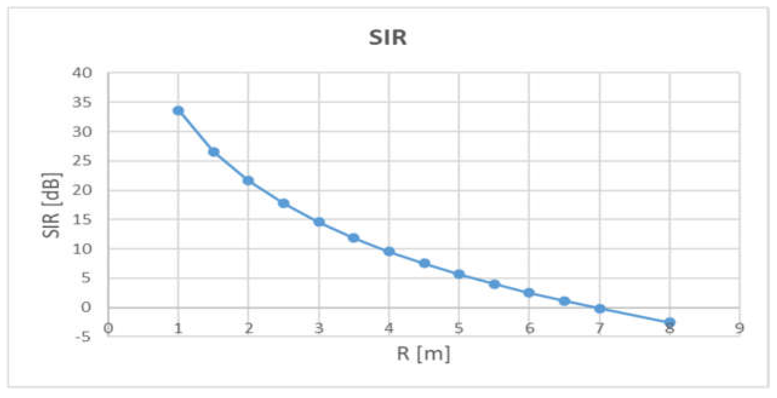
We calculated the SIR for different distances between 1 and 8 m and determined the maximum efficiency of the jamming system (distance between the jamming equipment and the Digi Mobile smartphone), which corresponded to the case when SIR = 0 dB.
Figure 6 presents the decreasing SIR according to the increasing distance between the system jamming and the smartphone.
If we modified the system such that
, all SIR values calculated and presented in
Table 3 would be half of the values presented.
If we considered the maximum
and
, the values calculated and presented in
Table 3 would be a quarter of the SIR values presented.
To perform a denial of service (DoS) through jamming, it is enough to block only one connection of the mobile terminals, i.e., the downlink or uplink. To jam downlink connections, several conditions must be fulfilled, including completing a study of the availability of the network providers and the radio environment must be suitable for this kind of jamming.
Even for academic purposes, jamming uplink connections is illegal, and thus, these kinds of simulations were excluded because the jamming device would introduce dangerous interferences in the mobile operator network.
In Digi Mobil in laboratory conditions, jamming the downlink connection was successful since the strength of the network parameters did not exceed the possibilities of the Hack-RF in terms of power. The method of jamming the whole downlink band was shown not to be a reliable one because it depended very much on the network provider emitting signals and, of course, on the limited power and bandwidth of Hack-RF.
After conducting the tests on downlink jamming, with all the constraints mentioned above, our efforts were concentrated on developing an intelligent jamming system for the downlink connection. This system aimed to block the access of smartphones from registering in the network by employing pulsatory jamming in the downlink bands that was triggered by the detection of data traffic in uplink bands. Very good results were obtained with this method of concentrating all the power only on the frequencies that carried traffic.
4. Experimental Setup and Results
In our experimental study for an intelligent jamming system, we used several tools to show the efficiency of the denial-of-service attack, including the following:
Nestor software by Rohde & Schwarz and TSMA 6 [
13].
Portable receiver PR 100 [
17].
A smartphone using QualiPock software and registered with Digi Mobil Romania.
Laptop with OS Kali Linux.
Hack-RF SDR with the following specifications [
18]:
- ⮚
Frequency range = 1–6000 MHz.
- ⮚
Half duplex.
- ⮚
ADC resolution = 8 bit.
- ⮚
Bandwidth = 20 MHz.
Directional antenna adapted to mobile communication frequency ranges.
Python code.
4.1. Initial Measurements
The first scenario was when the receiver was located near the cell.
Figure 6 displays the received signal level measured for a downlink frequency of 793.5 MHz. The level of signal received was −76.8 dBm, which corresponded to the proximity of the cell’s base station. Additionally,
Figure 7 shows the resource block measured on the central frequency of 793.5 MHz with a bandwidth of 5 MHz.
By applying Formula (6), the path loss was calculated at a 1 m distance as being −33.238 dBm. Subsequently, using Formula (7) with the received signal level (RSRP) of −79.5 dBm, we determined a signal-to-interference ratio (SIR) of −33.63. This calculation indicates that jamming the downlink connection in the condition of good signal strength was confirmed by the experiment.
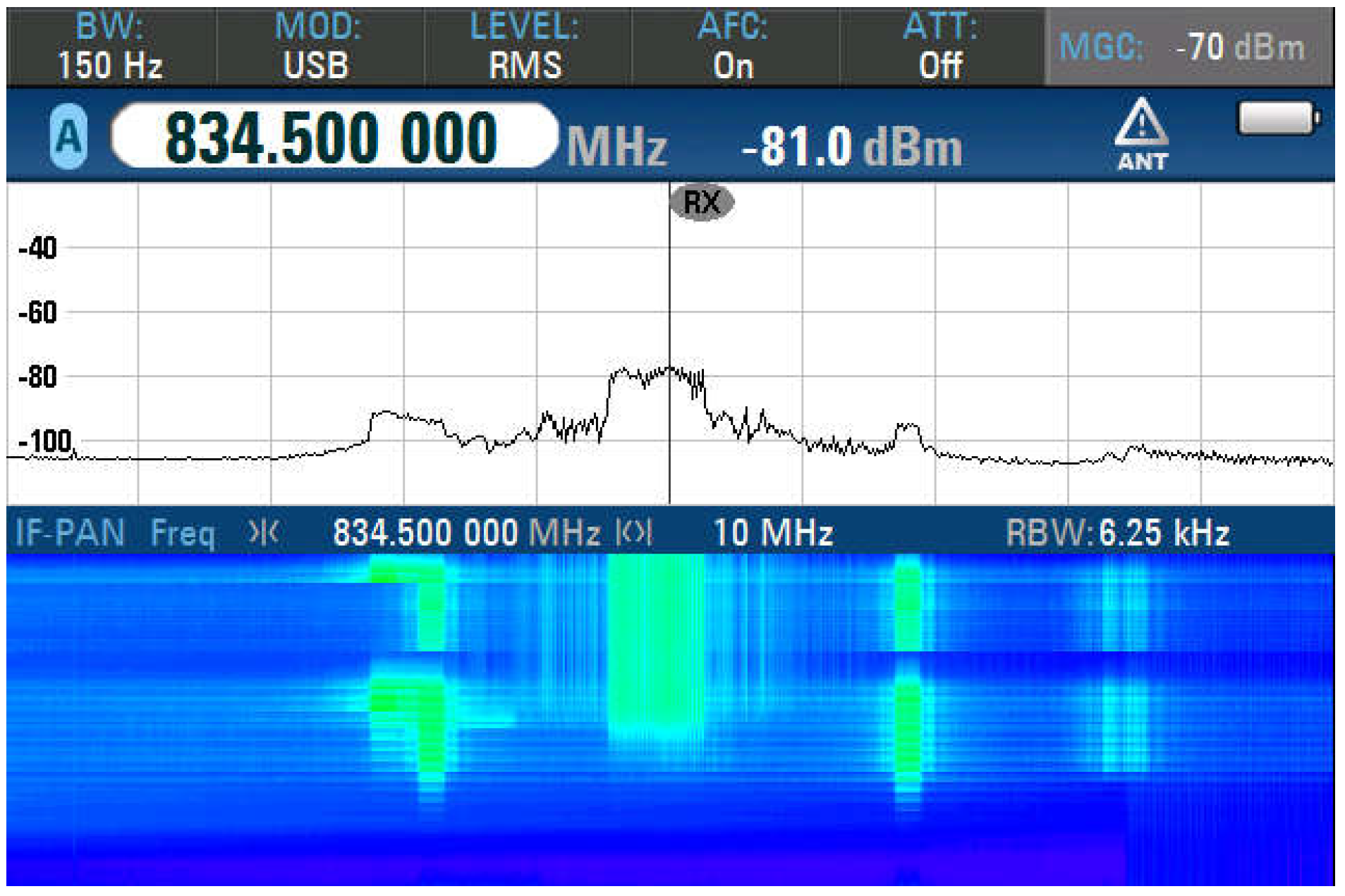
Figure 8 presents the signal level measured on the uplink connection corresponding to an uplink frequency of 834.5 MHz, which was measured at −81 dBm; this is illustrated in green in the waterfall window and corresponds to the vicinity of the cell. We could conclude that the smartphone that was next to the cell emitted less power at the uplink frequency thanks to the signalling procedure in which the smartphone revealed its location in the network. As a result, the power level was adjusted, considering the network, to be lower.
Figure 9 presents the received signal level measured for a downlink frequency of 793.5 MHz, which was measured at −94.1 dBm and corresponded to the edge of the cell coverage. It is shown in
Figure 9 that the resource block measured on the central frequency was 793.5 MHz with a bandwidth of 5 MHz. Applying Formula (6), the path loss
was calculated at a 1 m distance to be 3−3.238 dBm, and the SIR, which was calculated with Formula (7) for the signal level of the RSRP of −94.1 dBm, was −19.514. The value of the SIR was below the minimal value of the limits presented above for an LTE connection. Therefore, jamming in this condition can successfully affect the communication channel.
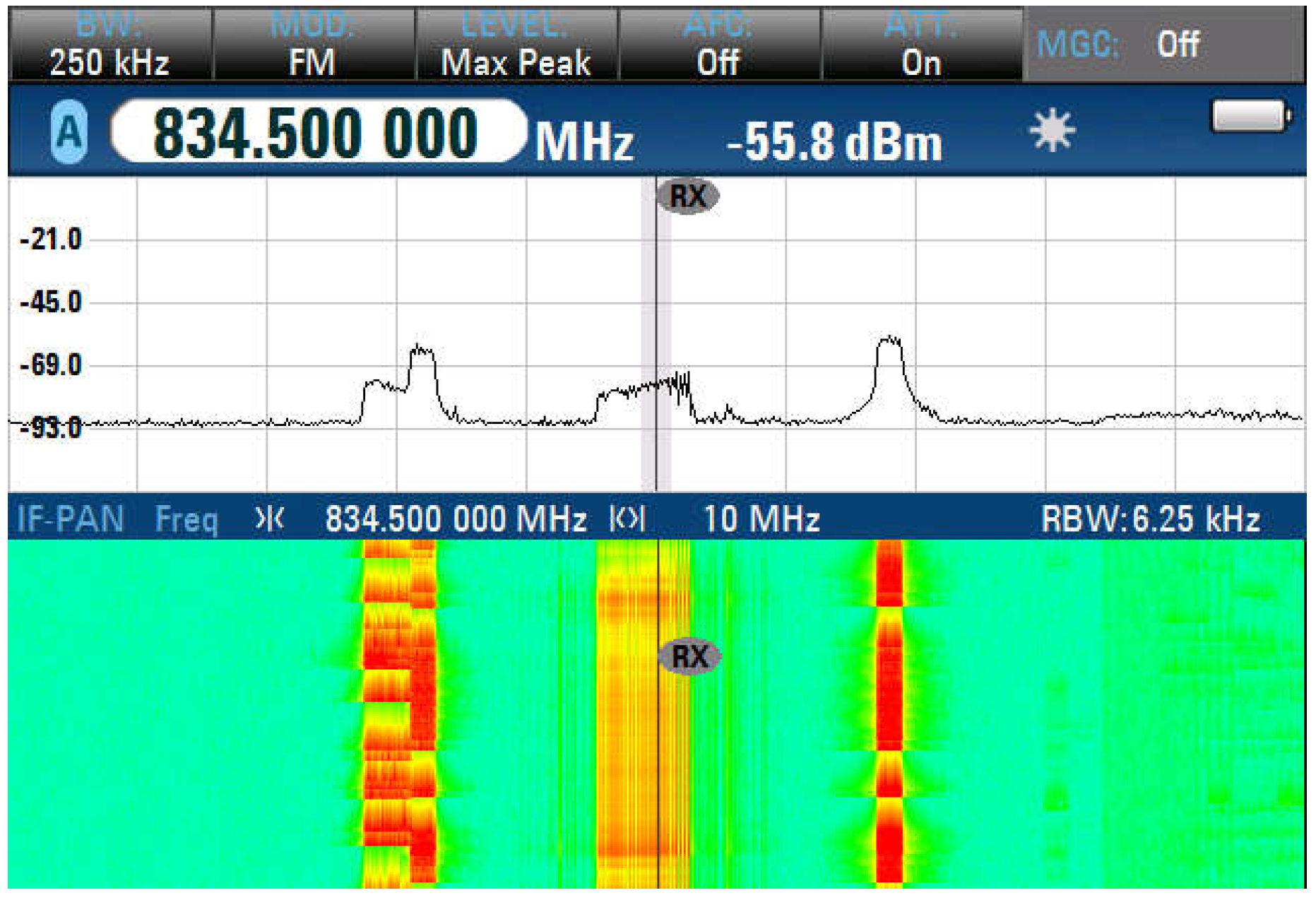
Figure 10 presents the signal level measured on an uplink connection corresponding to the uplink frequency of 834.5 MHz, which was measured at −55.8 dBm when the smartphone was transmitting to the network in a data session. We could conclude that a smartphone that was at the edge of the cell emitted more power at the uplink frequency because of the signalling procedure in which the smartphone revealed its location in the network, and thus, the power level was increased in accordance with the network.
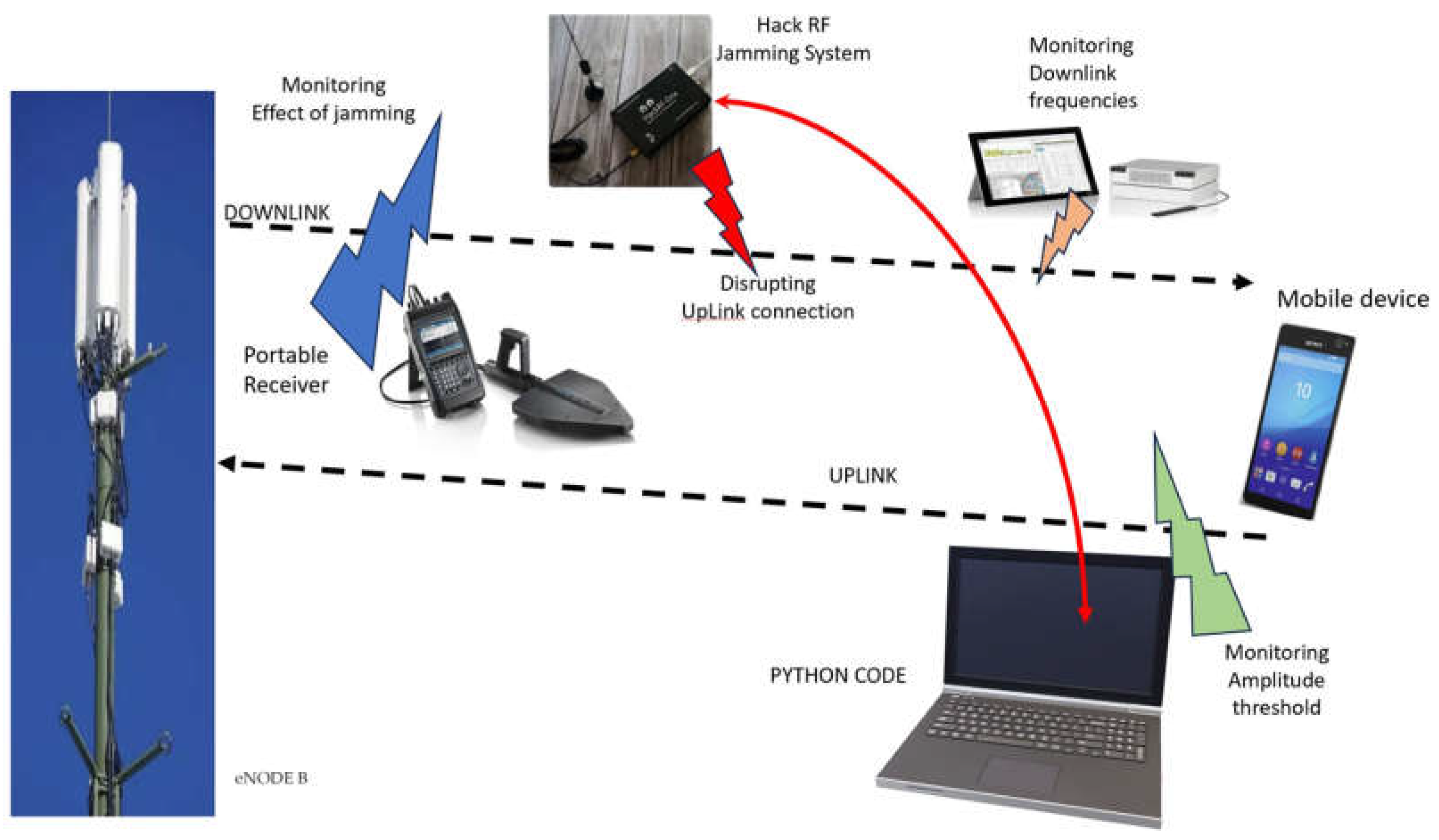
Figure 11 illustrates the setup used for the experimental jamming on the downlink connection in the real case scenario (Digi Mobil smartphone presented in
Figure 6), where the RSRP was −79.5 dBm. A radio monitoring spectrum analyser Nestor TSMA 6 was used to discover and measure all available frequency bands and the technologies provided at the radio-monitoring point. A list of all available frequencies was obtained and provided to the Hack-RF to prepare the jamming frequencies.
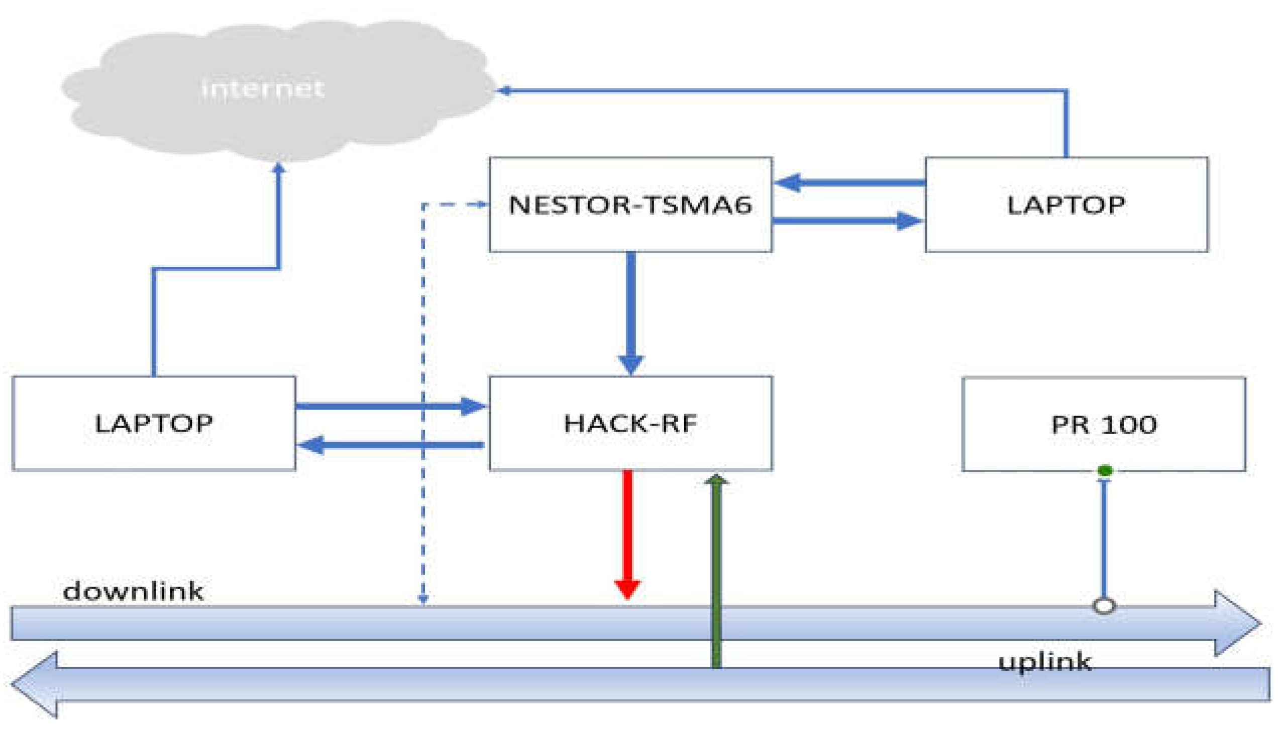
4.2. Implementation of the Jammer
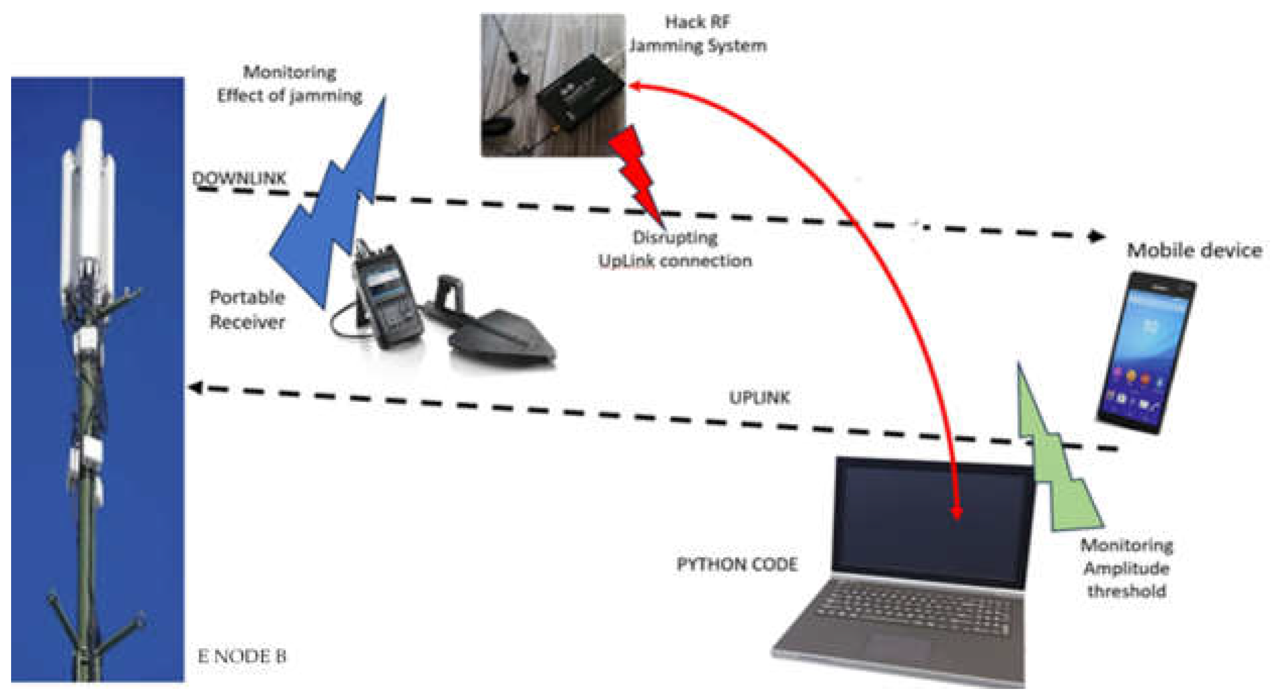
Figure 12 illustrates the block diagram of the experimental setup and the flow of data. It is shown that the spectrum analyser Nestor monitored the downlink connection and provided the laptop with all the measurements set by the operator. Through the internet, the list of downlink frequencies and channels with the received signal level was provided to the laptop that controlled Hack-RF. To perform a jamming attack, the operator of the jammer manually set the central frequencies of the downlink connections and the bandwidth. After all these parameters were set, jamming could be performed. PR100 confirmed the actual signal level and whether the jamming procedure affected the radio spectrum monitored.
The objective of jamming the downlink connection as shown in
Figure 13 was accomplished. It was shown that an emission next to the receiver interfered with the downlink and disrupted the communication between the network and the smartphone. Therefore, taking into consideration the Matlab-simulated scenarios, the jamming of the downlink was verified and demonstrated.
Monitoring the downlink frequencies can provide important information regarding the potential for employing reactive jamming on these frequencies. The efficiency of the jamming system was determined by monitoring the downlink by considering a Hack-RF output power of 15 dBm at its maximum, along with a 7 dBi antenna gain, resulting in a total of 22 dBm.
Once the downlink channels were identified with the Nestor monitoring spectrum analyser based on the frequencies, the uplink frequencies could be calculated for monitoring purposes. This allowed us to focus our monitoring efforts exclusively on these frequencies.
Basically, the block diagram and flows are illustrated in
Figure 14:
Practically, any amplitude detected on the uplink frequencies provided by Nestor above −70 dBm triggered an emission at the corresponding downlink frequency at the maximum Hack-RF power. Hack-RF was used for detection and emission. After 15 s, the jamming was stopped, and the process repeated in a loop.
The usage of jamming only of the existing downlink frequencies in the respective area offers the advantage of using reduced processing power, as well as a much shorter time to act [
19,
20].
A Python script was developed for an intelligent jamming system that uses Hack-RF and calls upon a set of standardised Hack-RF manipulation libraries. Practically, the entire uplink band of 800 MHz LTE technology was scanned. The next step involves scanning these uplink frequencies to see whether there are radio signals emitted by mobile phones [
12].
Figure 15 depicts the setup for the jamming downlink connection without using a spectrum analyser. As we can observe, the Python code acts directly on Hack-RF through the developed code.
Once the uplink frequency is identified, the entire scanning process stops following the jamming of the mobile phone. Stopping the scan and switching to emission brings a delay time to the whole process. This time cannot be 0 s because the SDR Hack-RF is not a full duplex; therefore, it cannot receive and emit concurrently, and thus, these processes must be independent in time.
To perform this test, a mobile phone registered on the Digi Mobil Romania network in the 800 MHz LTE technology was utilised and a voice call was made using this smartphone.
Considering the uplink frequency band and the 100 kHz channel splitting, a spectrum scan was performed using Python code on the uplink frequencies starting from 832 MHz up to 862 MHz. The first central frequency for LTE 800 was 834.5 MHz, channel 24,175; then, all central frequencies were scanned with a spacing of 100 kHz so that only the LTE 800 channels were considered [
21].
The Python script was used to process the data to identify and visualise the signals across various frequency bands, making it useful for tasks like frequency analysis, signal identification and identifying potential sources of interference.
After scanning, the maximum level of amplitude on the frequency of 834.5 MHz was identified. In our laboratory conditions, the smartphone registered in the LTE 800 MHz band, the UL measurement revealed that the smartphone amplitude in this conditions was almost −68.32 dBm [
22].
After identifying this frequency, Hack-RF was tuned to the identified frequency, enabling it to emit a stronger signal in terms of the amplitude and wider bandwidth in the waterfall window, as illustrated in
Figure 15. After 10 s, the jamming was stopped, and the scanning procedure started to identify another amplitude level above −60 dBm. The advantage of this method of scanning only a predefined list of frequencies lies in the fact that the spectrum will be swept much faster so that the chances of an illegal phone being able to access the services are very low. Another advantage is reflected in the use of receivers and transmitters whose band does not have to cover the entire spectrum. The main disadvantage of this method consists of the fact that the spectrum must be periodically scanned to identify the changes made by mobile phone operators in the area or to be aware of the implementation of new technologies. Even if it is necessary to periodically scan the radio spectrum from the point of interest, in practice, it is known that the network operators do not make changes every day in their allocation of technologies in frequency bands. This is why we include a table (
Table 1) displaying the leased bands authorised by the regulatory authority where Digi Mobil must provide services. As a result, the network operators cannot provide services in bands other than those assigned to them. In
Appendix A, we present the pseudocode behind the Python code developed.
The results were determined after the distance between the Hack-RF antenna and the smartphone was reduced. After several tries, it was determined that the effect of the jamming with the power provided by Hack-RF became noticeable at 1.5 m. At 8 m, the effect of the jamming was not as clearly visible in the radio spectrum.
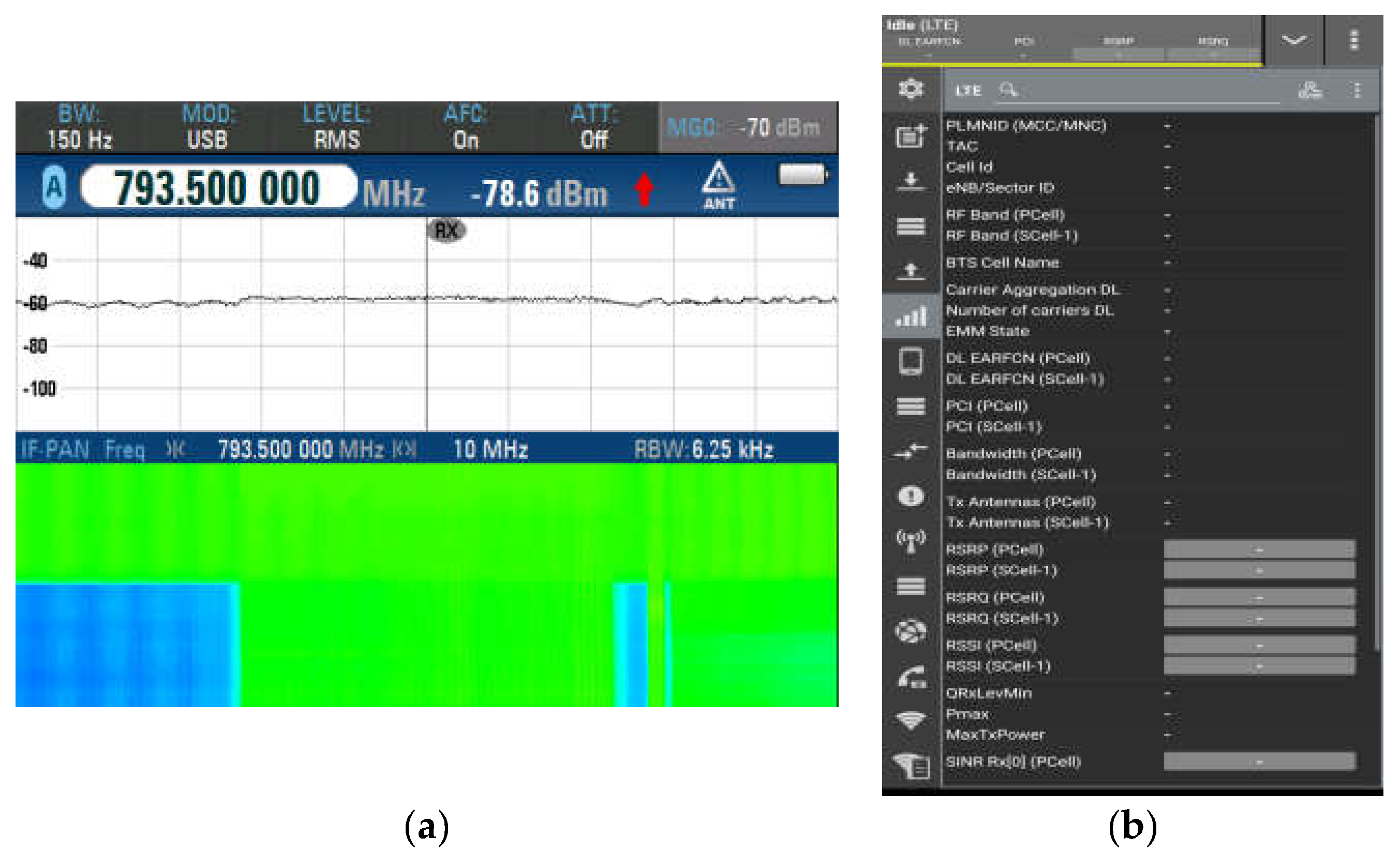
Figure 16a presents the radio spectrum obtained with PR100, which shows the manifestation of the jamming on the downlink frequency of 793.5 MHz.
Figure 16b presents the effect of the jamming device on the smartphone-received signal.
As demonstrated earlier, there are several methods for jamming smartphone network connections based on the characteristics of the network availability in the area and with some commercial tools available in online markets.
For a man-in-the-middle attack using denial of service, jamming devices are highly effective in indoor conditions. Therefore, an attack is most likely to occur indoors. To avoid such an attack, it is important to be careful with our smartphones, and when we notice any fluctuations in the received signal or vertical handover, it is recommended to use an application to monitor the cell parameters to discover whether it is an attack. If we discover that we are a victim of a denial-of-service attack, for our protection, it is advisable to manually activate airplane mode from the smartphone menu and leave the indoor area [
3].
Fortunately, this kind of denial of service attack does not compromise subscribers’ personal data or provide the ability to track their activities. However, it can affect the possibilities to communicate by altering the radio spectrum capabilities.
Unfortunately, if the denial-of-service attack is a success and the smartphone is registered as using GSM technology, which has known vulnerabilities, attackers with the right hardware and software may be able to perform other types of attacks, including identifying unique parameters like IM-SI/IMEI or more severe actions like eavesdropping or locating the subscriber within the network [
23,
24].
5. Discussion, Conclusions and Future Work
In this study, we investigated and developed an intelligent jamming system that works on fixed frequencies, specific technologies and downlink connections of mobile network operators.
Jamming is a process that is made intentionally by a malicious person or by a mistake produced due to an equipment fault. Intentional jamming can alter the performance of the radio mobile connections, introducing the possibility of developing other types of attacks that are more destructive, with a lot of consequences for the personal data of the subscribers.
After conducting our experiments, we could conclude that an attacker can carry out a denial-of-service attack on the downlink connection with commercial instruments at accessible prices. According to our proposed objectives mentioned above, we could conclude the following.
For the first objective, we determined that in the case of jamming the downlink connection, it was difficult to obtain 100% jamming results. The condition of jamming depends very much on the strength of the receiving signal level from the network operators who provide services, as measured at the radio-monitored point of interest. The limitations also encompassed the limited jamming range for smartphones. The jamming effect was only pronounced at distances of less than 8 m without any obstacles.
The evaluation of the second objective brought to light that a study is required regarding the downlink frequencies available and, based on this, to calculate the uplink frequencies. Experiments were conducted to demonstrate that the feasibility of employing reactive jamming on a downlink connection hinged on a technical constraint.
The last objective was achieved successfully. We developed, tested and demonstrated that an intelligent jamming system that works completely autonomously in a specific indoor area could disrupt the downlink connection based on the detection of an uplink. A new Python script was developed.
The intelligent jamming solution presented in this paper has its technical limitations. The configuration of the hardware platform is not a compact one: it has individual equipment and antennas, which makes installation on site more difficult. The maximum transmitting power of the Hack-RF SDR equipment is only 22 dBm (158 mW). This limits the coverage area of the jamming; thus, for larger areas, is necessary to use two or three such pieces of equipment, increasing the risk of intermodulation interference. A feasible measure to increase the range is to use a power RF amplifier installed at the Hack-RF SDR output.
With respect to the jamming technologies, there are no limitations; we can adapt this system for jamming 2G, 3G and of course 5GSA, but the 5GSA standard is not available in Romania yet. Limitations include the distance of the jamming effect and logistical limitations, including the disposal of the antennas, cable installation and minimal technical requirements to ensure a stable temperature for the entire system.
Regarding further studies, researchers can identify methods to monitor security attacks and the areas where they occur, the possibility to limit the access for sensitive information applications and extensions for other technologies available in IoT (like WiFi and BLE).


 ,
, 


