Abstract
It is known that a large amount of vibration mechanical energy will be generated during train operation. If the mechanical energy can be obtained from the track structure, it can greatly optimize the energy configuration of the metro. Currently, most sensors are limited to disk or cymbal structures and are not used in the track bed; different from existing structures, this paper designs a spherical energy harvester based on a rubber bearing floating slab track, wherein the size range of the spherical energy harvesting structure was approximately determined based on the geometric spatial relationships of the actual track bed internal structure. Compared to the traditional disk and cymbal energy harvesters, the mechanical and electrical properties of the spherical energy harvesting structure was studied by a numerical simulation method, and the optimal size of the spherical energy was determined by calculation. The main conclusions are as follows: (1) Compared with the traditional disk harvester and cymbal harvester, the spherical harvester had better mechanical and electrical properties. (2) By calculating the output power of energy harvesters under load matching, we found that the output power of the spherical harvester was two orders of magnitude higher than that of the disk harvester and 53% higher than that of the cymbal harvester. (3) The optimum size of the spherical harvester was when the thickness of piezoelectric layer was 2 mm, the radius was 16 mm, the axial ratio of the spherical shell was 0.4, and the thickness of the spherical shell was 4 mm.
1. Introduction
In recent years, urban rail transit has been widely accepted as a large-capacity and low-carbon transportation mode. With the increasing mileage of rail transit operation, its operational safety has been paid more and more attention [1]. To ensure the safety of rail transit during the operation period, it is necessary to carry out health monitoring on its engineering structure. Traditional monitoring sensor networks are mainly connected to a mains power supply or battery, which has some problems such as high maintenance cost and environmental pollution. Since a large amount of mechanical energy will be generated by train operation in urban rail transit system [2], it is of great significance to design a kind of energy harvester to capture electric energy from the track structure.
At present, many scholars have designed energy harvesters for rail transit infrastructure in order to capture energy from different structures and positions, mainly including rails, fasteners, and sleepers. For the rail, Li et al. [3] designed a broadband cantilever energy harvester, which installed a broadband piezoelectric array on one side of the rail to capture the track vibration mechanical energy during train operation at various frequencies. Due to the train vibration frequency deviating from its working frequency band in real environment, it did not achieve the expected effect. Zhang et al. [4] developed a portable and efficient electromagnetic energy harvesting system with supercapacitors, which was installed at the bottom of rails to convert the energy of track vibration into electric energy and provide stable power output for external loads. For the fastener, Yuan et al. [5] designed a piezoelectric energy harvester installed under the fastener backing plate to capture the energy generated by train vibration, and the power obtained was sufficient to power the wireless sensor. For the sleeper, Wang et al. [6] designed an energy harvester for the upper part of the sleeper based on the electromagnetic energy collection technology. It featured a gear structure that converted the irregular pulse bidirectional linear vibration of the track into adjustable unidirectional rotational motion to improve the output power and reliability. Lin et al. [7] also designed an enabling structure for the upper part of sleeper, using a spring pretensioning and resetting device for quick installation without anchoring it into the railroad foundation. In addition to the design of energy harvesters starting from common track infrastructure components, scholars have carried out corresponding energy capture research on floating slab track. Hou et al. [8] proposed a small but high bearing capacity piezoelectric energy harvester for steel spring floating slab track, which was mainly installed between track slab and steel spring supporting structure to improve the energy harvesting efficiency. At present, the design of energy harvesters for a floating slab track cannot cover all types, so it still needs further study.
The piezoelectric energy harvesting structure utilizes the positive piezoelectric effect of piezoelectric materials to convert mechanical energy into electrical energy [9], thus achieving energy recovery and reuse. The materials involved in piezoelectric energy harvesting mainly include piezoelectric ceramics (PZT), polyvinylidene fluoride (PVDF), and piezoelectric fibers. Piezoelectric materials, especially PZT, are generally not directly exposed to the working environment in the process of energy conversion due to their own brittleness, weak bearing capacity, small displacement, and other characteristic limitations, but packaging structures are added outside them to form piezoelectric energy harvesters [10]. At present, there are many studies on piezoelectric energy harvesters. The common energy harvesters are cantilever beam type [11,12,13,14,15], cymbal type [16,17,18], multilayer stack type [19,20], bridge type [21,22], arch type [23,24,25], etc., and there are new energy harvesters [26,27,28,29] 2,201,2424 made of composite materials, such as piezoelectric fiberboard (MFC), polyvinylidene fluoride (PVDF), and piezoelectric film.
The cymbal energy harvester is the earliest energy harvester designed and studied, and it is also recognized as energy harvester with comprehensive performance. It consists of metal caps at the upper and lower ends and piezoelectric layers in the middle, so it can capture radial and axial vibration energy at the same time and have high conversion efficiency. Kim et al. [30] tested the ability of a cymbal energy harvester to obtain electrical energy in a dynamic vibration environment, finding that metal end caps can increase ceramic endurance so that the whole structure can bear a higher load. Zhao et at. [31] used finite element software to analyze the geometrical parameters of cymbal energy harvesters applied to asphalt pavements, and the results showed that the energy harvesting efficiency was related to many factors, such as cymbal spacing, end cap thickness, and cavity height.
The improvement and application of the cymbal energy harvester structure has also been concerned by many researchers. Based on the traditional cymbal energy harvester, G. Yesner et al. [32] designed a bridge structure energy harvester with metal end caps and a new type of electrode. Compared with the traditional cymbal piezoelectric energy harvester, the energy obtained was increased, and the failure period was obtained by cyclic loading of the prepared structure. It was found that the inconsistent thickness of the bonding layer was the cause of the structure failure. Liu et al. [33] designed another radial layered cymbal piezoelectric energy harvester. To match the vibration frequency under traffic load, the metal end cap was calibrated by theoretical calculation and experimental test. The output power of the structure was not high, but a scheme to optimize the cymbal energy harvester structure was provided. The disadvantage of a cymbal piezoelectric energy harvester is that the metal end caps will cause stress concentration at the inner edge of ceramic plate, resulting in damage or fracture of the ceramic plate. In addition, the manufacturing process of a cymbal energy harvester is complex, and there are limitations in practical application.
The sensors mentioned in the current article are limited to disk or cymbal structure and not used in the track bed; different from existing structures, this paper designed a spherical energy harvester based on a rubber bearing floating slab track, and the size range of the spherical energy harvesting structure was approximately determined based on the geometric spatial relationships of the actual track bed internal structure. Compared to the traditional disk and cymbal energy harvester, the mechanical and electrical properties of the spherical energy harvesting structure were studied by the numerical simulation method. Meanwhile, in order to improve the energy harvesting efficiency of the spherical energy harvester, the geometric parameters such as piezoelectric layer thickness, piezoelectric layer radius, spherical shell axial ratio, and spherical shell thickness were analyzed to obtain the optimal geometric size.
The architecture of the paper is organized as follows: Section 2 introduces the spatial location where spherical sensors are suitable for harvesting energy in the track bed. Section 3 proposes the dimensions and parameters of spherical energy harvesting structure. Section 4 introduces the performance differences between the disk, cymbal, and spherical energy harvesting structure. Section 5 introduces the optimization process of geometric parameters of the spherical energy harvesting structure.
2. Energy Harvesting Position of Rubber Bearing Floating Slab Track
When the energy harvester is laid in urban rail transit, the existing research mainly focuses on the position close to the vibration source, such as rail and fastener, but it needs to occupy some bounded space, so its application scope will be limited in the rail transit operation environment with strict limit requirements. At the same time, there is a possibility of loosening and dropping of the installation under the long-term reciprocating train operation environment, which has certain potential safety hazards. Therefore, the designed energy harvester in this paper is considered to be arranged inside the floating slab track, thus reducing the impact on the safety of train operation. To make full use of the mechanical energy generated during train operation and realize large-scale power generation, energy harvesters are mainly in the form of an array. An array of energy harvesters is formed under each rubber support, and its position and arrangement are shown in Figure 1.
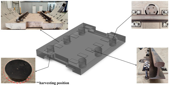
Figure 1.
Energy harvesting position.
3. Proposal of the Spherical Energy Harvester
The disk energy harvester is the simplest type, being mainly composed of the piezoelectric layer in the middle and force transmission structures at both ends. The piezoelectric layer is made of piezoelectric ceramic (PZT-5H), while the force transmission structure is made of steel, and they are both wafer-shaped. The geometric dimensions of the disk energy harvester are shown in Figure 2.
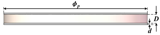
Figure 2.
Dimensions of the disk energy harvester.
Here, denotes the thickness of force transmission structures at both ends; indicates the thickness of the piezoelectric layer; and shows the diameter of the disk energy harvester.
The cymbal energy harvester is one kind of energy harvester with better performance, mainly consisting of the piezoelectric element and metal caps on both sides, which are generally bonded by epoxy resin or anchored by bolts. The material used is consistent with that of the disk energy harvester, that is, PZT-5H is used for piezoelectric elements, and steel is used for metal caps.
Due to the special structure of the metal cap, the axial load applied on the metal cap is converted and amplified into two components along the axial and radial directions of the piezoelectric layer, resulting in a larger voltage than that of the general disk energy harvester. The geometric dimensions of the cymbal energy harvester are shown in Figure 3 [31].
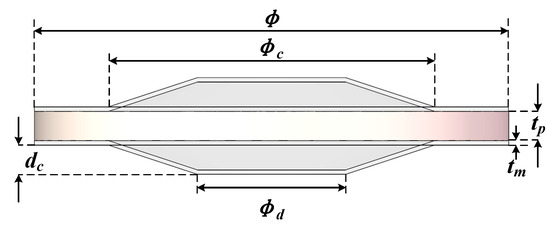
Figure 3.
Dimensions of the cymbal energy harvester.
Here, denotes the thickness of the metal cap; indicates the thickness of the piezoelectric layer; is the inner cavity bottom diameter; is the inner cavity top diameter; indicates the height of the inner cavity; and denotes the diameter of cymbal energy harvester.
The spherical energy harvester studied in this paper is composed of the piezoelectric layer and spherical shells at both ends. The piezoelectric layer is a circular sheet structure with a thickness of 2 mm and a diameter of 32 mm. The outer diameter of spherical shells at both ends is the same as that of piezoelectric layer, that is, 32 mm. The whole structure is shown in Figure 4. Similarly, the piezoelectric layer is made of PZT-5H, and the spherical shell is made of steel [34].
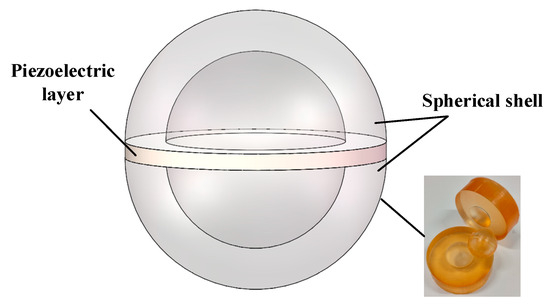
Figure 4.
Spherical harvester energy.
The material parameters of PZT-5H and steel used for each energy harvester are shown in Table 1 and Table 2 [8].

Table 1.
Material parameters of PZT-5H.
Table 2.
Material parameters of steel.
4. Performance Comparison of Energy Harvesters
4.1. Numerical Model
In the COMSOL Multiphysics software, the output voltage of each energy harvester was simulated by using the coupled physical field of solid mechanics and electrostatic. In order to simulate the voltage output characteristics of energy harvesters under the same stress state, energy harvesters of different structural types were embedded in the cylindrical concrete structure with a height of 50 mm and a diameter of 32 mm, where the concrete strength grade is C35. The overall model is shown in Figure 5.
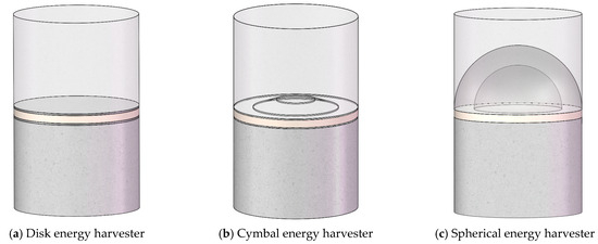
Figure 5.
Numerical model of energy harvesters.
After assigning each part to corresponding materials, a base vector coordinate system was defined so that the piezoelectric material was polarized along the direction of the load. A uniform load of 0.3 MPa was set at the top of the concrete column with the direction perpendicular to its upper surface, and a uniform circumferential pressure of 0.2 MPa was set. At the same time, fixed constraints were set at the bottom of concrete columns. The model set the ground boundary as the bottom of the piezoelectric layer, the terminal boundary as the top of the piezoelectric layer, and the terminal type as electric charge. The initial potential of the piezoelectric layer was 0, and the zero-charge boundary was set in the circumferential direction.
4.2. Mechanical and Electrical Performance
Since the electrical signal output from the energy harvester varies with excitation, an energy harvesting circuit is required to capture or store the electric energy generated by the structure [35,36]. While the energy harvesting circuit also has certain requirements for the output signal of the energy harvester, it generally requires the minimum output voltage of the energy harvester to be around 0.5~1.4 V. If the output voltage of the energy harvester is less than the minimum turn-on voltage, the circuit will be in an open circuit and will not be able to transmit or store electric energy. Therefore, the output voltage of the energy harvester is one important electrical characteristic.
As shown in Figure 6a, the stress of the disk energy harvester was concentrated at the force transmission plate, and the peak stress was 0.45 MPa. As shown in Figure 6b, the output voltage of the disk energy harvester had an obvious laminar distribution along the axial direction, and the maximum value was 0.62 V. The total electricity generated was calculated to be 1.09 × 10⁻⁹ J.
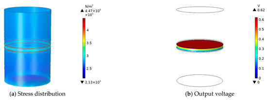
Figure 6.
Mechanical and electrical properties of disk energy harvester.
As shown in Figure 7a, the stresses in the cymbal energy harvester were concentrated at the top and bottom edges of metal caps with a peak stress of 3.62 MPa. As shown in Figure 7b, the output voltage of the cymbal energy harvester was obviously distributed in layers along the axial direction, and the maximum value was 6.5 V. The total electricity generated by this energy harvester was calculated to be 9.37 × 10⁻⁸ J.
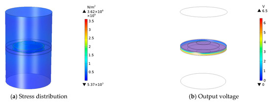
Figure 7.
Mechanical and electrical properties of the cymbal energy harvester.
Compared with the disk energy harvester, the output voltage and total output energy of the cymbal energy harvester were greatly increased. The output voltage was about 10 times higher than that of the disk energy harvester, and the total output energy was an order of magnitude higher than that of the disk energy harvester. However, the cymbal energy harvester showed a significant stress concentration at the change of geometric sizes, and the peak stress was about eight times higher than that of the disk energy harvester.
As shown in Figure 8a, the stress of the spherical energy harvester was concentrated at the bottom edge of the spherical shell, but there was an obvious uniform gradual change of stress along the surface of the spherical shell, thus effectively reducing the peak stress, which was 1.25 MPa. As shown in Figure 8b, the output voltage of the spherical energy harvester also showed obvious laminar distribution along the axial direction, and the maximum value was 6.7 V. The total electricity generated by the spherical energy harvester was calculated to be 1.17 × 10⁻⁷ J.
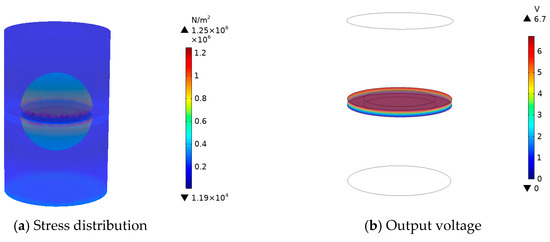
Figure 8.
Mechanical and electrical properties of the spherical energy harvester.
Compared with the disk energy harvester, the total output energy of the spherical energy harvester was greatly improved, being two orders of magnitude higher than that of the disk energy harvester. And compared with the cymbal energy harvester, although the spherical energy harvester also showed some stress concentration at the bottom of the spherical shell, the peak stress was reduced by 65% compared with the cymbal one due to the good stress homogeneity of the spherical shell structure. The spherical energy harvester had both good mechanical properties as well as superior electrical properties. Its output voltage was 11 times more than that of the disk energy harvester, and the total output electric energy was 20% more than that of the cymbal energy harvester.
4.3. Load Match
In general, the piezoelectric energy harvester can be equivalent to an AC power supply with internal resistance, and part of the generated electric energy was consumed by internal resistance, while the other part was used for the load resistor to do work. Therefore, for the piezoelectric energy harvester, load resistance matching is particularly important, and a suitable external load is beneficial to improve the output performance of the energy harvester. For the piezoelectric energy harvester, it is generally regarded as a sinusoidal alternating voltage source with constant amplitude, while for the piezoelectric material itself, it has capacitive and resistive properties. Figure 9 shows the equivalent circuit model of the piezoelectric energy harvester. Here, V is the voltage source; R0 is the equivalent internal resistor of the energy harvester; C0 is the equivalent capacitance; and RL is the load resistor.
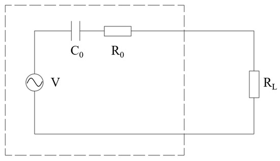
Figure 9.
Equivalent circuit of the energy harvester.
For the above equivalent circuit, the capacitance C0 is calculated as Equation (1):
where () represents the vacuum dielectric constant; denotes the relative dielectric constant; indicates the dielectric constant in F/m; is the piezoelectric layer area; and is the piezoelectric layer thickness.
The capacitive impedance , resistance , and the ratio of impedance to capacitive reactance is . PZTs are capacitive elements, and the capacitive reactance is far greater than the impedance, so the impedance of PZT can generally be ignored and regarded as a pure capacitive element. Therefore, the general value of is very small and negligible, and the load voltage is
Since the voltage source is a sinusoidal AC voltage, the load power is
From Equation (3), the output power is maximum when the external load resistance is equal to the internal impedance . The value of the load impedance at this time is called the matching impedance, that is,
Therefore, the matching impedance is not only related to the capacitance value of the piezoelectric energy harvester, but also related to the excitation frequency. The output power when the load is matched is
The load match model of disk energy harvester is established in COMSOL. In the global definition, the load resistance “” is defined, and the resistor is added with the resistance value “”, that is, the load resistor is set between the output end of the piezoelectric energy harvester and the ground node of the circuit. After setting up, frequency domain analysis can be used to study the effect of external load resistance on the output power of piezoelectric energy harvester, and the output excitation frequency used was 200 Hz. The voltage on the load resistor varied with the resistance, as shown in Figure 10a, and the power varied with the resistor, as shown in Figure 10b.
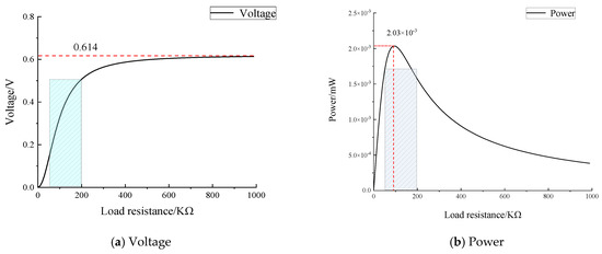
Figure 10.
Influence of load resistance on the electrical output characteristics of the disk energy harvester.
From the results, it can be seen that as the circuit load resistance increased, the output voltage increased monotonically and the rate of increase (i.e., the slope of the curve) decreased. When the load resistance increased to a near open circuit, the output voltage was 0.61 V, which approached the open circuit voltage of 0.62 V, and the curve tended to be flat. While the output power was low when the load resistance was very small or very large, it first increased and then decreased with the increase in the load resistance, and there was a maximum value. In addition, as can be seen from the shaded part under the curve, when the load resistance was in a certain range (50~200), the output power of the disk energy harvester was about 1.7 × 10⁻³ mW, which was at a low level. And the output voltage was less than 0.5 V in this resistance range, making it difficult to achieve the minimum input requirements of the energy capture circuit, so the electrical output performance of the disk energy harvester was found to be relatively ordinary. In this range, the load resistance that made the output power optimal was the “matching impedance”. Therefore, when , the maximum output power was 2.03 × 10⁻³ mW, and the internal resistance of the piezoelectric energy harvester was calculated to be 90.
The load match model of the cymbal energy harvester was established, and the effect of external load resistance on the output power of the cymbal energy harvester was studied by frequency domain analysis. The results of voltage variation with resistance on the load resistor are shown in Figure 11a, and the results of power variation with resistance are shown in Figure 11b.
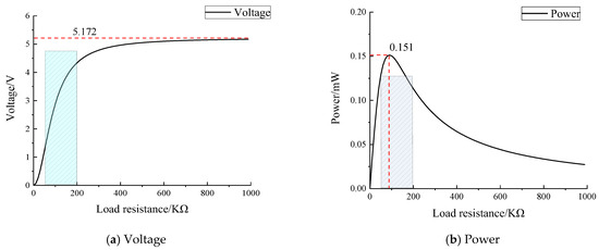
Figure 11.
Influence of load resistance on the electrical output characteristics of the cymbal energy harvester.
According to the results, as the circuit load resistance increased, the voltage across the resistor increased monotonically and at a decreasing rate. When the load resistance increased to a near open circuit, the output voltage was 5.2 V, which approached the open circuit voltage of 6.5 V, and the curve tended to flatten out. While the output power was low when the load resistance was very small or very large, it first increased and then decreased with the increase in the load resistance, and there was a maximum value in the process. When the load resistance was within a certain range (50~200), the output voltage of the cymbal energy harvester was able to reach the input requirement of the energy harvesting circuit, which was greater than 1.4 V. And the output power reached a high level, up to 0.13 mW. Meanwhile, when , the maximum output power was 0.15 mW, and the internal resistance of the cymbal piezoelectric energy harvester was calculated to be 90.
Compared with the disk energy harvester, the cymbal energy harvester had the same matching impedance of 90. But the output power of the cymbal energy harvester was two orders of magnitude higher than that of the disk type at a better load resistance, and it was up to the microwatt level.
The load match model of the spherical energy harvester was established, and the effect of external load resistance on the output power of the energy harvester was studied through frequency domain analysis. The voltage on the load resistor varied with the resistance, as shown in Figure 12a, and the power varied with the resistance, as shown in Figure 12b.
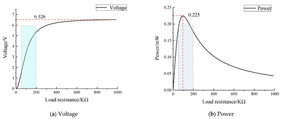
Figure 12.
Influence of load resistance on the electrical output characteristics of the spherical energy harvester.
As can be seen from Figure 12, with the increase in circuit load resistance, the voltage across the resistor increased monotonously, and the growth rate decreased. When the load resistance increased to a near open circuit, the output voltage was 6.53 V, which approached the open circuit voltage of 6.7 V, and the curve tended to level off at this time. The output power was lower when the load resistance was very small or very large, and the law was consistent with other energy harvesters, that is, the power first increased and then decreased with the increase in load resistance, and there was a maximum value in the process.
In addition, it can be seen from the shaded part under the curve that when the load resistance was within a certain range (50~200), the output voltage of the energy harvester was greater than 1.4 V, being able to meet the input requirements of the energy harvesting circuit. And the output power was able to reach a high level, up to 0.2 mW. When , the maximum output power was 0.23 mW, and the internal resistance of the spherical piezoelectric energy harvester was calculated to be 100 .
Compared with the disk and cymbal energy harvester, the matching impedance of the spherical energy harvester was slightly larger than the other two, at 100 . At the better load resistance, the output power of the spherical energy harvester was two orders of magnitude higher than that of the disk one and 53% higher than that of the cymbal energy harvester, which was also able to reach the microwatt level.
The output electrical properties of the three energy harvesting structures was as shown in Table 3.
Table 3.
Comparison of electrical properties.
The same load of 0.3 MPa was applied to the disk, cymbal, and spherical energy harvesting structures, and the power output efficiencies were 2.03 × 10⁻³ mW, 0.15 mW, and 0.23 mW, respectively.
In terms of the three types of energy harvesting structures, the disk energy harvester is simple in structure, easy to make, and long in service, but its energy harvesting efficiency is low. The energy harvesting efficiency of the cymbal type is higher than that of the disk type, but due to its complex structure, it can easily produce stress concentration, which is not conducive to long-term service. Compared with the disk energy harvesting structure, the output of the spherical energy harvesting structure is greatly improved. Compared with the cymbal energy harvesting structure, although the spherical energy harvesting structure also has a certain stress concentration phenomenon at the bottom of the spherical shell, the stress concentration phenomenon is weakened due to the good stress equalization of the spherical shell structure. Therefore, the spherical energy harvesting structure not only has good mechanical properties, but also has better electrical properties.
5. Parameter Optimization Design
5.1. Parameter Analysis
To investigate the optimal size of the spherical energy harvester, the parameter analysis of its geometry was carried out to obtain the optimal energy harvesting effect. The parametric geometry is shown in Figure 13.
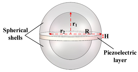
Figure 13.
Geometric model of the spherical energy harvester.
Here, H represents the thickness of the piezoelectric layer, R represents the radius of the piezoelectric layer, r1 represents the vertical axis radius of the inner cavity of the spherical shell, and r2 represents the horizontal axis radius of the inner cavity of the spherical shell. The outer radius of the spherical shell is aligned with the radius of the piezoelectric layer. The axis ratio I is defined as I = r1/r2, which is used to characterize the ellipticity of the hollow shell; the thickness of the spherical shell is T = R-r2. The parameters of the initial spherical energy harvester are shown in Table 4.
Table 4.
Initial size parameters.
To obtain the optimal size of the spherical harvester, the dimensions of the piezoelectric layer and hollow shell were parametrically analyzed, and the parameters mainly included the piezoelectric layer thickness H, the piezoelectric layer radius R, the axis ratio I, and the spherical shell thickness T. The material properties of each working condition were consistent during the analysis, and PZT-5H was used for the piezoelectric layer.
5.2. Piezoelectric Layer Thickness
The parametric numerical model of the spherical energy harvester was established according to the initial size, and the parametric scanning was defined. Thickness H scanning range was 0.5~8 mm, defined H = range (0.5, 0.5, 8). The peak stress, peak vertical displacement, peak voltage, and total electricity of the spherical energy harvester with different piezoelectric layer thicknesses were obtained.
The peak stress under different piezoelectric layer thicknesses is shown in Figure 14. The peak stress increased with the thickness of the piezoelectric layer, and the overall curve showed an increasing trend, although there were small fluctuations at some thickness values. With the increase in piezoelectric layer thickness H from 0.5 mm to 8 mm, the peak stress of the energy harvester increased from 1.3 MPa to 1.56 MPa, and the whole increase was 20%. Figure 15 shows the peak vertical displacement under different piezoelectric layer thicknesses. The peak vertical displacement decreased with the increase in piezoelectric layer thickness, and the decreasing trend was basically linear. When the thickness of the piezoelectric layer increased, the peak value of vertical displacement decreased from 2.47 × 10⁻⁴ mm to 2.29 × 10⁻⁴ mm, with a decrease of 7.3%.
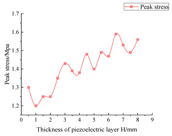
Figure 14.
Peak stress under different piezoelectric layer thicknesses.
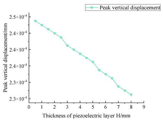
Figure 15.
Peak vertical displacement under different piezoelectric layer thicknesses.
As can be seen from Figure 16, the peak voltage increased with the increase in piezoelectric layer thickness, being almost linear as a whole. The peak voltage of the energy harvester increased from 1.6 V to 20.8 V, with a total rise of 13 times. Figure 17 shows the change of total electricity with the increase in piezoelectric layer thickness. It can be seen that the total electricity increased with the increase in piezoelectric layer thickness, and it increased from 2.66 × 10⁻⁸ J to 3.10 × 10⁻⁷ J, with an increase of 11.7 times.
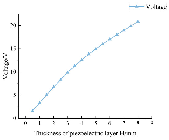
Figure 16.
Peak voltage under different piezoelectric layer thicknesses.
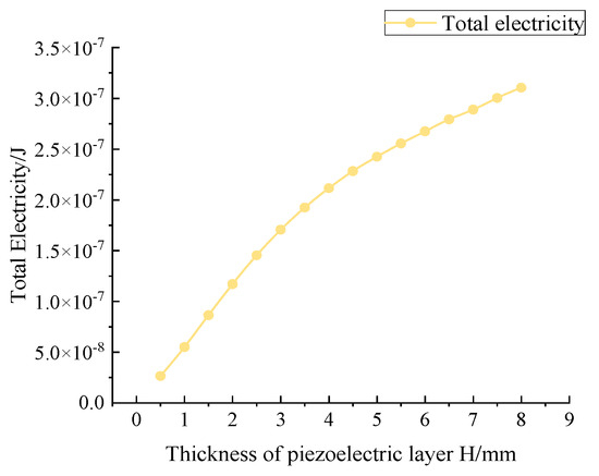
Figure 17.
Total electricity under different piezoelectric layer thicknesses.
Considering that the thickness of the piezoelectric layer exceeded 7 mm, the processing cost increased sharply and the material stability became poor. As can be obtained from Equation (1), with the increase in thickness, the capacitance C0 decreased, which was not conducive to matching with the load capacitance C1, resulting in low output efficiency when containing an external circuit. Therefore, the thickness of the piezoelectric layer should not be too thick, and if it is too thin, the total electric output will be too small. The minimum total electrical energy output was taken as a 1 × 10⁻⁷ J order of magnitude, and the minimum thickness of the piezoelectric layer under the electric energy output of this order of magnitude was 2 mm, so the optimal thickness of the piezoelectric layer was selected as 2 mm comprehensively.
5.3. Piezoelectric Layer Radius
In the study of the effect of piezoelectric layer radius on the energy-harvesting structure, parametric scanning was defined for the numerical model. The radius R scan range was from 6 to 23 mm, and R = range (6, 1, 23) was defined in the parameter value list. The peak stress, peak vertical displacement, peak voltage, and total electricity of the spherical energy harvester under different piezoelectric layer radii were also obtained.
The peak stress under different piezoelectric layer radii is shown in Figure 18, and the peak stress increased with the increase in the piezoelectric layer radius. The radius R of the piezoelectric layer increased from 6 mm to 23 mm, and the peak stress of the energy harvester increased from 1.02 MPa to 1.57 MPa, with an increase of 53.9%. Figure 19 shows the variation of the peak vertical displacement, which decreased and then increased with the radius of the piezoelectric layer. The minimum displacement value existed when the radius was between 18 and 21 mm, which was 2.41 × 10⁻⁴ mm. With the change of the piezoelectric layer radius, the peak vertical displacement decreased from 2.87 × 10⁻⁴ mm to 2.43 × 10⁻⁴ mm in general, which was a decrease of 15.5%.
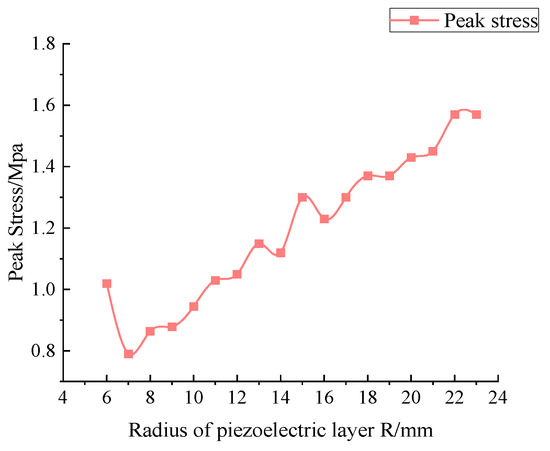
Figure 18.
Peak stress under different piezoelectric layer radii.
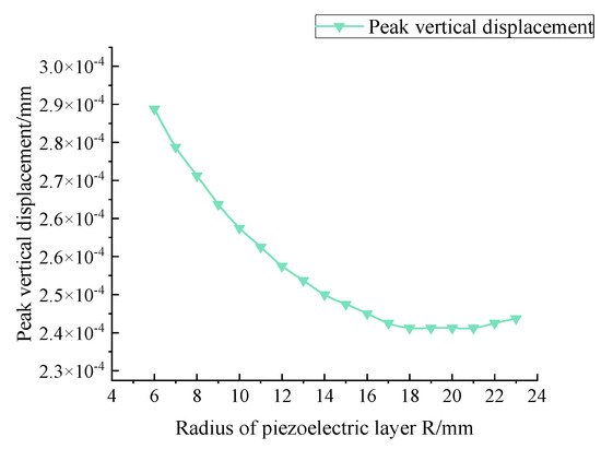
Figure 19.
Peak vertical displacement under different piezoelectric layer radii.
As can be seen from Figure 20, the peak voltage increased with the increase in the piezoelectric layer radius and then decreased, and the maximum value was 6.7 V when the piezoelectric layer radius R = 16 mm. With the increase in radius, the peak voltage of the energy harvester increased from 5.6 V to 6.5 V, which was 16% higher. The change of total electricity is shown in Figure 21. It can be seen that the total electricity increased with the increase in the piezoelectric layer radius, and it increased from 1.13 × 10⁻⁸ J to 2.3 × 10⁻⁷ J with the increase in the piezoelectric layer radius R from 6 mm to 23 mm, with a total increase of 20.4 times.
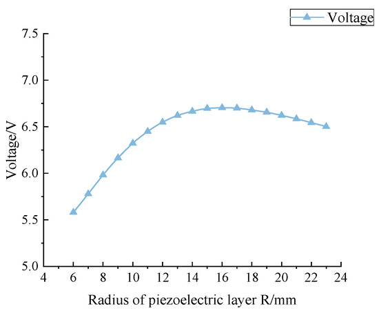
Figure 20.
Voltage under different piezoelectric layer radii.
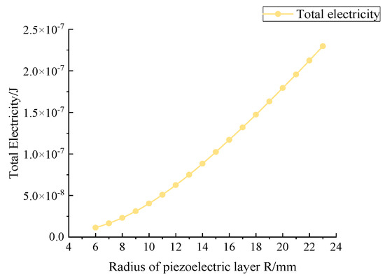
Figure 21.
Total electricity under different piezoelectric layer radii.
When the radius of piezoelectric layer varied from 6 mm to 23 mm, the peak stress and vertical displacement were within the safety range, so the electrical properties were given priority to determine the radius size. When the radius of the piezoelectric layer R was 16 mm, the peak voltage of the energy harvester can be taken to the maximum value of 6.7 V, and the minimum output voltage requirement (0.4~1.5 V) can be met. At this time, the total electricity was 1.17 × 10⁻⁷ J, so the optimal radius of piezoelectric layer was 16 mm.
5.4. Axial Ratio of Spherical Shell
When studying the effect of the axial ratio of the spherical shell on the energy harvester, the vertical axis radius of the inner cavity of the spherical shell should be kept consistent, at 11 mm. Because I = r1/r2, the axial ratio can be controlled by changing the radius r2. In the numerical model, R2 was defined as a parametric scan with a range of 5~30 mm, and R2 = range (5, 1, 30) was defined in the parameter value list. A simple calculation shows that the corresponding axial ratio range was 0.37~2.20. As the axis ratio increased, the geometry of the spherical shell slowly changed from a flat ellipsoid to a hanging ellipsoid. The stress nephogram of the spherical energy harvester with different axial ratios obtained by the COMSOL simulation is shown in Figure 22.
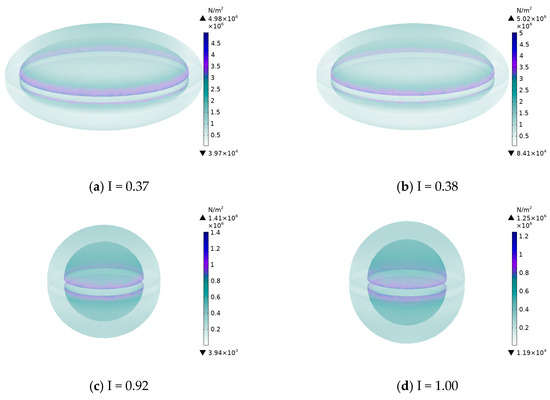
Figure 22.
Stress nephogram of the spherical energy harvester with different axial ratios.
Meanwhile, the peak stress, peak vertical displacement, peak voltage, and total electricity of the spherical energy harvester under different axial ratios of the spherical shell were obtained, as shown in Figure 23, Figure 24, Figure 25 and Figure 26.
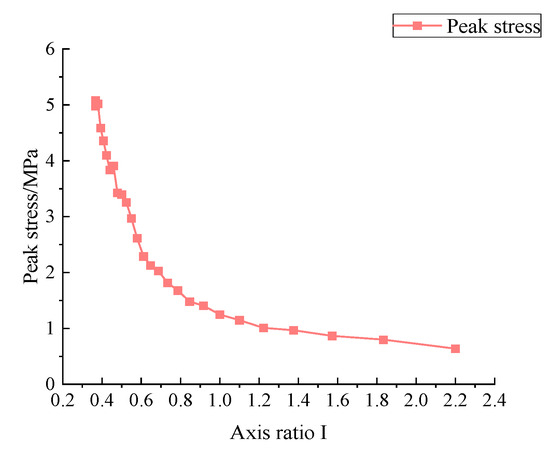
Figure 23.
Peak stress under different axial ratios of the spherical shell.
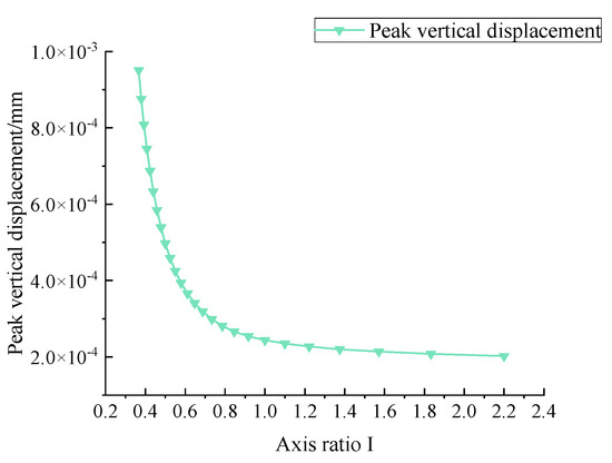
Figure 24.
Peak vertical displacement under different axial ratios of the spherical shell.
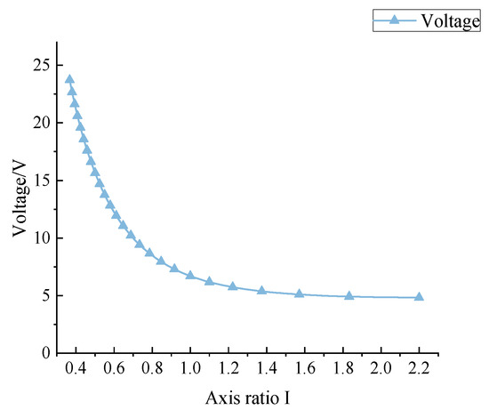
Figure 25.
Peak voltage under different axial ratios of the spherical shell.
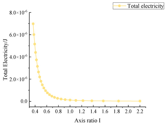
Figure 26.
Total electricity under different axial ratios of the spherical shell.
As shown in Figure 23, the peak stress decreased with the increase in the axial ratio of the spherical shell, and the decreasing rate became slower and slower. When the axial ratio of the spherical shell increased from 0.37 to 2.2, the peak stress of the energy harvester decreased from 5.08 MPa to 0.64 MPa, with a decrease of 87.4%. Figure 24 shows the variation of the peak vertical displacement, which decreased with the increase in the axial ratio of the spherical shell, and the decreasing rate also became slower and slower. With the increase in the axial ratio of the spherical shell, the peak vertical displacement decreased from 9.51 × 10⁻⁴ mm to 2.02 × 10⁻⁴ mm, a decrease by 78.8%.
As can be seen from Figure 25, the peak voltage of the energy harvester decreased with the increase in the axial ratio, and the decreasing rate slowed down continuously. The overall peak voltage of the energy harvester decreased from 23.7 V to 4.8 V, with the decrease of 79.8%. As shown in Figure 26, the change of total electricity decreased with the increase in the axis ratio, from 6.98 × 10⁻⁶ J to 2.35 × 10⁻⁸ J, which was two orders of magnitude lower. The variation of the peak voltage with the axial ratio of the spherical shell was analyzed, and it was concluded that the axial ratio of the spherical shell had a great influence on the electrical properties of the spherical energy harvester.
When the axial ratio of the spherical shell varied from 0.37 to 2.2, the peak stress and vertical displacement of the energy harvester were within the safe range. And the electrical properties such as peak voltage and total electricity changed obviously with the axial ratio, so the electrical properties were given priority to determine the axial ratio of the spherical shell. When the axial ratio of the spherical shell was small, the voltage and electric energy output of the energy harvester became better. That is, when the geometric design of the energy harvester was more inclined to the flat ellipsoid, it had better captive performance. When the axial ratio I was 0.4, the peak voltage was 20.6 V, which met the minimum output voltage requirement (0.4~1.5 V). And the total power was 4.40 × 10⁻⁶ J, which was at a better level. Therefore, the optimal axial ratio of the spherical shell was 0.4.
5.5. Spherical Shell Thickness
When studying the influence of the spherical shell thickness on the energy harvester, the horizontal axis radius of the inner cavity of the spherical shell was kept constant, at 11 mm. The axial ratio was controlled by changing the outer radius of spherical shell, i.e., the piezoelectric layer radius R. In the parameter value list, R = range (12, 1, 23) was defined, and the spherical shell thickness T = R-r2 ranged from 1 mm to 12 mm. The peak stress, peak vertical displacement, peak voltage, and total electricity of the spherical energy harvester with different spherical shell thicknesses were obtained.
As shown in Figure 27, the peak stress decreased with increasing spherical shell thickness. The spherical shell thickness T increased from 1 mm to 12 mm, and the peak stress of the energy harvester decreased from 4.28 MPa to 0.81 MPa, with a decrease in 81.1%. Figure 28 shows the variation of the peak vertical displacement, which decreased with increasing spherical shell thickness from 4.22 × 10⁻⁴ mm to 1.65 × 10⁻⁴ mm, with a decrease of 60.9%.
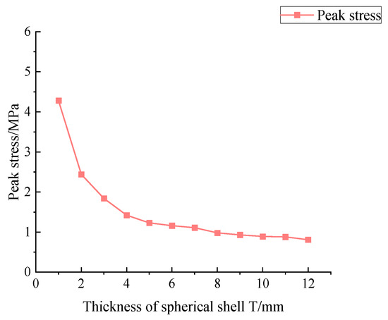
Figure 27.
Peak stress under different spherical shell thicknesses.
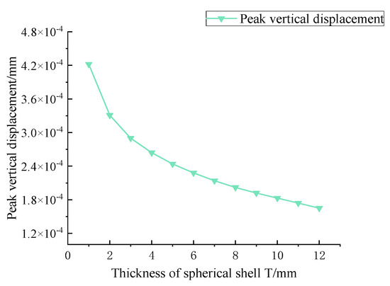
Figure 28.
Peak vertical displacement under different spherical shell thicknesses.
As can be seen from Figure 29, the peak voltage first increased and then decreased when the spherical shell thickness was continuously increased, and the peak voltage was 6.7 V when the thickness T = 4 mm. As the thickness increased from 1 mm to 12 mm, the peak voltage of the energy harvester increased from 3.6 V to 5.9 V, with an increase in 63.8%. As shown in Figure 30, the change of total electricity increased with the increase in spherical shell thickness, showing a linear trend. With the increase in spherical shell thickness, the total electricity of energy harvester increased from 3.91 × 10⁻⁸ J to 1.86 × 10⁻⁷ J, with an increase of 4.8 times.
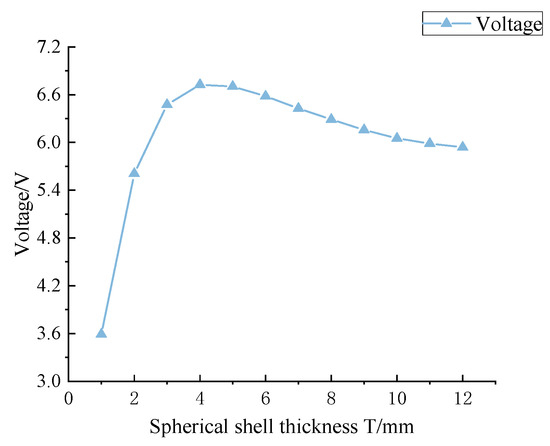
Figure 29.
Peak voltage under different spherical shell thicknesses.
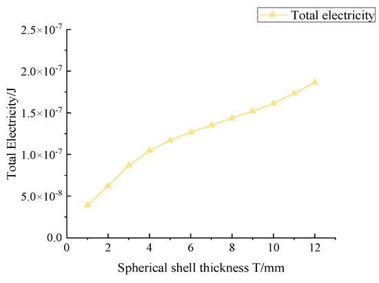
Figure 30.
Total electricity under different spherical shell thicknesses.
When the spherical shell thickness varied in the range of 1~12 mm, the peak stress and vertical displacement of the energy harvester were within the safety range, so the electrical properties were also given priority to determine the thickness of the spherical shell. When the thickness of the spherical shell was 4 mm, the peak voltage of the energy harvester can be taken to the maximum value of 6.7 V, which meets the minimum output voltage requirement (0.4~1.5 V). At this time, the total electricity was 1.05 × 10⁻⁷ J, and the optimal spherical shell thickness was 4 mm.
Through numerical simulation of the dimension parameters H, R, I, and T of the spherical energy capture structure, it was found that the peak voltage and total electricity of the spherical energy structure increased with the increase in piezoelectric layer thickness H. The peak voltage first increased and then decreased when increasing the piezoelectric layer radius R, and the total electricity increased with the increase in piezoelectric layer radius R. The peak voltage and total electricity decreased with the increase in spherical shell axial ratio I. The peak voltage first increased and then decreased with the spherical shell thickness T getting larger, and the total electricity increased with the thickness T of the spherical shell. Considering obtaining better electrical performance and combining it with the actual situation, the optimal size of the spherical energy harvester was obtained as shown in Table 5, and the energy harvester cell under the optimal size is shown in Figure 31.
Table 5.
Optimal size parameters.
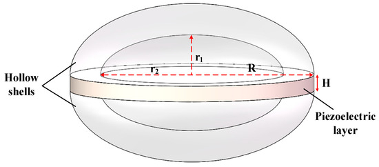
Figure 31.
Optimal size model of the spherical energy harvester.
6. Conclusions
For the rubber bearing floating slab track, a spherical energy harvester was designed, and the mechanical and electrical properties of the disk, cymbal, and spherical energy harvesters were compared by numerical simulation. Furthermore, the geometric parameters of the spherical energy harvester were optimized. The conclusions are as follows:
- (1)
- Compared with the disk and cymbal energy harvester, the spherical energy harvester had better electrical and mechanical properties and showed less stress concentration. The output voltage of the spherical energy harvester was 11 times that of the disk one, and the total electricity output was 20% more than that of the cymbal energy harvester.
- (2)
- By calculating the output power of the energy harvesters under load match, we found that the output power of the spherical energy harvester was two orders of magnitude higher than that of the disk one and 53% higher than that of the cymbal one, being able to reach the microwatt level under impedance match.
- (3)
- The optimal dimensions of the spherical energy harvester were piezoelectric layer thickness h = 2 mm, piezoelectric layer radius r = 16 mm, spherical shell axis ratio I = 0.4, and spherical shell thickness t = 4 mm.
- (4)
- The spherical energy harvesters had better mechanical and electrical properties than the traditional energy harvesting structure, so it has broad prospects in the field of energy harvesting of rail transit and other energy harvesting fields.
- (5)
- This paper creatively proposed a new spherical energy harvesting structure and applied it to energy harvesting in the field of rail transit. In the future, it can also be applied to the field of energy harvesting under long-term heavy load such as road surface.
The summary of abbreviations and symbols is shown in Appendix A.
Author Contributions
Conceptualization, S.Y.; methodology, H.J.; software, Z.L.; validation, J.Y.; formal analysis, D.Y.; investigation, S.Y.; resources, Z.L.; data curation, D.Y.; writing—original draft preparation, Z.L.; writing—review and editing, S.Y.; visualization, H.J.; supervision, J.Y.; project administration, H.J.; funding acquisition, H.J. All authors have read and agreed to the published version of the manuscript.
Funding
This research was funded by [the Natural Science Foundation of Jiangsu Province] grant number [BK20211173], [China Postdoctoral Science Foundation] grant number [2022M722958], and [Key R&D Program of Zhejiang] grant number [2023C03182].
Institutional Review Board Statement
Not applicable.
Informed Consent Statement
Not applicable.
Data Availability Statement
The data presented in this study are available on request from the corresponding author. The data are not publicly available due to copyright restrictions.
Conflicts of Interest
Author Shuo Yu and Jiajia Yan were employed by the company PowerChina HuaDong Engineering Corporation Limited. The remaining authors declare that the research was conducted in the absence of any commercial or financial relationships that could be construed as a potential conflict of interest.
Appendix A
| the thickness of force transmission structures | |
| D | the thickness of the disk piezoelectric layer |
| the diameter of the disk energy harvester | |
| the thickness of the metal cap | |
| the thickness of the cymbal piezoelectric layer | |
| the inner cavity bottom diameter | |
| the inner cavity top diameter | |
| the height of the inner cavity | |
| the diameter of cymbal energy harvester | |
| piezoelectric strain constant | |
| the piezoelectric stress constant | |
| and | relative dielectric constants |
| relative dielectric constant | |
| , , , , , , | the elastic coefficients |
| density | |
| H | piezoelectric layer thickness |
| R | piezoelectric layer radius |
| r1 | vertical axis radius of the inner cavity of the spherical shell |
| r2 | horizontal axis radius of the inner cavity of the spherical shell |
| I | axis ratio |
| T | spherical shell thickness |
| R0 | equivalent internal resistor of the energy harvester |
| C0 | equivalent capacitance |
| RL | load resistor |
| vacuum dielectric constant | |
| piezoelectric layer area | |
| capacitive impedance | |
| external load resistance | |
| matching impedance | |
| V | voltage source |
References
- Xu, L.; Ma, M. Dynamic response of the multilayered half-space medium due to the spatially periodic harmonic moving load. Soil Dyn. Earthq. Eng. 2022, 157, 107246. [Google Scholar] [CrossRef]
- Jin, H.; Tang, S.; Zhao, C.; Jiang, B. Study on vibration propagation characteristics caused by segments joints in shield tunnel. Int. J. Struct. Stab. Dyn. 2023, 23, 2350156. [Google Scholar] [CrossRef]
- Li, J.; Jang, S.; Tang, J. Implementation of a piezoelectric energy harvester in railway health monitoring. Proc. SPIE 2014, 9061, 90612Q. [Google Scholar] [CrossRef]
- Zhang, X.; Zhang, Z.; Pan, H.; Salman, W.; Yuan, Y.; Liu, Y. A portable high-efficiency electromagnetic energy harvesting system using supercapacitors for renewable energy applications in railroads. Energy Convers. Manag. 2016, 118, 287–294. [Google Scholar] [CrossRef]
- Yuan, T.; Yang, J.; Song, R.; Liu, X. Vibration energy harvesting system for railroad safety based on running vehicles. Smart Mater. Struct. 2014, 23, 125046. [Google Scholar] [CrossRef]
- Wang, J.; Penamalli, G.; Zuo, L. Electromagnetic energy harvesting from train induced railway track vibrations. In Proceedings of the 2012 IEEE/ASME 8th IEEE/ASME International Conference on Mechatronic and Embedded Systems and Applications, Suzhou, China, 8–10 July 2012; pp. 29–34. [Google Scholar] [CrossRef]
- Lin, T.; Pan, Y.; Chen, S.; Zuo, L. Modeling and field testing of an electromagnetic energy harvester for rail tracks with anchorless mounting. Appl. Energ. 2018, 213, 219–226. [Google Scholar] [CrossRef]
- Hou, W.; Zheng, Y.; Guo, W.; Guo, P. Piezoelectric vibration energy harvesting for rail transit bridge with steel-spring floating slab track system. J. Clean. Prod. 2021, 291, 125283. [Google Scholar] [CrossRef]
- Mohamed, M.; Wu, W.; Moniri, M. Power harvesting for smart sensor networks in monitoring water distribution system. In Proceedings of the 2011 International Conference on Networking, Sensing and Control, Delft, The Netherlands, 11–13 April 2011; pp. 393–398. [Google Scholar] [CrossRef]
- Lee, B.; Lin, S.; Wu, W.; Wang, X.; Chang, P.; Lee, C. Piezoelectric mems generators fabricated with an aerosol deposition pzt thin film. J. Micromech. Microeng. 2009, 19, 065014. [Google Scholar] [CrossRef]
- Fang, H.; Liu, J.; Xu, Z.; Dong, L.; Wang, L.; Chen, D.; Cai, B.; Liu, Y. Fabrication and performance of mems-based piezoelectric power generator for vibration energy harvesting. Microelectron. J. 2006, 37, 1280–1284. [Google Scholar] [CrossRef]
- Shen, D.; Park, J.; Ajitsaria, J.; Choe, S.; Wikle, H.; Kim, D. The design, fabrication and evaluation of a mems pzt cantilever with an integrated si proof mass for vibration energy harvesting. J. Micromech. Microeng. 2008, 18, 055017. [Google Scholar] [CrossRef]
- Dagdeviren, C.; Hwang, S.; Su, Y.; Kim, S.; Cheng, H.; Gur, O.; Haney, R.; Omenetto, F.; Huang, Y.; Rogers, J. Transient, biocompatible electronics and energy harvesters based on zno. Small 2013, 9, 3398–3404. [Google Scholar] [CrossRef] [PubMed]
- Cho, K.; Park, H.; Heo, J.; Priya, S. Structure-performance relationships for cantilever-type piezoelectric energy harvesters. J. Appl. Phys. 2014, 115, 204108. [Google Scholar] [CrossRef]
- Cui, Y.; Zhang, Q.; Yao, M.; Dong, W.; Gao, S. Vibration piezoelectric energy harvester with multi-beam. AIP Adv. 2015, 5, 041332. [Google Scholar] [CrossRef]
- Sahi, Y.; Chandan, S. Finite element analysis of lead-free ceramic based cymbal transducer for energy harvesting. Integr. Ferroelectr. 2020, 212, 81–88. [Google Scholar] [CrossRef]
- Chen, Y.; Gao, M.; Yu, W.; Zhang, L. On energy harvesting characteristics of cymbal transducer. Appl. Mech. Mater. 2013, 365–366, 1318–1323. [Google Scholar] [CrossRef]
- Palosaari, J.; Leinonen, M.; Hannu, J.; Juuti, J.; Jantunen, H. Energy harvesting with a cymbal type piezoelectric transducer from low frequency compression. J. Electroceramics 2012, 28, 214–219. [Google Scholar] [CrossRef]
- Kamata, Y.; Yoon, D.; Sasaki, T.; Nozaki, Y.; Yamaura, S.; Sekiguchi, T.; Nakajima, T.; Shoji, S. Stacked piezoelectric energy harvesting device by printing process. Micro Nano Lett. 2016, 11, 650–653. [Google Scholar] [CrossRef]
- Wang, C.; Wang, S.; Li, Q.; Wang, X.; Gao, Z.; Zhang, L. Fabrication and performance of a power generation device based on stacked piezoelectric energy-harvesting units for pavements. Energy Convers. Manag. 2018, 163, 196–207. [Google Scholar] [CrossRef]
- Zhao, H.; Qin, L.; Ling, J. Test and analysis of bridge transducers for harvesting energy from asphalt pavement. Int. J. Transp. Sci. Technol. 2015, 4, 17–28. [Google Scholar] [CrossRef]
- Yao, L.; Zhao, H.; Dong, Z.; Sun, Y.; Gao, Y. Laboratory testing of piezoelectric bridge transducers for asphalt pavement energy harvesting. Key Eng. Mater. 2011, 492, 172–175. [Google Scholar] [CrossRef]
- Wang, F.; Wu, W.; Lozowski, A.; Alizadehyazdi, V.; Amin, A. Energy harvesting with a piezoelectric thunder. In Proceedings of the ASME 2015 International Mechanical Engineering Congress and Exposition, Houston, TX, USA, 13–19 November 2015. [Google Scholar]
- Wang, F.; Wang, Z.; Soroush, M.; Abedini, A. Energy harvesting efficiency optimization via varying the radius of curvature of a piezoelectric thunder. Smart Mater. Struct. 2016, 25, 095044. [Google Scholar] [CrossRef]
- Wise, S. Displacement properties of rainbow and thunder piezoelectric actuators. Sens. Actuators A Phys. 1998, 69, 33–38. [Google Scholar] [CrossRef]
- Peddigari, M.; Kim, G.; Park, C.; Min, Y.; Kim, J.; Ahn, C.; Choi, J.; Hahn, B.; Choi, J.; Park, D.; et al. A comparison study of fatigue behavior of hard and soft piezoelectric single crystal macro-fiber composites for vibration energy harvesting. Sensors 2019, 19, 2196. [Google Scholar] [CrossRef] [PubMed]
- Lin, X.; Zhou, K.; Zhang, X.; Zhang, D. Development, modeling and application of piezoelectric fiber composites. Trans. Nonferrous Met. Soc. China 2013, 23, 98–107. [Google Scholar] [CrossRef]
- Mallouli, M.; Chouchane, M. Piezoelectric energy harvesting using macro fiber composite patches. Proc. Inst. Mech. Eng. Part C J. Mech. Eng. Sci. 2020, 234, 4331–4349. [Google Scholar] [CrossRef]
- Panigrahi, B.; Sitikantha, D.; Bhuyan, A.; Panda, H.; Mohanta, K. Dielectric and ferroelectric properties of pvdf thin film for biomechanical energy harvesting. Mater. Today Proc. 2021, 41, 335–339. [Google Scholar] [CrossRef]
- Kim, H.; Batra, A.; Priya, S.; Uchino, K.; Markley, D.; Newnham, R.; Hofmann, H. Energy harvesting using a piezoelectric “cymbal” transducer in dynamic environment. Jpn. J. Appl. Phys. 2004, 43, 6178–6183. [Google Scholar] [CrossRef]
- Zhao, H.; Yu, J.; Ling, J. Finite element analysis of cymbal piezoelectric transducers for harvesting energy from asphalt pavement. J. Ceram. Soc. Jpn. 2010, 118, 909–915. [Google Scholar] [CrossRef]
- Yesner, G.; Jasim, A.; Wang, H.; Basily, B.; Maher, A.; Safari, A. Energy harvesting and evaluation of a novel piezoelectric bridge transducer. Sens. Actuators A Phys. 2019, 285, 348–354. [Google Scholar] [CrossRef]
- Liu, X.; Wang, J. Performance exploration of a radially layered cymbal piezoelectric energy harvester under road traffic induced low frequency vibration. Iop Conf. Ser. Mater. Sci. Eng. 2019, 542, 12075. [Google Scholar] [CrossRef]
- Jin, H.; Li, Z.; Wang, Z.; Tang, S. Vibration energy harvesting from tunnel invert-filling using rubberized concrete. Environ. Sci. Pollut. Res. 2023, 30, 30167–30182. [Google Scholar] [CrossRef] [PubMed]
- Citroni, R.; Di Paolo, F.; Livreri, P. Evaluation of an optical energy harvester for SHM application. AEU Int. J. Electron. Commun. 2019, 111, 152918. [Google Scholar] [CrossRef]
- Sezer, N.; Koc, M. A comprehensive review on the state-of-the-art of piezoelectric energy harvesting. Nano Energy 2021, 80, 105567. [Google Scholar] [CrossRef]
Disclaimer/Publisher’s Note: The statements, opinions and data contained in all publications are solely those of the individual author(s) and contributor(s) and not of MDPI and/or the editor(s). MDPI and/or the editor(s) disclaim responsibility for any injury to people or property resulting from any ideas, methods, instructions or products referred to in the content. |
© 2023 by the authors. Licensee MDPI, Basel, Switzerland. This article is an open access article distributed under the terms and conditions of the Creative Commons Attribution (CC BY) license (https://creativecommons.org/licenses/by/4.0/).