Abstract
Piezoelectric actuators and sensors can be incorporated into aerospace structures to suppress unwanted flexible oscillations. These devices need to interact with various passive structures, including innovative materials such as thermoplastic composites, which offer several advantages over traditional options. This study explores the application of a piezoelectric-based vibration control system on a lightweight carbon-reinforced thermoplastic material. Numerical and experimental investigations are conducted to assess the mechanical properties and damping behavior of the composite. As a case study, an equivalent orthotropic shell laminate is developed to facilitate finite element modeling of two composite solar panel structures equipped to a spacecraft. Moreover, an electro-mechanical formulation is implemented to integrate smart actuators and sensors onto the composite hosting structure. Finally, the efficiency of the active vibration control system is assessed when significant vibration perturbations are caused on the panels by rigid–flexible dynamics coupling during agile attitude maneuvers. The results demonstrate the damping factor of the material can be noticeably improved, making the proposed system a promising technological solution for further aerospace applications.
1. Introduction
In aerospace systems, the interaction between rigid and flexible dynamics generally leads to relevant elastic disturbances, often compromising the desired performance and target requirements [1,2,3]. Rigid–flexible coupled models are required to properly represent and study such complex and multidisciplinary phenomena, as in the case of aircraft wings, helicopter blades, and flexible satellites. At the same time, innovative materials are currently studied to reduce mass and enhance mechanical and thermal properties [4], often leading to lightweight components and structures, but also to increased overall flexibility. Among these materials, thermoplastic composites have demonstrated their appeal as a technological solution for aerospace applications in a wide range of temperatures, offering several advantages over more traditional materials such as thermosetting composites and metal alloys [5]. Several applications have already implemented carbon-reinforced thermoplastics, and a relevant body of research is currently proposing additional uses. Jha et al. [6] designed and analyzed a trainer aircraft’s wing by replacing the aluminum and epoxy-carbon fiber composites with carbon fiber-reinforced poly-ether-ether-ketone (CF-PEEK) composites, showing that the latter had lower deformations and higher frequencies, while exhibiting stress levels comparable with traditional materials. Yao et al. [7] proposed an innovative thermoplastic composite fastener based on CF-PEEK, with a higher specific joint strength than titanium, scalable by varying the carbon fiber mass fraction. Flanagan et al. [8] presented an experimental investigation into the permeability of CF-PEEK for cryogenic storage tanks for aerospace applications, and demonstrated that—in the absence of damages—the permeability remains essentially constant for different ranges of thickness and temperature. Chadwick et al. [9] proposed and realized a primary CF-PEEK structure for a sounding rocket mission. Lanouette et al. [10] investigated the effect of debris impact damage on a space robotic arm–cylinder shell realized in carbon-reinforced PEEK. Concerning the automotive sector, composite innovative materials are proposed for future mobility as in the work from Lee et al. [11], for carbon-based accumulators from Malozyomov et al. [12], and for lightweight wheels from Gardie et al. [13].
Overall, the diffusion of lightweight and flexible composite materials has paved the way to explore and address challenges related to damping performance in several applications. Aside from researching technological manufacturing solutions to improve damping factors for composite materials [14], new approaches are needed to ensure satisfactory dynamic behavior beyond traditional strategies [15]. Active Vibration Control (AVC) emerges as one of the most promising solutions in this regard. Several approaches can be applied to this problem, ranging from the type of actuators/sensors to be implemented on passive structures, to the control algorithm. Specifically, smart materials such as piezoelectric actuators/sensors are considered some of the most mature devices that can be installed on aerospace structures to suppress unwanted flexible oscillations [16,17,18]. This is particularly relevant in the space sector, including those applications demanding satellites to be compliant to high precision pointing accuracy and structural stability [19]. Indeed, flexible appendages equipped to spacecraft are highly impacted by the rigid/flexible dynamics interaction phenomenon, particularly while performing agile maneuvers (i.e., fast re-orientations) [20]. To choose a relevant case study in this regard, and to keep generality of application, a solar panel structure is selected in this paper to evaluate the vibration suppression performance of a piezo-based AVC system on a CF-PEEK material. Indeed, the dynamic behavior of flexible plates is critical to the effective operation of many structures and can be transferred to other sectors such as automotive and aircrafts platforms.
This paper aims to explore the application of a piezoelectric-based vibration control system on an innovative lightweight thermoplastic composite. In Section 2, extensive numerical and experimental investigations are presented to assess the thermoplastic material’s properties. Based on the acquired knowledge, an equivalent orthotropic shell laminate is developed to enable the modeling of a solar panel in a finite element analysis environment. Then, an equivalent electro-mechanical coupled finite element formulation to describe a plate with integrated smart actuators and sensors elements is presented in Section 3. The resulting structural model includes electrical inputs/outputs and incorporates modified structural properties resulting from the additional piezo devices. Section 4 illustrates the results of the AVC performance assessment by varying the numerically computed damping factor of the thermoplastic material. Finally, more remarks and discussions are reported in Section 5 and Section 6.
2. Materials and Methods
Composite materials are drawing significant attention from both academic and industrial environments due to their diverse range of applications. Generally, such materials consist of a matrix and a reinforcement phase. The latter is commonly composed of glass or carbon fibers, whereas the matrix can be of various types, including polymeric, ceramic, or metallic. In the aerospace industry, composite materials play a crucial role to obtain the most convenient trade-off among lightness, performance, and reliability, so that polymeric-matrix carbon-based material is one of the most promising solutions [21,22,23].
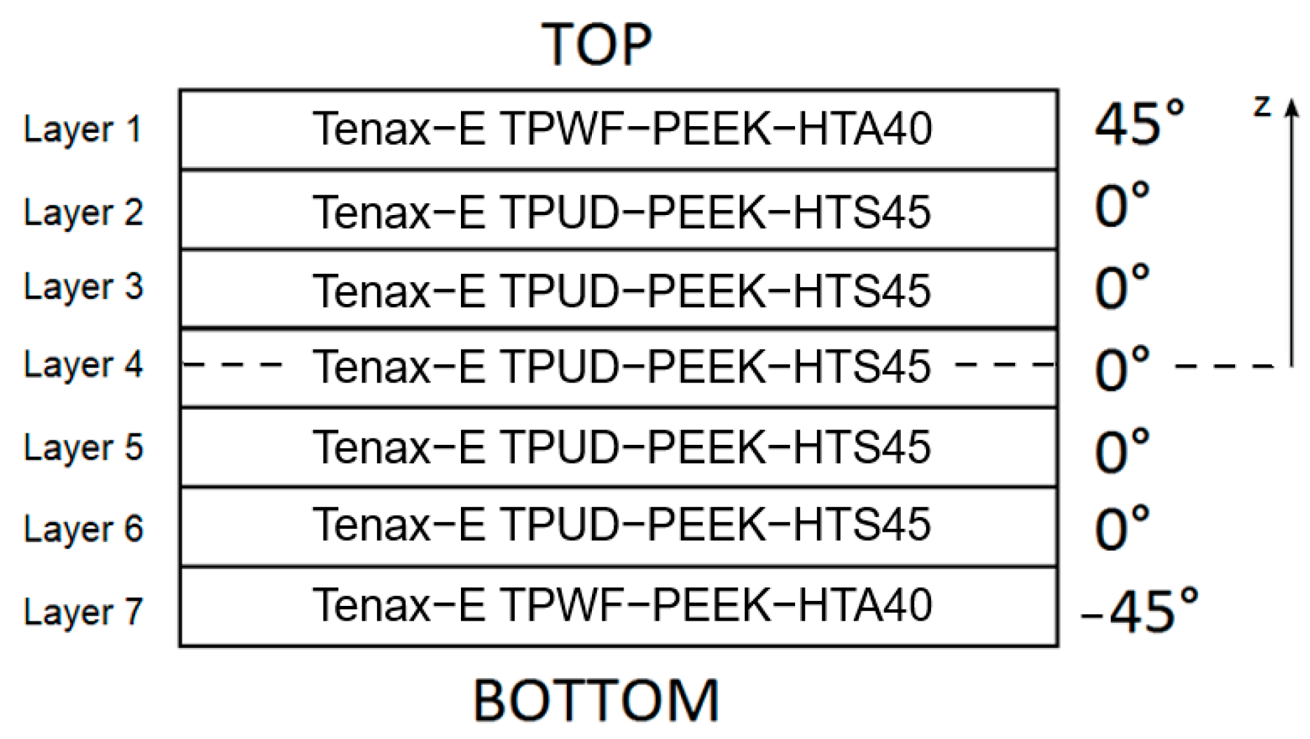
The material of the panels analyzed in this paper (which will be presented in Section 3) is here introduced and characterized. The objective is to obtain properties to be used to reproduce a 2D equivalent orthotropic finite element model of the composite complete laminate. In detail, a carbon/PEEK composite material made of seven laminates is considered: the two external layers (top and bottom) are realized in bidirectional pre-preg Tenax-E_TPWF-PEEK-HTA40, while the five internal ones are unidirectional (UD) laminates of Tenax-E_TPUD-PEEK-HTS45. Both materials were purchased from Teijin Carbon Europe GmbH (Germany). The stacking sequence is 45°/0°/0°/0°/0°/0°/−45°, with the 0° as shown in Figure 1. The overall thickness of the laminate package is determined by adding up the thicknesses of each individual layer, resulting in an approximate measurement of 1.3 mm.
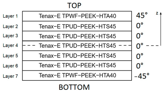
Figure 1.
Laminate stacking sequence of carbon/PEEK composite material.
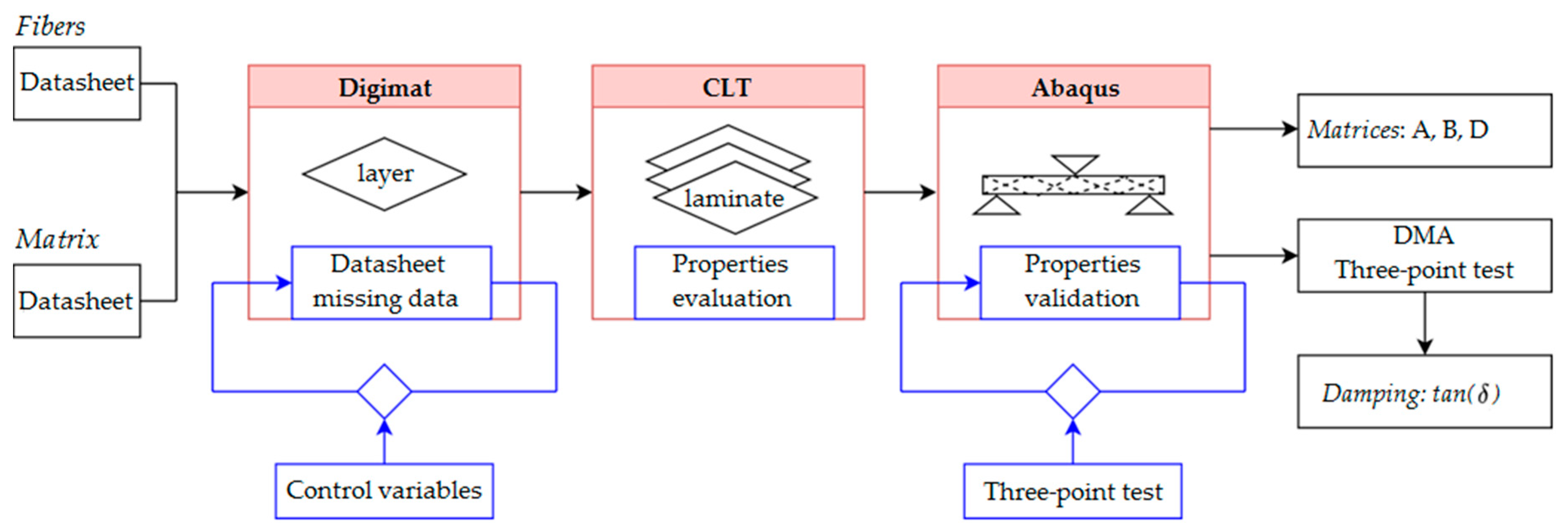
Figure 2 depicts the flowchart illustrating the various phases of characterization, which are elaborated on in the subsequent sections. The complete set of material properties is generally not fully provided in datasheets. Therefore, to obtain the desired quantities, a series of numerical simulations and experimental tests was carried out at the SASLab, DIAEE Sapienza University of Rome. In the first phase, the individual layers were modeled in Digimat finite element environment, starting from the known properties of the constituent phases (fibers and matrix). Unknown parameters were found by matching simulation results with available information from datasheets, thus achieving a full characterization of each lamina. Then, the numerically computed data were validated by conducting quasi-static three-point bending tests on the laminate, and by modeling the flexural tests in the finite element software Abaqus, adopting the properties of the individual laminate previously determined via Digimat. Classic Laminate Theory (CLT) was followed to compose the set of the constitutive matrices (namely, the extensional stiffness matrix A, the coupling stiffness matrix B and bending stiffness matrix D) for the composite material, to be used as input in subsequent analyses. Finally, the longitudinal storage modulus and the structural damping factor were evaluated experimentally as functions of temperature via dynamical mechanical analysis (DMA).
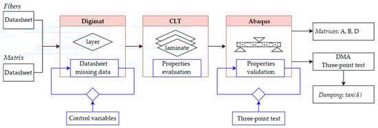
Figure 2.
Flowchart of the material characterization activities: the two types of layers (i.e., Tenax-E_TPWF-PEEK-HTA40 and Tenax-E_TPUD-PEEK-HTS45) were numerically characterized starting from the datasheet properties, then the laminate package equivalent orthotropic properties were obtained using CLT. Experimental tests were conducted and simulated to validate the characterization. Dedicated tests were carried out to find the damping factor.
2.1. Multiscale Analysis via Digimat
Digimat is a well-established analysis tool to perform multi-scale simulations of composite materials. In this paper, the representative volume element (RVE) formulation was used to obtain the laminate properties: a unitary cell connected the microscopic scale, where the properties of the single phases were the inputs, and the macroscopic scale, where the composite properties were the outputs. The known properties of the materials, used to perform the numerical characterization of the two lamina types, can be found in datasheets [24,25]. In detail, the phases parameters were given as input to Digimat FE 2021.2. Table 1 collects input parameters evaluated to achieve correspondence in the analysis in terms of known outputs (lamina tensile modulus and nominal thickness).

Table 1.
Calibrated properties of materials using multiscale analysis.
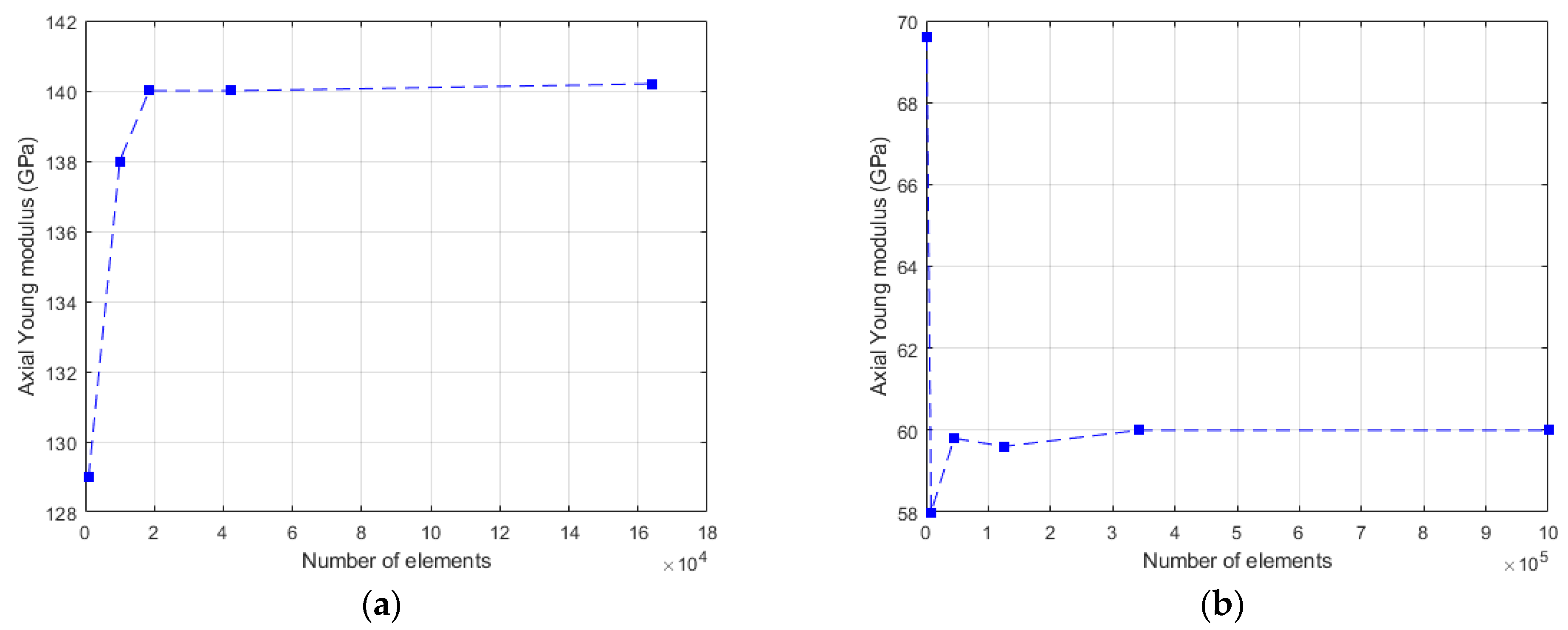
After deriving such properties, RVEs were created: the unidirectional (UD) RVE was meshed with a conforming mesh of 42,000 elements, while the bidirectional fabric’s RVE was meshed with a voxel mesh of 343,000 elements (Figure 3). The element types were tetrahedral and brick, respectively. Specifically, the number of finite elements was finalized after a convergence analysis conducted on the Young’s Modulus value (Figure 4). Figure 4 shows that a coarse mesh can yield inconsistent outcomes attributed to excessive geometric simplification (coarse mesh). More reliable results were achieved by increasing the number of elements, thereby approaching stable values. The properties of the composites reported in Table 2 are outcomes from the multiscale analyses.
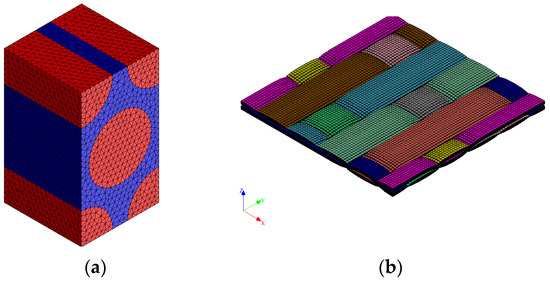
Figure 3.
Meshed RVE of: (a) UD carbon fiber/PEEK, (b) bidirectional carbon fiber/PEEK.
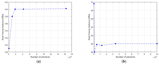
Figure 4.
Mesh convergence analysis for: (a) UD carbon fiber/PEEK, (b) bidirectional carbon fiber/PEEK.
Table 2.
Mechanical properties evaluated via Digimat.
2.2. Experimental Validation: Three-Point Bending Test Campaign
To verify the correct modeling of the material, quasi static three-point bending tests were simulated and performed on composite samples according to ASTM D790 (as illustrated in Figure 5). The test sample was discretized with 103 four-node (S4R) shell elements, which led to assess a stable numerical result of 32.98 GPa for the bending stiffness. A good agreement was obtained after carrying out bending experiments on a 10 kN Autograph AGS-X Shimadzu testing machine, as the evaluated modulus was 32.47 ± 0.95 GPa. The elastic modulus was calculated from load-deflection data measured during the tests. According to the standard, five rectangular specimens, each measuring 95 mm in length and 20 mm in width, were tested. The specimens were tested with a span-to-thickness ratio of 40 and a crosshead motion rate of 1 mm/min.
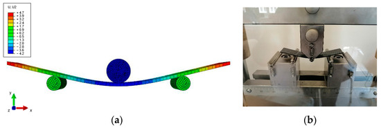
Figure 5.
Three-point bending tests: (a) numerical simulation; (b) experimental test. Note: vertical displacements are indicated in the figure as U2 and expressed in mm.
2.3. Laminate Properties
The individual layer properties were used to compute the A, B, and D matrices for the equivalent orthotropic shell laminate according to CLT [26] and can be expressed as:
where is the stiffness matrix rotated from C (which is the stiffness matrix of a base layer whose fibers are parallel to the global coordinate direction, i.e., a 0-degree angle). The subscript k denotes the layer, the total number of layers, and z the laminate package thickness coordinate originating from its centroid (Figure 1).
The mean density of the laminate is . The obtained values were as follows
To completely characterize the laminate, three-point bending tests were completed via a dynamical mechanical analysis (DMA). In this test, the storage modulus and loss modulus are measured. The damping factor is computed as the ratio between the two moduli. Tests were carried out in a temperature range from 30 °C to 200 °C using four samples to verify temperature influence on the laminate properties. Figure 6 shows a scheme of this kind of test (a), and the actual experimental setup (b). Sample dimensions were 40 mm × 15 mm × 1.32 mm.
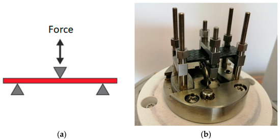
Figure 6.
DMA three-point bending test: (a) schematic representation; (b) sample mounted for experimental tests.
To perform the DMA tests, other parameters had to be selected, including the distance between the inferior supports (i.e., the span), the frequency at which the soliciting force was applied, the offset force, and the displacement amplitude. The span value was settled to 35 mm according to the DMA’s software preliminary evaluation about the expected modulus magnitude. Concerning the frequency, a standard value of 1 Hz was used. The offset force and the displacement amplitude were found to be equal to 3 N and 10 µm after preliminary dedicated tests.
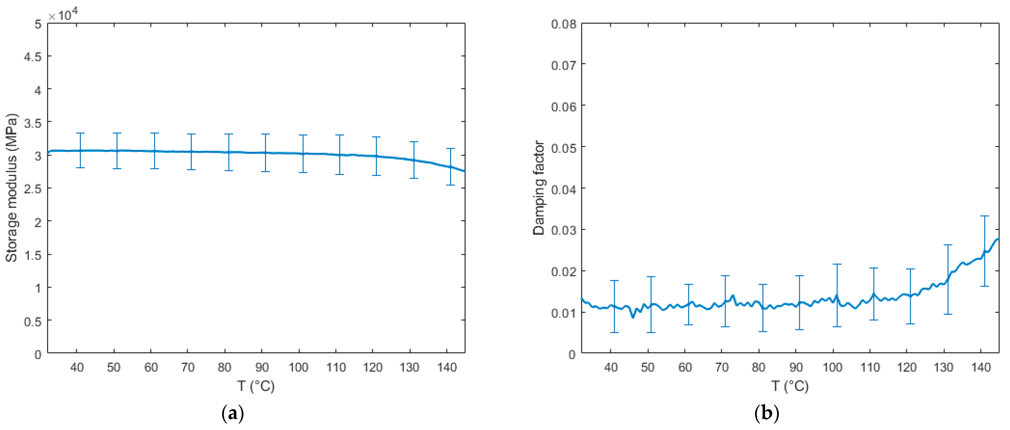
Figure 7 depicts the tests results for the storage modulus and the damping factor. The modulus at the test starting temperature (30 °C) was 30.25 ± 3.25 GPa, in agreement with the value obtained after the quasi static three-point bending tests described in Section 4.2. Increasing the temperature, the glass transition temperature of the matrix (143 °C) was reached and the material softened. However, the modulus decrease was limited, with around 27 GPa at 150 °C and 21 GPa at 200 °C. Concerning the damping factor, we identified three regions approximated by a linear behavior for : in the range T < 118 °C, mean value was equal to 0.012; and increased until reaching at 160 °C. From 160 to 200 °C, decreased to a value of 0.025.
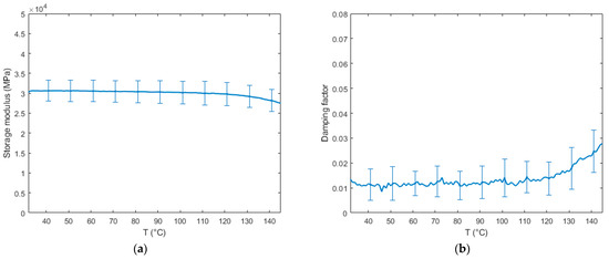
Figure 7.
Properties as a function of temperature: (a) Storage modulus; (b) Damping factor.
In the analyzed case study, i.e., a solar panel, environmental temperatures are considered to vary up to 130 °C, as for analogous composite structures in space operating conditions [27,28]. Hence, the modulus of the material could be assumed constant in the examined temperature range, while the damping factor was characterized by a higher relative variation, and its change was taken into account in the numerical simulations.
The experimentally validated properties of the seven-layer laminate are used in the next section as input for the material composing the satellite solar panels.
2.4. Equivalent Composite Material: From Multi-Layer to One-Layer Plates
Typically, a multi-layer model is created in a finite element analysis setting to replicate the composite structural behavior. Consequently, each layer is individually modeled, potentially requiring a large number of elements, as it can be deduced from Figure 3. This procedure is particularly challenging when aiming at building the complex model of a satellite equipped with flexible appendages, where only a few modes and nodes of interest can be retained in the system equations to proceed with the rigid/flexible control design. Therefore, it is feasible to develop an equivalent stiffness model of the composite plate using a reduced number of elements. The derivation of the material properties for an equivalent one-layer two-dimensional orthotropic finite element model is discussed in this section. After obtaining the constitutive matrices of the laminate at a macroscale level, the matrix in Equation (7) can be rewritten for a 2D orthotropic plate according to classical CLT for a one-layer orthotropic material [29] as
with
where and longitudinal and transversal elasticity moduli, in-plane shear modulus, and in-plane Poisson’s ratio. By equating the values of Equations (6) and (7), i.e., , it is possible to derive the values of the properties , , which are used to create the equivalent material for the satellite one-layer plates. It is worth noticing that such terms are derived based on the values computed via the micro- and macro-models of the fibers and matrices presented in Section 2.2 and Section 2.3.
According to Nashif and Chen [30,31,32], it is possible to relate the damping factor η with the damping ratio ( being the critical viscous damping coefficient, where k and m are the stiffness and mass of the system, respectively) providing that there is a low level of damping in the structure and that the displacements can be considered linear. If these hypotheses are true, then we have
On account of this relationship, it is clear that, by using DMA experimental test, it is possible to determine the classical damping ratio by a direct measurement of .
3. Spacecraft Dynamics
A model of the dynamic behavior of a satellite equipped with two solar panels is developed here as a study case to test the active vibration control strategy on the innovative lightweight composite structure.
3.1. Spacecraft Model
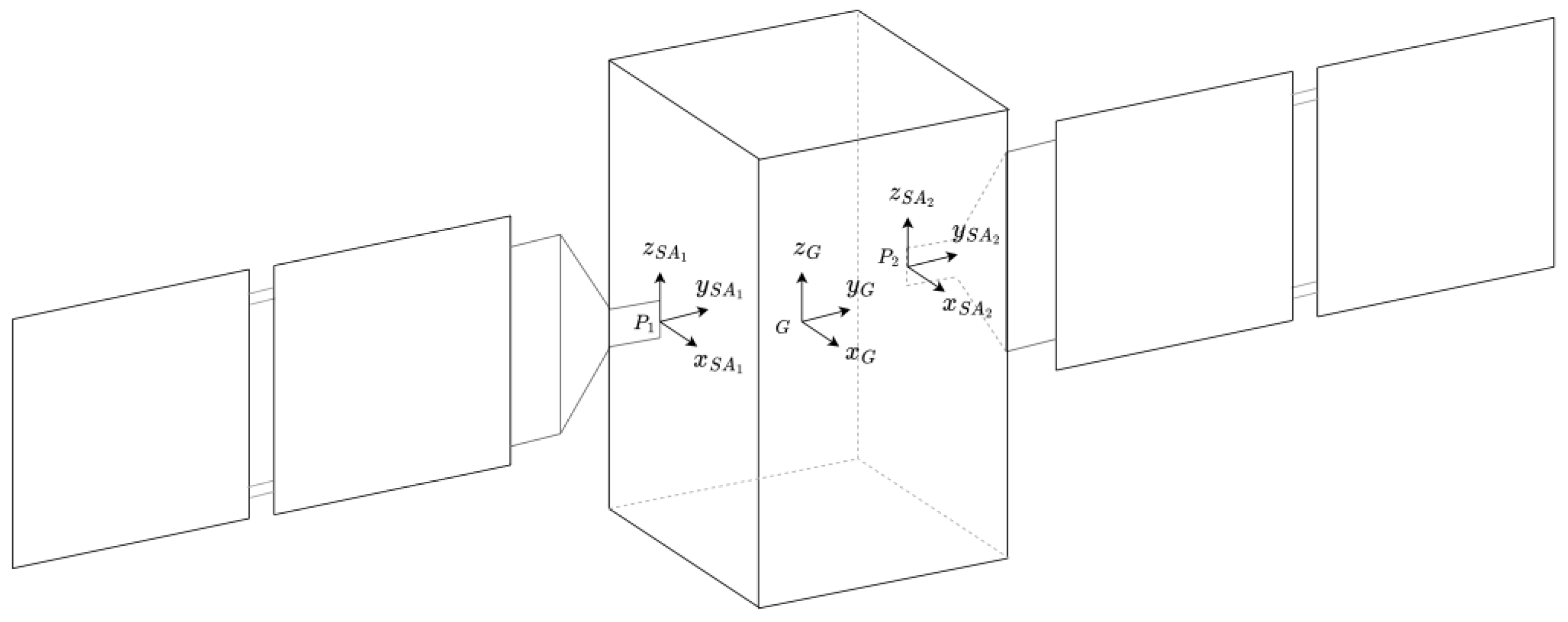
The satellite model considered here represents a realistic Earth Observation (EO) spacecraft and consists of a parallelepiped central platform along with two solar arrays, each measuring 1 × 3 m (in turn composed of two 1 × 1 m sub-panels). The panels are connected to the central hub, which is considered rigid with respect to the flexible appendages. The spacecraft’s reference frame has its origin G located at the vehicle’s CoG (refer to Figure 8), while two body reference frames for the panels originate in the attachment points and . The solar panels are realized as a one-layer equivalent composite material whose material properties were derived in Section 2.4. Moreover, a yoke structure replicates the panel’s attachment to the platform. Since the central hub is assumed to be rigid, the flexible substructures are directly assembled in MSC Nastran. Rigid body element connections are utilized to link them to a single node coinciding with point G. The relevant data, including inertial properties, modal participation factors, and natural frequencies of the flexible structure, computed with respect to point G, are imported into a Matlab environment to implement the dynamics of the flexible spacecraft, as described in Section 3.1. The inertial properties of the system are presented in Table 3.
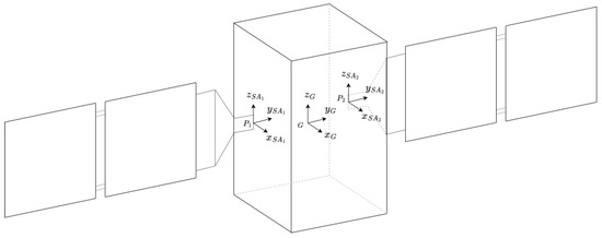
Figure 8.
Spacecraft model.
Table 3.
Spacecraft inertial properties.
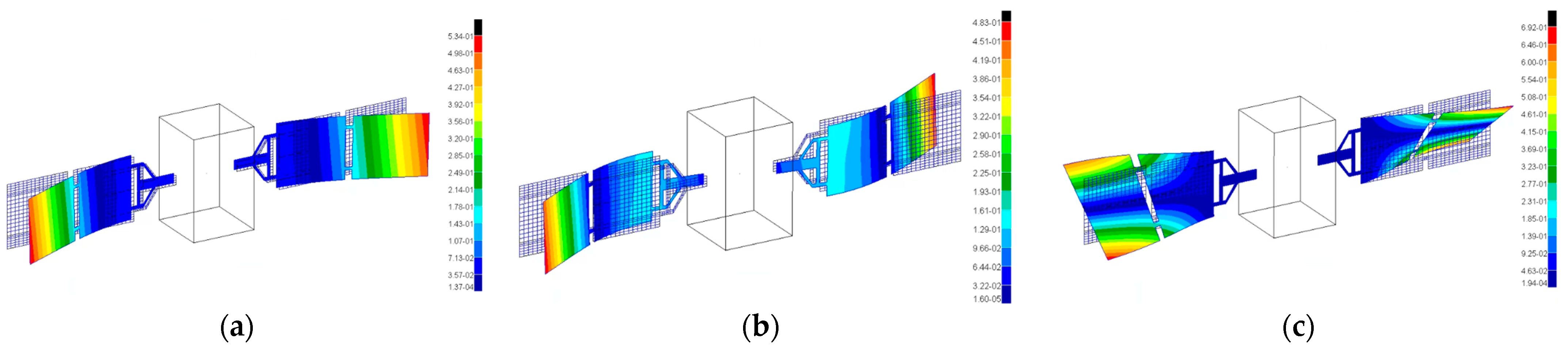
Panel-shaped structures exhibit three distinct constrained modes, which involve bending and torsion along the main coordinated axes. However, when these structures are installed on a satellite that also hosts other flexible appendages, their elastic modes interact with the overall system dynamics. Figure 9 provides a depiction of the assembled spacecraft’s modes, along with an overview of the complete system. The modal behavior of the system is characterized by both symmetric and asymmetric bending modes. Translation maneuvers trigger the symmetric bending modes, while attitude maneuvers excite the asymmetric bending modes.

Figure 9.
Spacecraft free-free modes: (a) 1st mode at 0.36 Hz, symmetric bending; (b) 2nd mode at 0.52 Hz, asymmetric bending; (c) 3rd mode at 1.29 Hz, torsion. Spectrum values illustrate the magnitude of normal modes eigenvectors, which are generally defined up to an arbitrary scale factor.
3.2. Governing Equations of Smart Structures
This section is dedicated to the introduction of the governing equation of a smart active structure and to the modeling approach used to cope with the uncertainties that appear in the knowledge of some parameters of the dynamic model. Generally, the system state vector can be defined as follows
where represents the position of the platform’s center of gravity (G) relative to an inertial frame (Figure 8), the attitude of the body reference frame in relation to the inertial system, and denotes the modal amplitudes of a flexible appendage attached to a central satellite platform. Therefore, the dynamic system of the general electro-elastic piezo-structure, which considers the mechanical properties of both passive and active elements, is described by the following set of equations:
where is the total mass matrix of the system, and are the damping and stiffness matrices, contains the non-linear dynamics terms and the generalized forces exerted on the system CoG (forces , torques , and projection of forces on the modal base), and are the input matrices of the piezo actuators and sensors, respectively, while and are the vectors including the voltages associated to the smart devices. The extended expression of the terms can be found in [33] and will not be presented here for the sake of brevity. In particular, the total mass matrix can be written as
where total mass of the active flexible spacecraft, with mass matrices of the i-th appendages, mass of the satellite platform, and mass matrices of the piezo actuators and sensors, respectively, with and influence vectors of the smart devices on the structure degrees of freedom [34], mass and number of the actuators and sensors respectively, total number of flexible appendages. The matrix also includes the following terms: skew matrix containing the static moment of the system, with respect to the spacecraft center of gravity G in the body reference frame, and total moment of inertia of the system with respect to G in the body frame. The variables and include the translation and rotation modal participation factors (coupling with the rigid motion), respectively, while is the identity matrix (structural modes are normalized with respect to mass). Moreover, the matrices and are defined as
where diagonal matrix containing all squared frequencies of the appendages cantilevered to the satellite, and diagonal matrix including the k—the damping factor of the corresponding elastic modes. In addition, is the matrix containing the structure modes, the stiffness matrix of the passive structure, and the stiffness matrices of the actuators and sensors, respectively, while and are the stiffness parameters of the smart devices. The finite element model includes a total of three flexible modes for each appendage. Moreover, the input matrices and can be written as
where and are the global electro-mechanical coupling matrices of the actuators and sensors, respectively, and is the number of rigid degrees of freedom of the spacecraft.
To fully describe the active system, Equation (11) should be coupled to the following relations concerning the piezoelectric actuators (indicated with the apex/subscript a) and sensors (written with apex/subscript s) [34]
with index of the i-th actuator, and index of the j-th sensor. The matrices , and , and the terms and will be introduced in the specific sections concerning smart devices, namely Section 3.2.1 and Section 3.2.2.
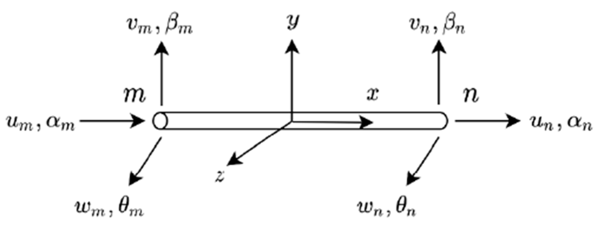
Let us now consider placing actuators and sensors on a flexible structure. In the considered application, the number of installed actuators and sensors is the same, and it yields . The devices are assumed to be implemented between two adjacent nodes m, n of the structure, each node with six degrees of freedom as follows:
where u, v, and z indicate the displacements along the local finite element x, y, and z-axis, respectively while α, β, and θ the rotations about the same axes (Figure 10).

Figure 10.
Two-nodes FEM element.
3.2.1. OPSA Actuators
This section is devoted to introducing the piezoelectric actuator used in this case study. It was indeed demonstrated [35,36] that we can obtain a bending control action more effective than piezoelectric patches if a piezoelectric stack actuator (i.e., multilayered piezo operating in mode) is mounted on two L-shaped mechanical frames at a certain distance from the surface of the passive structure. Specifically, the term “OPSA” stands for Offset Piezoelectric Stack Actuators, where the offset variable represents the separation between the neutral axis of the beam and the neutral axis of the stack
[36].
The bending moment generated by the actuator about the local z-axis in Figure 10 on the controlled flexible structure can be represented [34] as
where is the piezoelectric coefficient, is the actuation voltage, and , , , and are the area, Young modulus, length, and number of layers of the stack device, respectively. The complete derivation of Equation (18) can already be found in the work from Callipari et al. [36] and Preumont [34]. By referring to Equation (17), the influence vector of one actuator in the local finite element reference frame—i.e., the forces and moments that the actuator exerts on the passive structure degrees of freedom can be written as follows:
where the apex e indicates that the vector is referred to one finite element. Consequently, the electro-mechanical coupling matrix in the global 3D body reference frame can be assembled by multiplying rotation matrix (from the local to the global reference systems) by the local coupling matrix as
where , with number of the finite element model degrees of freedom and number of actuators. In detail, each column of the matrix describes the effect of one smart device on the structure and can be regarded as the influence vector presented in Equation (11).
The capacitance matrix of the element [34] is given as follows
The global capacitance matrix can be assembled under the same logic of the electromechanical coupling term. The properties of the selected actuator stack are listed in Table 4.
Table 4.
Piezo-stack actuator properties (from PI manufacturer catalogues).
3.2.2. Piezo Patch Sensors
The sensor device can be simulated using finite elements, similar to the approach used for modeling the passive structure. Specifically, a piezo patch, composed of a single layer of piezoelectric material sandwiched between two electrodes, can generate an electric charge when it experiences structural deformation. This electric charge, denoted as , is collected on the electrodes of the sensor and then processed through a current amplifier. Under the assumption of a Euler–Bernoulli beam and a sensor with a constant width, as demonstrated in [34], the charge can be derived as follows
where is the patch distance from the passive structure neutral plane, is the piezo electromechanical coefficient, is the sensor width, and is the integral of the structural curvature. It is clear that the sensor output is proportional to the difference of slopes (i.e., rotations) at the extremities of the sensor strip, which are here reconstructed via the finite elements structural model. Hence, the local element coupling term reads as
while the capacitance matrix of the element [34] is given as follows
with thickness of the sensor. The properties of the implemented sensor patch are reported in Table 5. The implementation from local element to global reference system can be carried out as described in Section 3.2.1.
Table 5.
Piezo patch sensor properties (from PI manufacturer catalogues).
3.3. Control Strategy
In this section, the active control strategy for the flexible panels is introduced. Then, this control law will work in parallel to an attitude re-orientation control in Section 4.
3.3.1. Vibration Control: Direct Velocity Feedback (DVF)
Substantial research work has been performed over the past decades on structural vibration reduction methods. One of the most effective yet straightforward approaches is the direct feedback control of the displacement and/or velocity measurements. When the system is stabilizable and detectable, the stability is guaranteed if the pairs of sensors and actuators are collocated and their gain matrices are positive definite [37]. As a subclass, the well-studied Direct Velocity Feedback (DVF) control implies that the output signals from velocity sensors are multiplied by gains and directly fed back to actuators. This controller was applied to space structure by Balas [38] and Ikeda et al. [39], guaranteeing that all vibration modes remained stable when the active control is in operation under perturbation of system dynamic parameters, minimizing spillover issues if a low number of modes was considered.
When the electrodes of a piezoelectric sensor are connected to an operational amplifier, they can be regarded as short-circuited and the electric field through the piezo can be set to zero [34]. The input current is converted into voltage as follows:
where R is the constant gain of the charge amplifier. The sensor output voltage can be fed back through an amplifier to the actuator. Hence, the definition of the actuator voltage is described hereafter
where gain of the feedback control. By substituting these expressions into the dynamic system in Section 3.1, an equivalent DVF is introduced.
with
It should be noticed that the matrix is not a diagonal matrix as the term , but a fully populated term.
3.3.2. Actuators/Sensors Placement
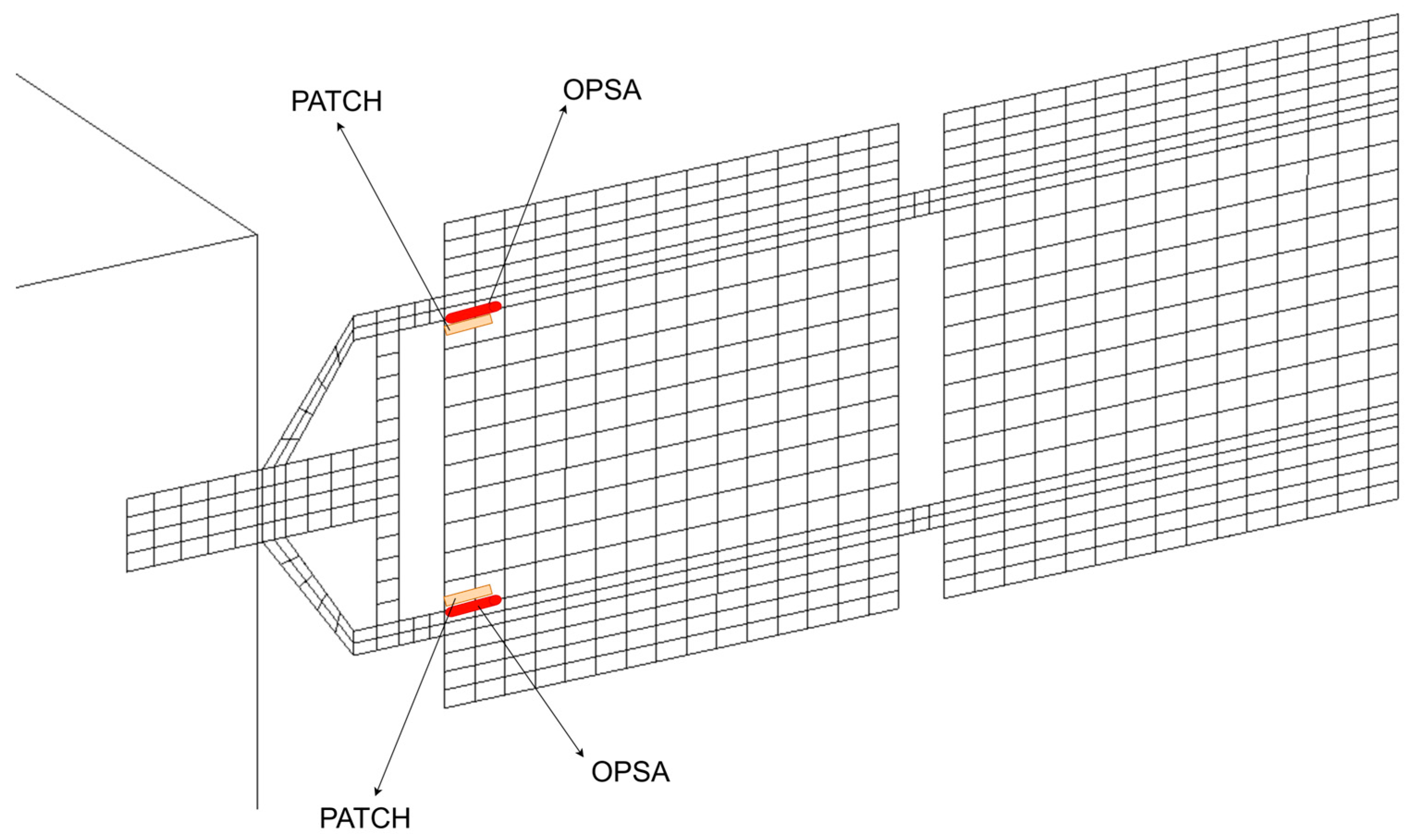
The positioning logic of piezoelectric sensors is based on the algorithm developed and tested in authors’ previous work [33]. In detail, piezo actuators/sensors are strategically placed in proximity to those locations experiencing higher structural deformations, corresponding to areas with highest MSE. The Modal Strain Energy (MSE)—defined as the amount of elastic energy stored in a finite element [40]—associated to the flexible appendages is computed by using the same finite element model used in the non-linear spacecraft simulator. The related MSE map (see Figure 11) is used to identify the locations of the elements whose change in mechanical properties have the major impact for the global dynamics of the system. The elements where to place the smart devices are retained based on a threshold on MSE density value (i.e. energy per element volume): only elements in up to green areas (in Figure 11), common to all three modes, are considered. The final actuator and sensor configuration is shown in Figure 12, for a total of two OPSA actuators and two piezo patch sensors for each solar panel. It should be noticed that such a placement aims at using the minimum number of devices on each panel to counteract the elastic vibrations deriving from the first three modal shapes of the satellite, i.e., not only bending but also torsional excitation. In the latter case, having two actuators symmetrically placed with respect to the y-axis allows to actuate them with opposite sign to address such deformation.
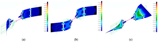
Figure 11.
Modal Strain Energy (MSE) density map (i.e. energy per element volume in ), colored from red (areas with higher MSE density) to blue (lowest MSE density): (a) 1st mode; (b) 2nd mode; (c) 3rd mode.
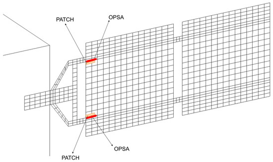
Figure 12.
Actuators and sensors position on the +y-axis solar panel. A symmetric configuration is implemented on the other solar array.
3.3.3. Platform Control: Bang-Bang Maneuver
To explore the vibration control issue in case of the innovative composite material, simulations including a simple attitude maneuver (bang-bang control) are proposed in this research. A bang-bang control, often used when the rotation of a spacecraft is controlled by thrusters, being an impulsive approach can indeed entail a significant excitation of structural modes. Nonetheless, being a time-optimal control, this approach allows the fastest re-orientation.
By way of illustration of the mentioned issue, an attitude maneuver has been simulated here to study the performance of the active control in damping out the remaining elastic vibrations. A simple bang-bang maneuver about the nadir-pointing axis (i.e., satellite z-axis) to reach a desired angle of is performed by way of illustration. By supposing the only actions on the spacecraft are those of the thrusters, the equation for the rotation for a rigid body along a prescribed axis can be written as
where is the inertia about the considered axis, is the torque to be applied, is the final instant of the maneuver, and is the Heaviside function. By integrating twice with respect to time, and by considering two thruster pulses, the needed torque to reach the desired angle can be obtained as
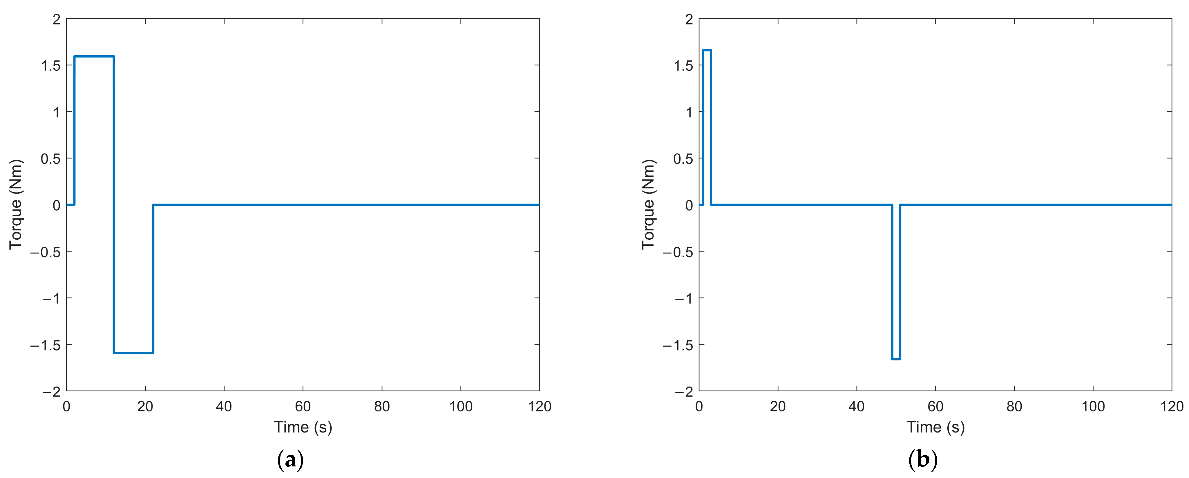
where is the pulse duration, and is the desired angle. Two maneuvers are simulated, as described in Equation (29), by varying the applied pulse and motion duration. The applied torques are illustrated in Figure 13. The two cases were chosen to have similar value of the applied torque, so as to have comparable initial excitation of the spacecraft flexible dynamics, with the aim of analyzing the control effectiveness for a fast maneuver (rate of 2.75°/s, with long pulses) and an agile one (rate of 1.1°/s, with short pulses).
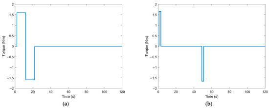
Figure 13.
Maneuvers: (a) Control A: very fast maneuver; (b) Control B: agile maneuver.
4. Results
The objective of this study is to examine the efficacy of the proposed AVC architecture on innovative and lightweight composite materials. In case of large space structures, a low value of structural damping can be regarded as an undesired condition (i.e., very flexible appendage) due to the persistence of noticeable elastic oscillations at the end of re-orientation maneuvers. Generally, after an attitude maneuver, a tranquilization time is indeed required to reach the desired pointing stability at the end of the motion. By using traditional control methods, the interaction between the elastic and rigid dynamics usually determines long tranquilization periods before the flexible displacements naturally damp out, especially for very fast motions (which are, however, increasingly required for Earth Observation applications). Therefore, vibration reduction systems are promising solutions to allow high performance operations while actively stiffening the structural appendages.
4.1. Simulation Cases
Based on the experimentally derived data, different damping conditions are hypothesized for the solar panel material. In particular, by observing Figure 7, a nominal damping = tan(δ) = 0.012 can be noticed, and—according to the standard deviation related to the tests—two worst cases values can be identified as = 0.022 (high damping case) and = 0.005 (low damping case). The values remain mostly constant in the temperature range reaching the glass transition temperature, after which the material starts to change its properties (i.e., “softening”) and the damping increases significantly. However, in this solar panel case study, only the temperature range below the transition temperature is considered, as explained in Section 3.
The performed simulation experiments are summarized in Table 6. In particular, twelve cases are considered: the maneuvers are repeated for three damping levels for each type of bang-bang control (please also refer to Section 3.3.3), for both passive (no active vibration control) and AVC cases.
Table 6.
Summary of simulated maneuvers.
4.2. Simulation Results
In this section, the main results from the simulated attitude maneuvers are introduced, while more details will be discussed in Section 5.
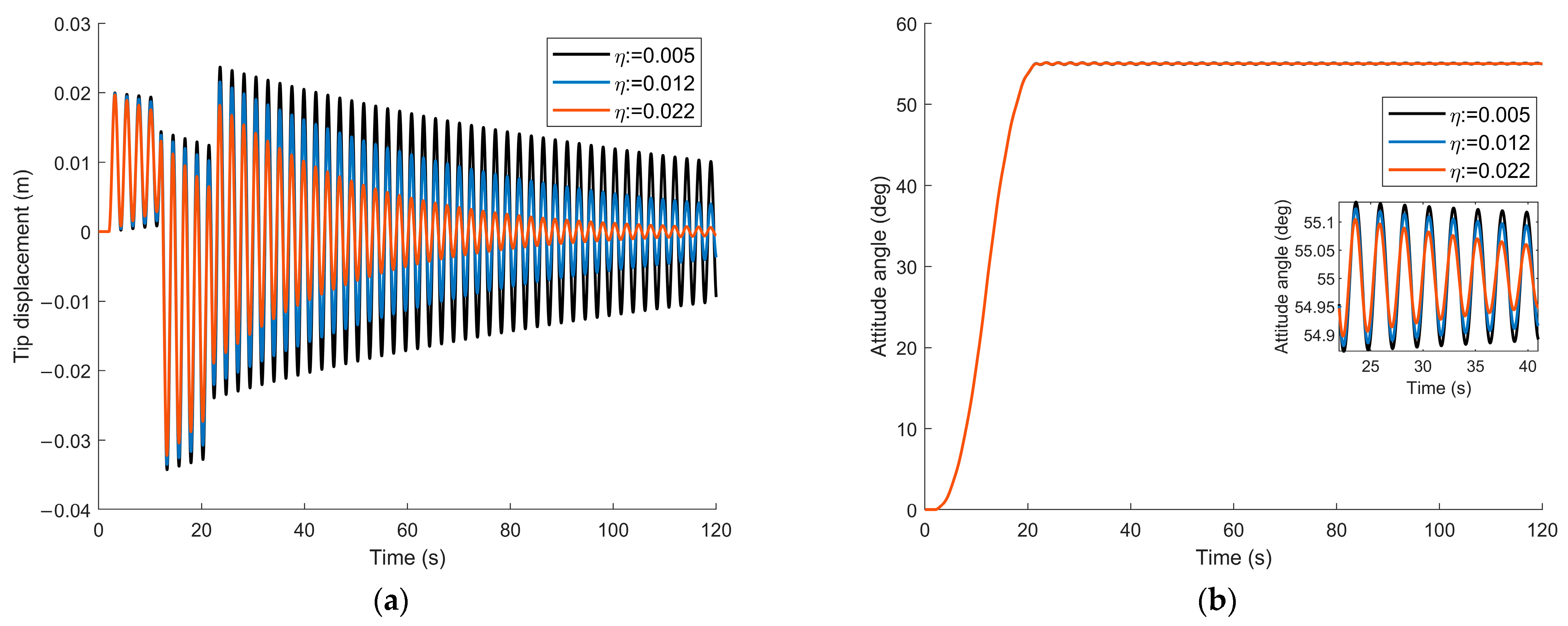
First, the system behavior without an active vibration control system is investigated. The time histories of the solar panel tip displacement with different values of damping are shown in Figure 14a for Control A and Figure 15a for Control B. In particular, the black lines indicate the elastic vibrations in the case of low damping (and, therefore, highest vibrations), while the blue and the red lines show the nominal and high damping cases, respectively. It can be noticed how the vibrations persist significantly during and after the attitude maneuvers. In detail, the tip displacements are derived by integrating the mathematical model presented in Equation (28), by pre-multiplying the output modal amplitudes by the structural modal shapes to obtain displacements in specific nodes of the structure, as described also in [36].

Figure 14.
Control A—Structural damping cases: (a) tip displacement; (b) attitude angle about nadir axis (i.e., satellite z-axis), and zoom on attitude perturbation due to coupling with elastic dynamics.

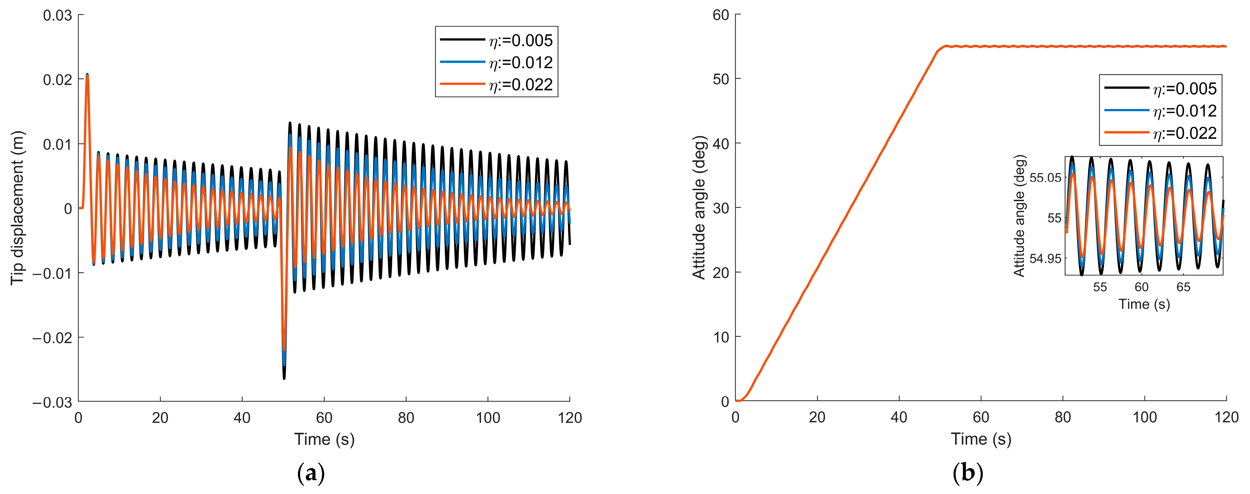
Figure 15.
Control B—Structural damping cases: (a) tip displacement; (b) attitude angle about nadir axis (i.e., satellite z-axis), and zoom on attitude perturbation due to coupling with elastic dynamics.
The satellite attitude angles are instead depicted in Figure 14b for Control A and Figure 15b for Control B. It should be noted that, even if the spacecraft is able to reach the target attitude in the desired time period, the panels elastic vibrations are noticeably affecting the final angle, by inducing oscillations which do not dampen out in the first minutes after the re-orientation. In particular, the spacecraft attitude angles are directly obtained by computing the state vector of the system, introduced in Equation (10), according to platform-level sensors with standard accuracy and measurement errors as in [41].
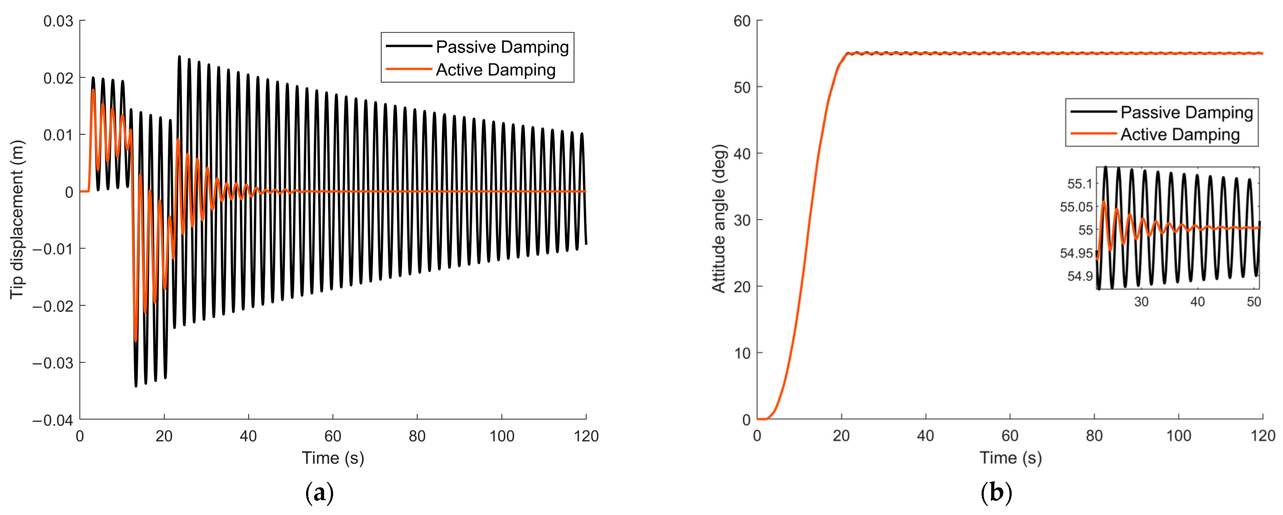
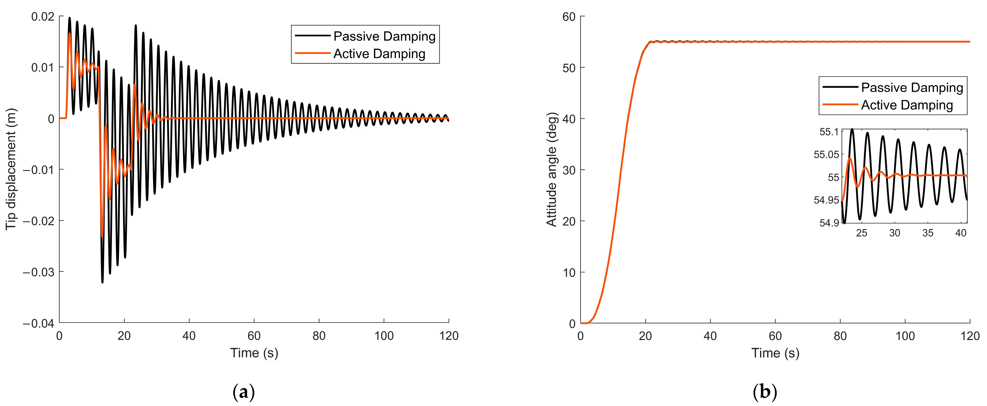
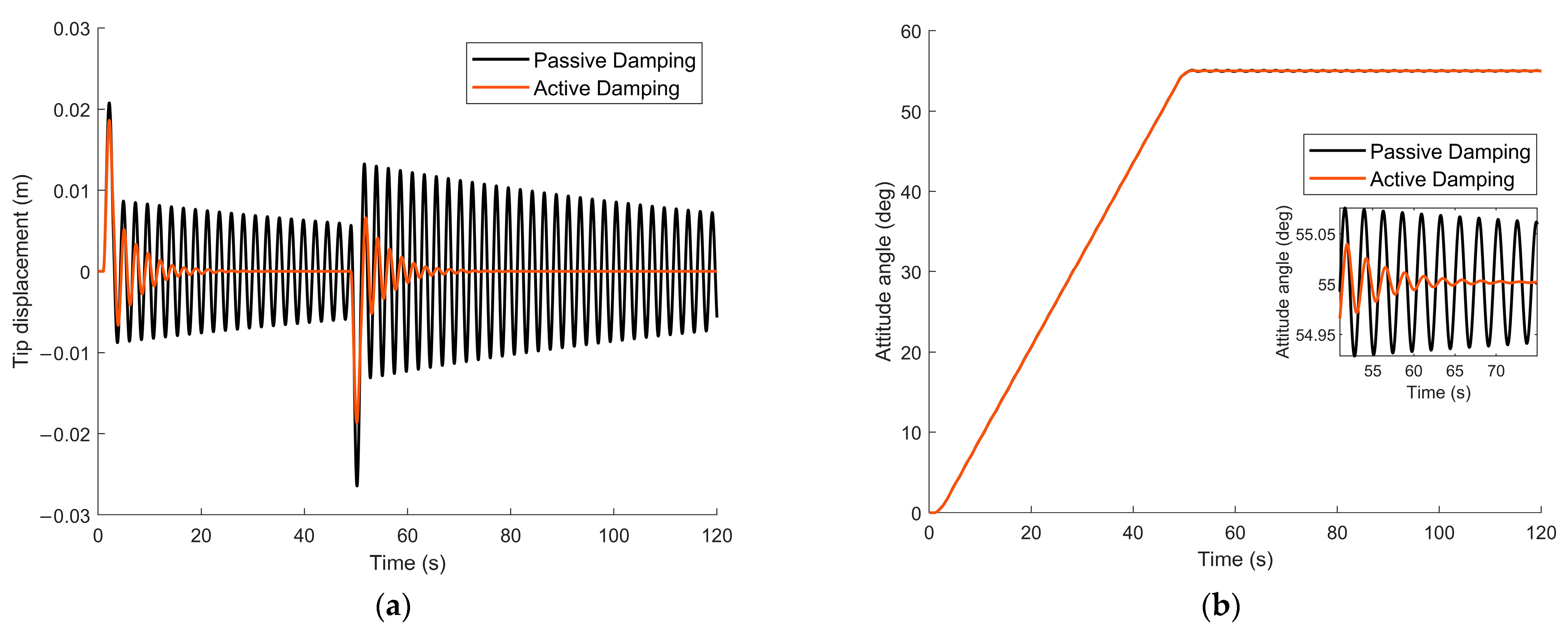
In a second phase, different cases of high and low damping are then analyzed in terms of improvement after applying the AVC control system. In particular, the most significant results are illustrated in Figure 16 and Figure 17 for Control A and Figure 18 and Figure 19 for Control B. The passive structure tip displacements are represented in black in Figure 16a, Figure 17a, Figure 18a and Figure 19a, while the tip displacements after applying the AVC strategy is depicted in red in the same pictures. A very good enhancement and vibration reduction can be observed in all the presented displacement time histories.
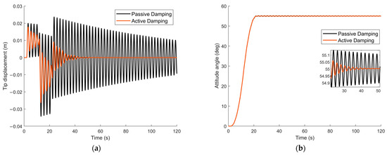
Figure 16.
Control A—Low damping—Simulation outcome: (a) tip displacement; (b) attitude angle about nadir axis (i.e., satellite z-axis), and zoom on attitude perturbation due to coupling with elastic dynamics.
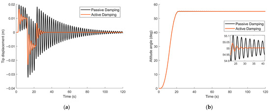
Figure 17.
Control A—High damping—Simulation outcome: (a) tip displacement; (b) attitude angle about nadir axis (i.e., satellite z-axis), and zoom on attitude perturbation due to coupling with elastic dynamics.

Figure 18.
Control B—Low damping—Simulation outcome: (a) tip displacement; (b) applied voltages.
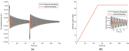
Figure 19.
Control B—High damping—Simulation outcome: (a) tip displacement; (b) applied voltages.
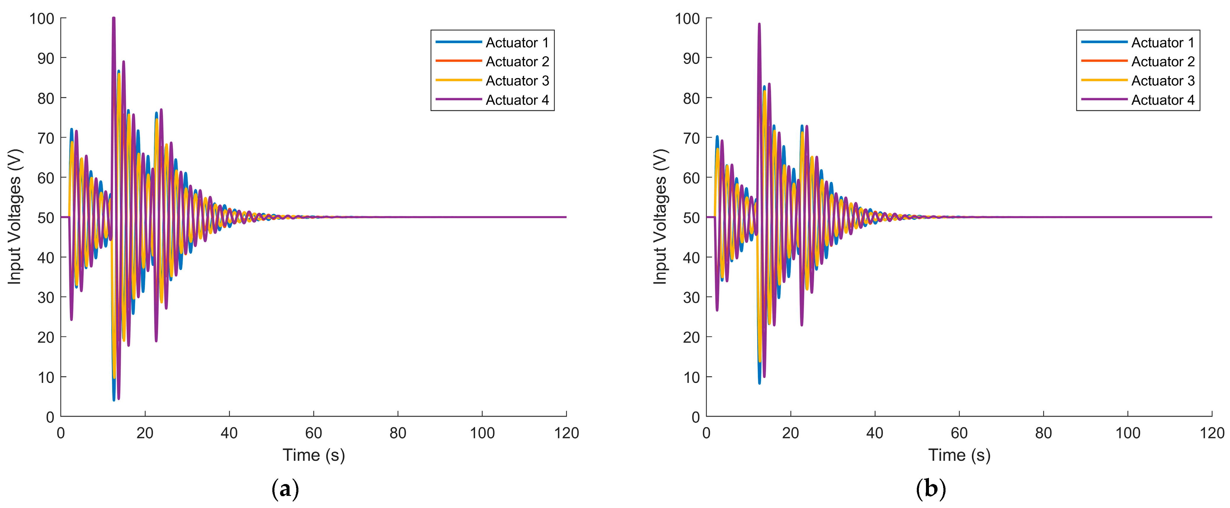
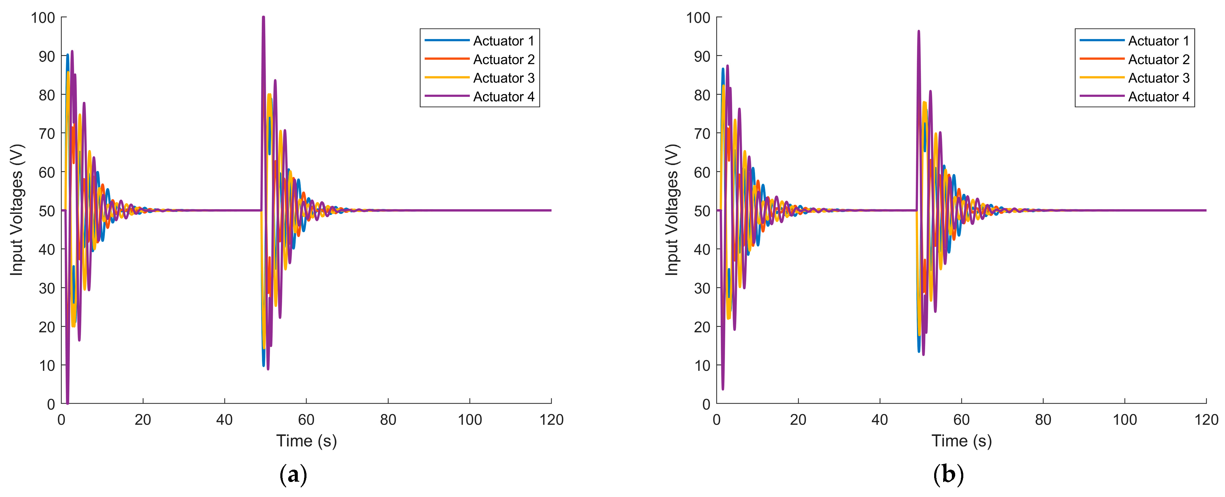
Finally, the actuators input voltages are also reported in Figure 20 and Figure 21. These quantities are computed based on Equation (26) for the two different attitude maneuvers. As expected, the voltage peaks have to be provided to the AVC system in correspondence with the thruster’s firings, while the structural appendages are more excited by the attitude control. In particular, a symmetric behavior of the actuators input voltage can be noticed, as the attitude maneuver notoriously induces an asymmetric bending of the solar panels in satellite systems.
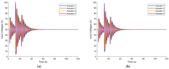
Figure 20.
Control A—Input voltage: (a) low damping; (b) high damping.
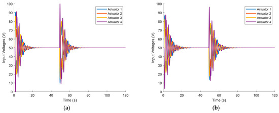
Figure 21.
Control B—Input voltage: (a) low damping; (b) high damping.
To estimate the effectiveness of the AVC system, an assessment of the damping ratio of the system with and without vibration reduction is presented here. Indeed, as Figure 14, Figure 15, Figure 16, Figure 17, Figure 18 and Figure 19 illustrate the elastic displacement at the tip of the panels, then, when the actuator works at the operating conditions listed in Table 4, the logarithmic decrement of the system with implemented active devices can be computed to evaluate the damping ratio ζ as follows:
Hence, Equation (31) is applied to the recorded tip displacement time histories, and the related results are reported in Table 7 and Table 8. A good enhancement of the structural damping capability can be clearly noticed when using the piezo actuators devices.
Table 7.
Damping coefficients: Control A.
Table 8.
Damping coefficients: Control B.
5. Discussion
It is evident that the proposed vibration control method is able to effectively damp the rigid–motion-induced flexible vibrations on the carbon-reinforced thermoplastic composite. This can be noticed both by observing the time histories of the tip displacement, and the derived damping coefficient in Table 7 and Table 8. In particular, only the displacement of one of the two solar arrays is here reported, due to symmetry reasons. The same applies to the actuators driving voltages, which will have the same modulus as the ones on the opposite panel.
Both agile maneuvers, indeed, cause relevant elastic oscillations in the order of a few centimeters, to the extent of producing noticeable effects on the attitude of the satellite at the end of the re-orientation. This is shown in the zoomed boxes in Figure 14, Figure 15, Figure 16, Figure 17, Figure 18 and Figure 19. It can be observed that, in the absence of an active control system, the satellite nadir angle can oscillate around the target value from (Control B, high damping case) to in the worst case (Control A, low damping case). Such errors can be considered as not in line with expected values for high-performance Earth Observation satellites, which also reach [20]. Moreover, another crucial aspect to be considered is the tranquilization time, that is the period needed to reach the desired pointing stability at the end of the maneuver (i.e., attitude remains fixed under a certain error threshold). In case of passive damping, very long tranquilization times are observed to reach a standard stability condition: 1 min in case of Control B and high damping, up to 6 min in the worst case of Control A and low damping. The need to wait such long times before starting scientific operations (such as image or data acquisition) is detrimental to performing such fast maneuvers. The AVC system is able to both counteract effectively the attitude error and significantly reduce the tranquilization time, up to 9 s (Control B, high damping) and 30 s (Control A, low damping), respectively.
A set of pragmatic factors has also been considered in this work to demonstrate that the method is suitable for practical implementation. To avoid the actuators being fed with a higher input voltage than their physical limit (which leads to suffering a condition of dielectric breakdown), saturation blocks are considered in to the control scheme. In Figure 20a and Figure 21a, the control channel is saturated for a few seconds, but this event does not jeopardize the effective damping capability of the active system. Moreover, it can be noticed the input voltages of the piezo actuators (see Figure 20 and Figure 21) are biased by a constant value of 50 V, which brings the positive/negative signal from the sensing system in the correct range [0, 100] V. When using piezoelectric stack actuators in vibration control, the devices are required to generate a displacement in a two-sided fashion, i.e., to extend and contract. However, most of such devices, due to piezoelectric properties, show a unipolar behavior and cannot be fed with negative voltage. Aside from using asymmetrically bipolar devices, some design alternatives exist to avoid imposing a constant input signal, such as modifying the device spring preload, using two piezo-stack in series, or an advanced solution such as the one proposed by Luo et al. [19] for a large space structure. However, it should be reminded that piezoelectrics generally show very limited current needs and low power consumption in low/medium frequency range [42], and the chosen configuration will also depend on the passive structure design and available space.
The architecture proposed here has a very limited impact on the composite passive structure, a minimum number of actuators and sensors being used, with limited mass in the order of a few tens of grams (as reported in Table 4 and Table 5), even if considering the stack L-shaped supporting structure. An additional advantage is the scalability of the system: the vibration suppression performance can be further improved if more than two actuators for each solar panel are considered. In this case, a trade-off between desired efficacy and mass/cost impact has to be considered according to the selected application.
6. Conclusions
As composite materials are increasingly being addressed attention in the aerospace sector, leading to lightweight, flexible, and high performing components, this paper assesses the performance of a piezoelectric-based active vibration control on an innovative carbon-reinforced thermoplastic (CF-PEEK) composite panel. In the first phase, the properties of the composite specimen are numerically and experimentally validated by simulating the material in Digimat environment, and performing three-point bending tests. As a result, the mechanical properties and damping characteristics of the CF-PEEK are derived and used to build a finite element model of the composite panel. The vibration suppression system is applied to an aerospace system subjected to rigid/flexible dynamics interaction: two solar panels equipped a satellite. A finite element model of the composite structure with integrated piezoelectric actuators and sensors is presented. This is used to perform re-orientation attitude maneuvers to assess the performance of the control system. This approach was shown to be able to relevantly dampen the elastic vibrations of the composite material, while reducing both the amplitude and the duration of the flexible oscillations.
This work highlights the need to address the problem of vibration control for innovative carbon-based materials for aerospace applications, as demonstrated by analyzing and experimentally evaluating the damping properties of a CF-PEEK specimen. Moreover, the current research proposes an effective active vibration control framework, based on an innovative piezoelectric configuration. Such architecture can easily be transferred to other applications by properly scaling the system and reconsidering the best placement and number of smart devices.
Future developments will include the improvement of the mathematical model of the actuators/sensors by including their nonlinear behavior (such as hysteresis and creep effects) directly in the FE formulation. Moreover, different types of hosting structures realized in composite material will be analyzed for vibration control purposes by using OPSA actuators. Lastly, it is worth mentioning that experimental tests will be performed to evaluate the effectiveness of system on a floating platform on a granite table, able to reproduce the attitude and flexible dynamics of the spacecraft, once the proposed vibration control devices are implemented on scaled solar panel structure realized in composite material.
Author Contributions
Conceptualization, F.A.; methodology, F.A., D.T., S.L. and P.G.; validation, F.A., S.L. and P.G.; formal analysis, F.A. and D.T.; investigation, F.A., D.T. and S.L.; writing—original draft preparation, F.A. and D.T.; writing—review and editing, F.A., D.T., S.L. and P.G.; supervision, S.L. and P.G.; funding acquisition, F.A., S.L. and P.G. All authors have read and agreed to the published version of the manuscript.
Funding
The work was partially financed by the European Union—NextGenerationEU (National Sustainable Mobility Center CN00000023, Italian Ministry of University and Research Decree n. 1033-17/06/2022, Spoke 11—Innovative Materials and Lightweighting). The opinions expressed are those of the authors only and should not be considered as representative of the European Union or the European Commission’s official position. Neither the European Union nor the European Commission can be held responsible for them. This research was partially funded by Sapienza University of Rome (Grant MA21916B865F6B61) to S.L.
Institutional Review Board Statement
Not applicable.
Informed Consent Statement
Not applicable.
Data Availability Statement
Not applicable.
Conflicts of Interest
The authors declare no conflict of interest.
References
- Ketner, G.L. Survey of Historical Incidences with Controls-Structures Interaction and Recommended Technology Improvements Needed to Put Hardware in Space; Pacific Northwest National Laboratory (PNNL): Richland, WA, USA, 1989.
- Miller, G.D.; Wykes, J.H.; Brosnan, M.J. Rigid-Body Structural Mode Coupling on a Forward Swept Wing Aircraft. J. Aircr. 1983, 20, 696–702. [Google Scholar] [CrossRef]
- Wu, J.; Ma, Y.; Wang, Z.; Yu, Z. Structurally Coupled Characteristics of Rotor Blade Using New Rigid-Flexible Dynamic Model Based on Geometrically Exact Formulation. Chin. J. Aeronaut. 2022, 35, 186–197. [Google Scholar] [CrossRef]
- Chen, Y.; Zhang, J.; Li, Z.; Zhang, H.; Chen, J.; Yang, W.; Yu, T.; Liu, W.; Li, Y. Manufacturing Technology of Lightweight Fiber-Reinforced Composite Structures in Aerospace: Current Situation and toward Intellectualization. Aerospace 2023, 10, 206. [Google Scholar] [CrossRef]
- Pérès, P.; Dupillier, J.M.; Defoort, B. Thermoplastic Composite Structures for Space Applications: Manufacturing Process Simulation. In Proceedings of the ECCM16—16th European Conference on Composite Materials, Seville, Spain, 22–26 June 2014. [Google Scholar]
- Jha, K.; Yeswanth, I.V.S.; Manish, D.; Tyagi, Y.K. Structural and Modal Analysis of PEEK-CF Composite for Aircraft Wing. In Proceedings of the Recent Trends in Engineering Design; Parey, A., Kumar, R., Singh, M., Eds.; Springer: Singapore, 2021; pp. 101–112. [Google Scholar]
- Yao, C.; Qi, Z.; Chen, W.; Zhang, C. Experimental Study on CF/PEEK Thermoplastic Fastener: Effects of Fastener Matrix Crystallinity and Fibre Content on the Strength of Single-Lap Joint. Compos. Part B Eng. 2021, 213, 108737. [Google Scholar] [CrossRef]
- Flanagan, M.; Grogan, D.M.; Goggins, J.; Appel, S.; Doyle, K.; Leen, S.B.; Ó Brádaigh, C.M. Permeability of Carbon Fibre PEEK Composites for Cryogenic Storage Tanks of Future Space Launchers. Compos. Part A Appl. Sci. Manuf. 2017, 101, 173–184. [Google Scholar] [CrossRef]
- Chadwick, A.; Dreher, P.; Petkov, I.; Nowotny, S. A Fibre-Reinforced Thermoplastic Primary Structure for Sounding Rocket Applications. In Proceedings of the SAMPE Europe Conference, Nantes, France, 17–19 September 2019. [Google Scholar]
- Lanouette, A.-M.; Potvin, M.-J.; Martin, F.; Houle, D.; Therriault, D. Residual Mechanical Properties of a Carbon Fibers/PEEK Space Robotic Arm after Simulated Orbital Debris Impact. Int. J. Impact Eng. 2015, 84, 78–87. [Google Scholar] [CrossRef]
- Lee, H.; Jang, J.; Kim, J.; Sang Kim, Y.; Cho, J.; Na Kim, M.; Tae Lee, J.; Hyuk Choi, W.; Man Song, J.; June Song, W.; et al. True Self-Reinforced Composites Enabled by Tuning of Molecular Structure for Lightweight Structural Materials in Future Mobility. Chem. Eng. J. 2023, 465, 142996. [Google Scholar] [CrossRef]
- Malozyomov, B.V.; Kukartsev, V.V.; Martyushev, N.V.; Kondratiev, V.V.; Klyuev, R.V.; Karlina, A.I. Improvement of Hybrid Electrode Material Synthesis for Energy Accumulators Based on Carbon Nanotubes and Porous Structures. Micromachines 2023, 14, 1288. [Google Scholar] [CrossRef]
- Gardie, E.; Paramasivam, V.; Dubale, H.; Tefera Chekol, E.; Selvaraj, S.K. Numerical Analysis of Reinforced Carbon Fiber Composite Material for Lightweight Automotive Wheel Application. Mater. Today Proc. 2021, 46, 7369–7374. [Google Scholar] [CrossRef]
- Gong, L.; Zhang, F.; Peng, X.; Scarpa, F.; Huang, Z.; Tao, G.; Liu, H.-Y.; Zhou, H.; Zhou, H. Improving the Damping Properties of Carbon Fiber Reinforced Polymer Composites by Interfacial Sliding of Oriented Multilayer Graphene Oxide. Compos. Sci. Technol. 2022, 224, 109309. [Google Scholar] [CrossRef]
- Xie, Y.; Huang, H.; Hu, Y.; Zhang, G. Applications of Advanced Control Methods in Spacecrafts: Progress, Challenges, and Future Prospects. Front. Inf. Technol. Electron. Eng. 2016, 17, 841–861. [Google Scholar] [CrossRef]
- Wang, W.; Xiang, Y.; Yu, J.; Yang, L. Development and Prospect of Smart Materials and Structures for Aerospace Sensing Systems and Applications. Sensors 2023, 23, 1545. [Google Scholar] [CrossRef]
- Heganna, S.S.; Joglekar, J.J. Active Vibration Control of Smart Structure Using PZT Patches. Procedia Comput. Sci. 2016, 89, 710–715. [Google Scholar] [CrossRef]
- Shevtsov, S.; Akopyan, V.A. Active and Passive Vibration Control of Aircraft Composite Structures Using Power Piezoelectric Patch-like Actuators. In Piezoceramic Materials and Devices; Springer: Berlin/Heidelberg, Germany, 2010; pp. 285–324. ISBN 978-1-60876-459-4. [Google Scholar]
- Luo, Y.; Zhang, X.; Zhang, Y.; Qu, Y.; Xu, M.; Fu, K.; Ye, L. Active Vibration Control of a Hoop Truss Structure with Piezoelectric Bending Actuators Based on a Fuzzy Logic Algorithm. Smart Mater. Struct. 2018, 27, 085030. [Google Scholar] [CrossRef]
- Qu, Z.; Zhang, G.; Meng, Z.; Xu, K.; Xu, R.; Di, J. Attitude Maneuver and Stability Control of Hyper-Agile Satellite Using Reconfigurable Control Moment Gyros. Aerospace 2022, 9, 303. [Google Scholar] [CrossRef]
- Irving, P.E.; Soutis, C. Polymer Composites in the Aerospace Industry, 2nd ed.; Woodhead Publishing: Sawston, UK, 2014. [Google Scholar]
- Laurenzi, S.; Casini, A.; Pocci, D. Design and Fabrication of a Helicopter Unitized Structure Using Resin Transfer Moulding. Compos. Part A Appl. Sci. Manuf. 2014, 67, 221–232. [Google Scholar] [CrossRef]
- Laurenzi, S.; Grilli, A.; Pinna, M.; De Nicola, F.; Cattaneo, G.; Marchetti, M. Process Simulation for a Large Composite Aeronautic Beam by Resin Transfer Molding. Compos. Part B Eng. 2014, 57, 47–55. [Google Scholar] [CrossRef]
- Tenax Teijin Limited. PEEK-HTA40. Available online: https://pdf.directindustry.it/pdf-en/toho-tenax-europe-gmbh/tenax-e-tpwf-peek-hta40/37818-827515.html (accessed on 11 August 2023).
- Tenax Teijin Limited. PEEK-HTS45. Available online: https://pdf.directindustry.com/pdf/toho-tenax-europe-gmbh/tenax-e-tpud-peek-hts45/37818-495585.html (accessed on 11 August 2023).
- Panchal, B. Classical Laminate Theory (CLT) and Its Use for Designing and Manufacturing of FRP Plates; D. J. Sanghvi College of Engineering: Mumbai, India, 2021. [Google Scholar]
- Li, J.; Yan, S.; Cai, R. Thermal Analysis of Composite Solar Array Subjected to Space Heat Flux. Aerosp. Sci. Technol. 2013, 27, 84–94. [Google Scholar] [CrossRef]
- Almehisni, R.; Al Naimat, F. Heat Transfer Influence of Solar Panel on Spacecraft. In Proceedings of the 2018 Advances in Science and Engineering Technology International Conferences (ASET), Abu Dhabi, United Arab Emirates, 6 February–5 April 2018; pp. 1–6. [Google Scholar]
- Rosato, D.; Rosato, D. Design Optimization. In Plastics Engineered Product Design; Rosato, D., Rosato, D., Eds.; Elsevier Science: Amsterdam, The Netherlands, 2003; pp. 46–160. ISBN 978-1-85617-416-9. [Google Scholar]
- Nashif, A.D.; Jones, D.I.G.; Henderson, J.P. Vibration Damping; Wiley: Hoboken, NJ, USA, 1991. [Google Scholar]
- Chen, J.; Gowayed, Y.; Moreira, A.; Flowers, G. Damping of Polymer Composite Materials for Flywheel Applications. Polym. Compos. 2005, 26, 498–508. [Google Scholar] [CrossRef]
- Monti, R.; Gasbarri, P.; Vetrano, F. Viscoelastic Damping Devices for Space Applications. In Proceedings of the International Operational Modal Analysis Conference—IOMAC 2009, Porto Novo, Italy, 4 May 2009. [Google Scholar]
- Angeletti, F.; Iannelli, P.; Gasbarri, P.; Sabatini, M. End-to-End Design of a Robust Attitude Control and Vibration Suppression System for Large Space Smart Structures. Acta Astronaut. 2021, 187, 416–428. [Google Scholar] [CrossRef]
- Preumont, A. Vibration Control of Active Structures; Solid Mechanics and Its Applications Book Series; Springer International Publishing: Cham, Switzerland, 2018; Volume 246, ISBN 978-3-319-72295-5. [Google Scholar]
- Wang, W.; Yang, Z. A Compact Piezoelectric Stack Actuator and Its Simulation in Vibration Control. Tsinghua Sci. Technol. 2009, 14, 43–48. [Google Scholar] [CrossRef]
- Callipari, F.; Sabatini, M.; Angeletti, F.; Iannelli, P.; Gasbarri, P. Active Vibration Control of Large Space Structures: Modelling and Experimental Testing of Offset Piezoelectric Stack Actuators. Acta Astronaut. 2022, 198, 733–745. [Google Scholar] [CrossRef]
- Nagashio, T.; Yamada, K.; Miyaji, K.; Kida, T. Optimal Static Output Feedback Control for Large Space Structures and Its Application to Local Control. Jpn. Soc. Aeronaut. Space Sci. Trans. 2005, 47, 1–8. [Google Scholar] [CrossRef]
- Balas, M.J. Direct Velocity Feedback Control of Large Space Structures. J. Guid. Control 1979, 2, 252–253. [Google Scholar] [CrossRef]
- Ikeda, M.; Koujitani, K.; Kida, T. Optimality of Direct Velocity and Displacement Feedback for Large Space Structures with Collocated Sensors and Actuators. IFAC Proc. Vol. 1993, 26, 495–498. [Google Scholar] [CrossRef]
- Zhou, Y.; Sun, Y.; Zeng, W. A Numerical Investigation on Stress Modal Analysis of Composite Laminated Thin Plates. Aerospace 2021, 8, 63. [Google Scholar] [CrossRef]
- Ankersen, F. Guidance, Navigation, Control and Relative Dynamics for Spacecraft Proximity Maneuvers. Ph.D. Thesis, Aalborg University, Aalborg, Denmark, 2010. [Google Scholar]
- Jordan, T.; Ounaies, Z.; Tripp, J.; Tcheng, P. Electrical Properties and Power Considerations of a Piezoelectric Actuator. MRS Proc. 1999, 604, 203. [Google Scholar] [CrossRef]


Disclaimer/Publisher’s Note: The statements, opinions and data contained in all publications are solely those of the individual author(s) and contributor(s) and not of MDPI and/or the editor(s). MDPI and/or the editor(s) disclaim responsibility for any injury to people or property resulting from any ideas, methods, instructions or products referred to in the content. |
© 2023 by the authors. Licensee MDPI, Basel, Switzerland. This article is an open access article distributed under the terms and conditions of the Creative Commons Attribution (CC BY) license (https://creativecommons.org/licenses/by/4.0/).