Abstract
To ensure the stability of the tunnel structure, this paper simulates the excavation process of shield tunneling in karst areas, and monitors the top of the arch, the bottom of the arch and the waist of the arch within the influence of the cave. It obtains the displacement and stress change laws under the influence of the upper cave and the lower cave. Finally, the main factors causing karst collapse in tunnels are explored through orthogonal tests. The results indicate that the displacement of the surrounding rock within the influence of the cave decreases and the stress increases. When the cavity and the tunnel reach the safety limit distance, the effect of the lower cavity on the stress around the tunnel is more obvious than that of the upper cavity. The results of the orthogonal test show that when the cavity is above the tunnel, the tunnel burial depth has the greatest influence on the stability of the surrounding rock; when the cavity is below the tunnel, the cavity height has the greatest influence on the stability of the surrounding rock.
1. Introduction
Karst collapse is a karst geological action and phenomenon in which the rock around a cave is damaged by deformation caused by external factors and eventually causes a collapse [1,2]. It is one of the most common geological hazards in karst areas [3]. China is a vast country with complex geology. According to statistics, the karst area in China could be up to 3.65 million km2, accounting for more than one-third of the national territory, and it is the country with the largest karst area in the world. The occurrence of karst subsidence accidents is also very common, having been widely seen in 22 provinces and regions, and is most common in the southern region, while serious karst disasters have also occurred in Hebei, Shandong, Liaoning and other places [4]. In China, the problem of karst collapse has become a problem that cannot be ignored in the process of modern construction. The situation of karst collapse is complex and diverse, and the geological hazards caused by karst collapse are universal [5,6,7,8]. It threatens people’s lives and property safety and causes significant economic loss, but also brings a lot of construction and operational problems for engineering construction [9,10]. Karst collapse is difficult to predict because of the complex causes of collapse and the following characteristics: territoriality, hiddenness, suddenness and mass occurrence [11]. In addition, with the steady progress of rail transit construction projects, the number of shield tunneling projects through karst areas is gradually increasing. Karst collapse is easily triggered by factors such as construction disturbance, construction precipitation and water inrush in karst areas [12,13,14]. The karst collapse induced by shield tunneling in karst strata is affected by the combination of stratigraphic structure, geological conditions, construction control and other factors, which makes its karst collapse mechanism complex, thus leading to the complexity and urgency of karst collapse prevention and control during construction [15,16].
Therefore, in karst areas, it is very important and difficult to maintain the stability of the tunnel’s surrounding rock. To resolve these difficult problems, investigations based on theoretical derivations, numerical simulations, and physics experiments have been conducted by many scholars [17,18,19,20]. Ma et al. [21] used the distinct lattice spring model (DLSM) to numerically investigate the effect of karst caves on tunnel stability. Numerical simulation demonstrated that the closer the cave was to the tunnel, the weaker the tunnel was under loading. The larger the cave, the weaker the tunnel and its surrounding rock mass. Zhang et al. [22] established a three-dimensional numerical model of the upper cavern, studied the influence of the shape of the cavern on the stability of the surrounding rock, and analyzed the change law of the stress field and displacement field of the surrounding rock during the tunnel excavation. Wang et al. [23] studied the law and degree of influence of karst cave span, high span ratio and filling degree on the safety thickness of karst cave rooves by numerical simulation and theoretical calculation and established a prediction model of the safety thickness of karst cave rooves. By means of mechanical analysis, simulation calculations and field tests, Song [24] studied the stability of cavities of different orientations and sizes on the tunnel envelope (displacement, stress) and support (axial force, bending moment). Mo [25] used similar model tests and numerical simulations to study the stability of the surrounding rock and considered the effects of different cavern locations, water pressure, surrounding rock, and spacing on tunnel stability.
In addition, other scholars have studied the stability of tunnels from other perspectives. Zhang et al. [26] proposed a ground stability evaluation and analysis system based on improved fuzzy comprehensive evaluation along the tunnel line in a karst area and a ground stability evaluation index system was established. Liu et al. [27] developed a numerical model involving an iterative process. This model can determine the optimal shield tunneling excavation velocity needed to minimize the disturbance to the karst cave stability and ensure the safety of tunnel construction in karst areas.
Although numerous scholars have studied the stability of tunnels in karst areas and a wide variety of karst collapse prediction models have been established, the main factors causing karst collapse vary due to different geological conditions, construction methods and other conditions. With the advancement of the Jinan rail transit construction project, the length of the shield tunnel through the karst area is gradually increasing, and the construction disturbance of the shield tunnel can easily induce the collapse of karst strata. Therefore, it is necessary to investigate the dynamic changes of karst in Jinan under the influence of tunnel construction.
This paper compares three kinds of engineering geology conditions: no cavern, upper cavern and lower cavern, and studies the change law of displacement and stress in the arch top, arch bottom and arch waist during the tunnel excavation. The orthogonal test method is used to develop the test scheme of cavern span, cavern height and tunnel burial depth, and the extreme difference analysis method is used to examine the sensitivity and influence law of the three parameters. The research results can provide an important construction reference and a basis for subsequent work.
2. Basic Theory
The safety thickness of rock strata for outburst prevention between the tunnel and the cavern, which is the minimum distance between the tunnel and the cavern, can be analyzed by reasonably simplifying rock strata for outburst prevention into an elastic beam plate [28]. Based on the strength theory, the formula for calculating the minimum safety thickness of the anti-surge rock column is derived by structural mechanics.
To facilitate the study, the following assumptions are made for karst tunnels:
- Ignore the arching effect of rock strata for outburst prevention and simplify rock strata for outburst prevention to a horizontal yielding elastic beam;
- The surrounding rock has good integrity, no obvious joints and cracks, and can be regarded as a homogeneous, continuous, isotropic elastic beam plate that can withstand tensile and compressive stresses;
- The pressure of karst filler, water pressure and self-weight of the rock beam are regarded as homogeneous loads acting directly on rock strata.
Simplify the rock strata between the tunnel and the cave as a solid support beam. The loads on the rock strata are mainly self-weight load of rock strata (γh), gravity loading of karst fill (ps), water pressure (pw), and ground stress (q). Figure 1 shows the simplified karst tunnel mechanics model.
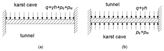
Figure 1.
Simplified mechanical model of tunnel and cave: (a) Upper cave; (b) Lower cave.
According to the theory of structural mechanics, when a solid supported beam is subjected to a uniform load, the maximum bending moment and the maximum shear force of the beam are calculated in Equations (1) and (2):
Then, the load is substituted in Equation (1). When the cavity is above the tunnel, the maximum bending moment and maximum shear force are calculated in Equations (3) and (4):
where M is the maximum bending moment on the rock beam, Q is the maximum shear force on the rock beam, ps is the gravity loading of karst fill, pw is the mean cavern water pressure, q is the equivalent vertical mean pressure converted from the surrounding rock pressure, γ is the heaviness of the rock, h is the safety thickness of the rock beam, B is the width of the rock beam and L is the length of the rock beam.
When the cavity is below the tunnel, the maximum bending moment and maximum shear force are calculated in Equations (5) and (6):
The equivalent vertical mean pressure q is calculated in Equations (7) and (8):
where S is the surrounding rock level; ω is the coefficient of span, when L < 5, i = 0.2, when 5 ≤ L < 14, i = 0.1.
For rectangular section beams, their flexural strength is verified in Equation (9) and their shear strength is verified in Equation (10):
where [σ] is the flexural strength of the rock and [τ] is the shear strength of the rock.
Substituting Equations (3) and (4) into Equations (9) and (10), respectively, the safe distance between the upper cavity and the tunnel is calculated in Equations (11) and (12):
Take the larger of the calculated values h1 and h2 of Equations (11) and (12) as the safe distance between the tunnel and the upper cavity.
Substituting Equations (5) and (6) into Equations (9) and (10), respectively, the safe distance between the lower cavity and the tunnel is calculated in Equations (13) and (14):
Take the larger of the calculated values h3 and h4 of Equations (13) and (14) as the safe distance between the tunnel and the lower cavity.
3. Project Case
There are a large number of karst caves in the interval from Jigang Xincun to Pengjiazhuang Station of Metro Line 2 in Jinan City, Shandong Province, China.
The karst in this area is mainly developed in strongly weathered limestone and a small amount is developed in medium-weathered limestone, strongly weathered marl and medium-weathered marl. Therefore, this paper selects the strongly weathered limestone as the research object.
After geological exploration, it is found that the karst in the area mostly consists of karstic fissures or small caves and locally fissured karst or karst holes, which are weakly developed karst. The height of karst caves is generally between 0.6 and 1.7 m.
The stability of karst in this area is good and no groundwater is exposed within the tunnel construction area. The seepage pressure of groundwater has little influence on the tunnel construction.
The distribution of the stratigraphy and various parameters are shown in Table 1.

Table 1.
Parameters of geotechnical and material.
4. Numerical Model
Using FLAC3D to build the model, the model size should be no less than four times the diameter of the tunnel [29], and also take into account the computational volume calculation time when the model is too large. In this model, half of the tunnel structure was taken according to the symmetrical nature. It is assumed that the interior of each stratum is homogeneously isotropic and that the different strata are parallel to each other.
The model size is 42 m in the direction along the tunnel, the model width is 30 m, and the distance from the bottom of the tunnel to the bottom of the model is 27 m.
The diameter of the tunnel is 6.4 m, the tube sheet uses C50 concrete, the thickness of the tube sheet is 0.2 m, only the displacement and stress changes of the surrounding rock of the initial tunnel support are considered, and the influence of the secondary support is not considered.
As shown in Figure 2. The model uses the Mohr–Coulomb constitutive model, and the support part uses the elastic model. The model is simplified to a homogeneous medium. According to the site conditions, the cavern is simplified to a small rectangular cavern.
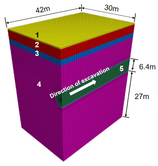
Figure 2.
Schematic diagram of the geological model: 1 is plain fill, 2 is Loess-like silty clay, 3 is silty clay, 4 is strongly weathered limestone, and 5 is the tunnel.
Based on the above model, a 15 m deep tunnel is established, with a cycle step of 3 m. The lining segment lags behind the excavation step, and each excavation cycle step can obtain the stress and displacement process of the tunnel at different stages. Changes in stress and displacement at the arch crown, arch bottom, and arch waist of the tunnel at 21 m were monitored under three different conditions: no karst cave, critical safety distance of the upper karst cave, and critical safety distance of the lower karst cave. The size of the karst cave is 2 m in span and 0.5 m in thickness, as shown in Figure 3 and Figure 4.
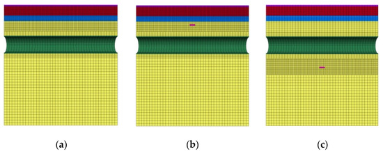
Figure 3.
Schematic diagram of the location of the tunnel and the cave: (a) Tunnel without caves; (b) Cave at critical safety distance above the tunnel; (c) Cave at critical safety distance below the tunnel.
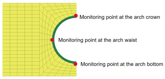
Figure 4.
Schematic diagram of the monitoring point at 21 m of the tunnel section.
5. Numerical Results
5.1. Dynamic Excavation Surrounding Rock Vertical Displacement
With the continuous advancement of the tunnel face, the soil displacement under the disturbance of shield excavation is also changing. After the completion of the tunnel excavation, the vertical displacement cloud diagram of the three cases of no karst cave, upper karst cave and lower karst cave are shown in Figure 5, Figure 6 and Figure 7, respectively.
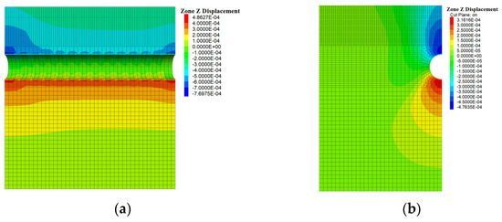
Figure 5.
Vertical displacement of the cavity-free tunnel: (a) Cross-section of the tunnel; (b) 21 m section of the tunnel. (Unit: m).
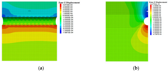
Figure 6.
Vertical displacement of the tunnel with a cavern above: (a) Cross-section of the tunnel; (b) 21 m section of the tunnel. (Unit: m).
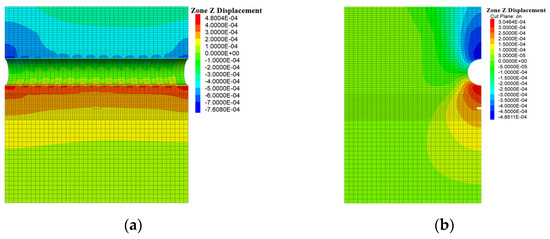
Figure 7.
Vertical displacement of the tunnel with a cavern below: (a) Cross-section of the tunnel; (b) 21 m section of the tunnel. (Unit: m).
As shown in Figure 5, Figure 6 and Figure 7, the vertical displacement mainly occurs in the vault and arch bottom of the tunnel after the tunnel excavation. Furthermore, the closer to the tunnel and the closer to the tunnel center line, the greater the vertical displacement value.
5.1.1. Comparison of Vertical Displacement between Upper Karst Cave and No Karst Cave
By monitoring the vertical displacement of the vault and arch bottom at 21 m during the excavation of the tunnel without a karst cave and with an upper karst cave the data shown in Figure 8 below were obtained.
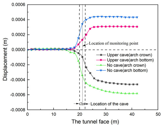
Figure 8.
Displacement curves of monitoring points.
The curve process of the tunnel excavation process can be divided into four parts: negative space effect section, positive space effect section, damping deformation section and rheological section [30]. The space effect section appears in the initial stage of tunnel excavation. The reason is that after the excavation of the tunnel, the surrounding rock loses the previous deformation constraint and the original equilibrium state changes. The rock makes the movement trend and then deforms and it affects the deformation of the rock mass at a deeper depth. At last, it reaches a certain depth.
The settlement value of the vault and the uplift of the arch bottom are about 0.1 mm. With the excavation of the tunnel, the settlement value of the vault and the uplift value of the arch bottom increase with the continuous advancement of the tunnel face. When the tunnel face is excavated to 42 m, the settlement value of the tunnel vault reaches 0.47 mm, and the uplift of the tunnel arch bottom is 0.3 mm. The tunnel excavation continues to advance backwards, and its value tends to be stable. At this time, the tunnel surrounding rock has stabilized.
From Figure 8, it can be seen that when the tunnel is excavated to 18 m, it has had a significant impact on the vertical displacement of the face at 21 m. When there is no karst cave, the vertical displacement of the arch is 0.05 mm at the 18 m top and 0.03 mm at the bottom; When there is a karst cave, the vertical displacement of the arch is 0.02 mm at the 18 m top and 0.02 mm at the bottom. The vertical deformation of the surrounding rock without karst cave development is greater than that with karst cave development, obviously. This is because the karst cave has a stabilizing effect on the surrounding rock of the excavation face.
When the tunnel is excavated to 25 m, the deformation of the arch bottom without a karst cave increases by 46.7% compared to that with a karst cave. When the tunnel is excavated to 35 m, the deformation of the arch top without a karst cave increases by 26.1% compared to that with a karst cave. Overall, the settlement of the surrounding rock at the bottom of the arch is smaller than that at the top of the arch.
5.1.2. Comparison of Vertical Displacement between Lower Karst Cave and No Karst Cave
Monitoring the vertical displacement of the vault and arch bottom at 21 m during the excavation of the tunnel without a karst cave and with a lower karst cave, as shown in Figure 9, showed that the influence of the upper and lower karst caves on the vertical displacement of the tunnel is not obvious at the critical safety distance.
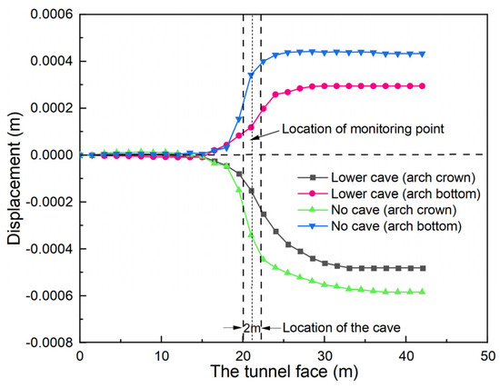
Figure 9.
Displacement curves of monitoring points.
5.2. Dynamic Excavation Surrounding Rock Horizontal Displacement
In the case of no cave, upper cave and lower cave, the horizontal displacement of the arch waist of the tunnel at the 21 m section was extracted. As shown in Figure 10, Figure 11 and Figure 12.
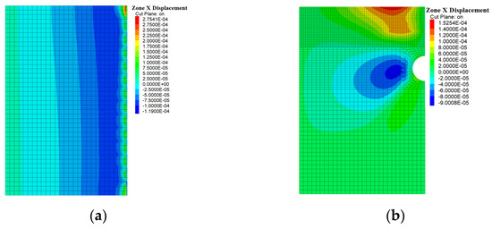
Figure 10.
Horizontal displacement of the cavity-free tunnel: (a) Cross-section of the tunnel; (b) 21 m section of the tunnel. (Unit: m).
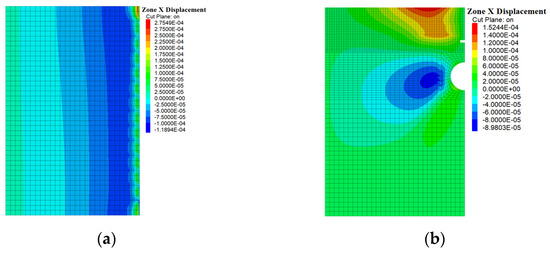
Figure 11.
Horizontal displacement of the tunnel with a cavern above: (a) Cross-section of the tunnel; (b) 21 m section of the tunnel. (Unit: m).
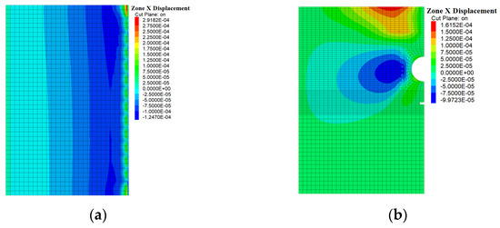
Figure 12.
Horizontal displacement of the tunnel with a cavern below: (a) Cross-section of the tunnel; (b) 21 m section of the tunnel. (Unit: m).
The specific horizontal displacement change process is shown in Figure 13. When the tunnel is excavated to 10 m, it has had a significant impact on the lateral deformation of the arch waist of the tunnel face at 21 m. When there is no karst cave development and when the karst cave development is in the upper and bottom part of the tunnel, the transverse deformation value at the haunch of the 10 m section is 0.007 mm, 0.005 mm, 0.005 mm, respectively.
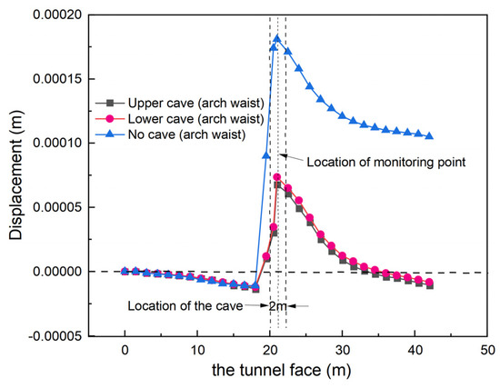
Figure 13.
Horizontal displacement curve of the monitoring point at the arch waist.
Compared to the effect of the karst cave on the tunnel vault, when the tunnel face is excavated to 18 m, the horizontal displacement of the arch waist monitoring point begins to develop inside the tunnel and it changes from inside to outside the tunnel at 34 m. When the tunnel is excavated to 21 m, the deformation value of the arch waist reaches its peak and the maximum horizontal displacement of the arch waist monitoring point is 0.18 mm without the cave case. The maximum horizontal displacement of the upper and bottom karst caves are 0.068 m and 0.074 mm, respectively. After that, the horizontal displacement of the monitoring point gradually decreases with the advance of the tunnel face. When the tunnel is excavated to 34 m, the displacement gradually tends to 0.01 mm.
This is due to the formation of a cavity in the tunnel caused by shield excavation. Under the pressure of surrounding rock, the arch waist begins to produce horizontal displacement to the inside of the tunnel, and reaches a peak at 21 m. Then, with the addition of shield lining segment structure, the horizontal displacement at the arch waist gradually tends to ease.
5.3. Dynamic Excavation Surrounding Rock Stress
The maximum principal stress and minimum principal stress of the vault and arch bottom at 9 m, 12 m, 15 m, 18 m, 21 m (karst cave position), 24 m, 27 m, 30 m and 33 m sections after excavation are extracted, respectively.
The values of the maximum principal stress are shown in Table 2. It can be seen that the maximum principal stress of the vault is greater than the maximum principal stress of the arch bottom. The maximum principal stress of the arch waist is four times the maximum principal stress of the vault and five times the maximum principal stress of the arch bottom.
Table 2.
Maximum principal stress at different cross-sectional locations in the tunnel.
To eliminate the influence of the edge effect of the model size, the data between the 15 m and 27 m sections were selected for analysis. It can be seen from Figure 14a that the maximum principal stress of the vault without the karst cave, and with upper and lower karst caves, gradually decreases with the increase of the tunnel section position. However, the maximum principal stress of the vault at each section is not much different. Under the condition of critical safety distance, the upper karst cave has no obvious influence on the maximum principal stress of the tunnel vault. The lower karst cave has no obvious effect on the maximum principal stress of the tunnel vault.
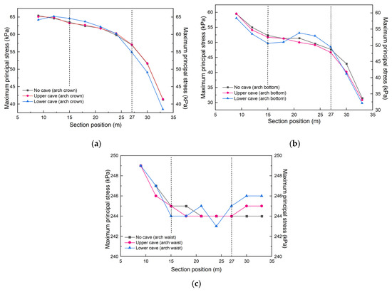
Figure 14.
Maximum principal stress curve: (a) Arch crown; (b) Arch bottom; (c) Arch waist.
It can be seen from Figure 14b that there was no significant difference in the maximum principal stress of the arch bottom under the condition of no karst cave and with the upper karst cave. It showed a gradually decreasing trend. The maximum principal stress of the arch bottom of the lower karst cave began to increase at the 18 m section, reached the peak value of 53.8 kPa at the 21 m section (karst cave location), and then the stress gradually decreased. The maximum principal stress recovered to the same level as that without the cavern at the 27 m section. It can be seen that the upper karst cave had no obvious effect on the tunnel arch bottom under the critical safety distance; the lower karst cave had an obvious influence on the tunnel arch bottom under the critical safety distance.
It can be seen from Figure 14c that the maximum principal stress without the karst cave and with the upper karst cave are basically maintained at about 244 kPa. The maximum principal stress of the arch waist of the lower karst cave began to increase at the 18 m section, reached the first peak of 245 kPa at the 21 m section (karst cave location), then decreased to 243 kPa at the 24 m section, and then gradually increased. It can be seen that the upper karst cave has no obvious influence on the maximum principal stress of the tunnel arch under the critical safety distance. The influence of the lower karst cave on the maximum principal stress of the tunnel arch under the critical safety distance is more obvious.
As Table 3 shows, the minimum principal stress of the arch bottom is greater than the minimum principal stress of the vault. The minimum principal stress of the arch waist is about 2.7 times that of the minimum principal stress of the vault. The maximum principal stress of the arch waist is about 2.1 times that of the maximum principal stress of the arch bottom.
Table 3.
Minimum principal stress at different cross-sectional locations in the tunnel.
Similarly, the data between the 15 m and 27 m sections were selected for analysis. As shown in Figure 15a, there is no significant difference in the minimum principal stress at the vault between the cavity-free and upper cavity cases. Compared with the no-cavity case, the minimum principal stress in the vault of the lower cavity increases by 2 kPa between 18 m and 21 m and decreases by 1 kPa at 24 m. When the distance between the cavity and the tunnel is the critical safety distance, the cavity above the tunnel has no obvious effect on the minimum principal stress in the arch, and the effect on the minimum principal stress in the arch of the cavity below the tunnel is obvious.
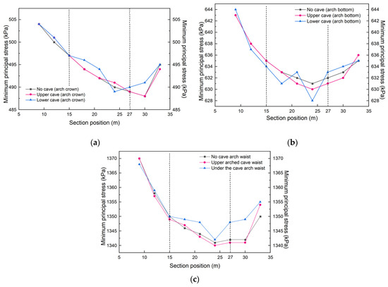
Figure 15.
Minimum principal stress curve: (a) Arch crown; (b) Arch bottom; (c) Arch waist.
As shown in Figure 15b, comparing the upper cavern with the no-cavern case, it can be seen that there is no significant difference in the minimum principal stress at the bottom of the arch. When there is a cavern in the lower part of the tunnel, the minimum principal stress at the arch bottom starts to increase at 18 m, it reaches a peak of 633 kPa at 21 m (cavern location), decreases to 628 kPa at 24 m, and then gradually increases. It can be seen that the influence of the lower cave on the minimum principal stress at the arch bottom is obvious.
As shown in Figure 15c, the minimum principal stress at the arch waist still does not change significantly when there is a cavern in the upper part of the tunnel. When there is a cavern in the lower part of the tunnel, the minimum principal stress at the arch waist starts to increase at 15 m. At 18 m, the minimum principal stress at the arch waist increases by 3 kPa compared to the tunnel without cavities, and at 21 m the minimum principal stress at the arch waist increases by 4 kPa, with no significant difference at 24 m compared to the arch waist of a tunnel without cavities. It can be seen that the down-lying cavern has a significant effect on the minimum principal stress in the arch waist of the tunnel.
From the above results, the maximum principal stress and the minimum principal stress of the tunnel are not significantly affected by the upper cavity in the state of safety critical distance. The influence of the lower cavity on the tunnel is obvious; the maximum and minimum principal stresses start to increase at 18 m. The stress increases the most at 21 m, then the influence of the cavern on the tunnel gradually decreases, and at 24 m the maximum and minimum principal stresses return to the level of the cavern-free tunnel, or even less than the cavern-free tunnel. The principal stresses in the tunnel reach their peak in the lower cavern influence range.
6. Orthogonal
The numerical simulation orthogonal test is carried out by FLAC3D to judge the safety thickness of an outburst-preventing rock pillar by whether the plastic zone of the tunnel and cavern is penetrated [31]. If the plastic zone is penetrated, the rock pillar is considered to be unstable; otherwise, it is considered that the thickness of the rock pillar is safe at this time, and then the distance between the karst cave and the tunnel is continuously optimized until it reaches the critical safety distance. Based on the existing model, the relative location of the karst cave and the tunnel are adjusted, assuming that the karst cave is located in the upper and lower part of the tunnel. By changing the location variable, the safety thickness rule of the top and bottom plate during karst tunnel excavation in the construction area is discussed. From Jigang Xincun Station to Pengjiazhuang Station, karst is mainly developed in strongly weathered limestone, and no groundwater is exposed. The orthogonal test adopts the scheme of three factors and four levels.
6.1. Orthogonal Test Protocol
In order to better explore the influence of the karst span on the safety thickness of an outburst-preventing rock pillar, the span range was expanded so that the span of the upper karst cave was between 0.5 m and 2.0 m, and the span of the lower karst cave was between 2.0 m and 5.0 m.
The thickness of the karst in this area ranges from 0.6 m to 1.7 m, so the value of the parameter karst thickness can be adjusted to from 0.5 m to 2.0 m.
According to the information from Jinan metro tunnels, the buried depths of the tunnels range from 14 m to 20 m.
The specific three factors and four levels are shown in Table 4.
Table 4.
The range of values of the orthogonal test.
6.2. Results of the Orthogonal Test
The orthogonal test design is based on the idea of equilibrium dispersion, using a combination of mathematical theories on the basis of the construction of an orthogonal table. There are 16 groups of data which are numerically simulated in the orthogonal table. By constantly adjusting the distance between the karst cave and the tunnel, the minimum unconnected zone appeared between the plastic zone of the karst cave and the plastic zone of the tunnel (see Figure 16). At this time, the distance between the karst cave and the tunnel is at the critical safety distance.
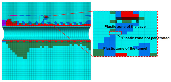
Figure 16.
Schematic diagram of plastic zone.
The orthogonal test scheme and the results of the safety thickness of the top plate of the upper karst cave are shown in Table 5.
Table 5.
The orthogonal test of the upper cave.
The orthogonal test scheme and the results of the safety thickness of the bottom plate of the lower karst cave are shown in Table 6.
Table 6.
The orthogonal test of the lower cave.
6.3. Data Analogy of Karst Collapse Induced Factors
Through the orthogonal test, the safety distance between the cave and the tunnel under different spans, heights and buried depths are obtained. In order to further analyze the correlations between the above three parameters and obtain the key parameters affecting the thickness of the top and bottom plates, range analysis is carried out on the orthogonal test data.
6.3.1. Range Analysis of Top Plate Safety Thickness
Range analysis is conducted on the orthogonal test data of the upper karst cave, and the results are shown in Table 7.
Table 7.
Range analysis of upper cave safety distance.
In Table 7, K1 represents that when the span of the cave is 0.5 m, the sum of all safety distances between the cave and the tunnel under the action of other influencing factors; k1 = K1/4. R is range, indicating the effect of the three defined influencing factors on the safety distance; the larger the range is, the more critical the factor plays in this simulation. Therefore, in the above range analysis table, it is not difficult to find that the three factors’ influences on the safe top plate thickness from large to small are: H > L > D.
The changing trend of tunnel safety thickness under the influence of various factors is shown in Figure 17.
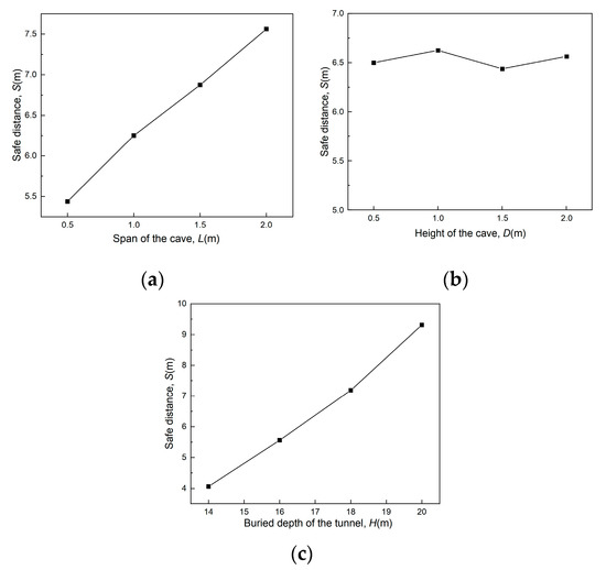
Figure 17.
Trend of safety distance of upper caves under the influence of various factors: (a) Span of the cave; (b) Height of the cave; (c) Buried depth of the tunnel.
As can be seen from Figure 17:
- The safety thickness of the top plate of the upper karst cave is positively correlated with the cave span, and it can be seen from the range analysis table that the cave span is an important factor affecting the safety thickness of the top plate.
- There is a weak correlation between the safety thickness of the top plate and the height of the karst cave.
- The safety thickness of the top plate of the upper karst cave is positively correlated with the tunnel burial depth, and it can be seen from the range analysis table that the tunnel burial depth is the most important factor affecting the safety thickness of the top plate.
After the above intuitive analysis, the next step is to estimate the magnitude of the error by conducting an analysis of variance and find the factors that can be disregarded.
The impact analysis of the F-test is shown in Table 8:
Table 8.
Influence analysis table of each factor.
According to the F distribution table, F0.05(3,4) = 6.59, F0.01(3,4) = 16.69; FH > FL > F0.01(3,4) = 16.69, the tunnel depth has the greatest influence on the test results, the span of the karst cave has a greater influence on the test results, FD < F0.05(3,4) = 6.59, and the karst cave height has little influence on the test results.
6.3.2. Range Analysis of Bottom Plate Safety Thickness
Range analysis is conducted on the orthogonal test data of the lower karst cave, and the results are shown in Table 9.
Table 9.
Range analysis of lower cave safety distance.
It can be seen from Table 9 that the three factors’ influence on the safety thickness of the bottom plate is in descending order: D > H > L.
The changing trend of safety distance under the influence of various factors is shown in Figure 18.
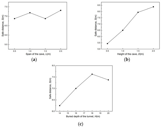
Figure 18.
Trend of safety distance of lower caves under the influence of various factors: (a) Span of the cave; (b) Height of the cave; (c) Buried depth of the tunnel.
As can be seen from Figure 18:
- There is a weak correlation between the safety thickness of the bottom plate and the cave span of the lower karst cave.
- The safety thickness of the bottom plate of the lower karst cave is positively correlated with the cave height, and it can be seen from the range analysis table that the cave height is an important factor affecting the safety thickness of the bottom plate.
- The safety thickness of the bottom plate of the lower karst cave is positively correlated with the tunnel burial depth, and it can be seen from the range analysis table that the tunnel burial depth has an important influence on the safety thickness of the bottom plate. Furthermore, with the increase of the tunnel burial depth, the safety distance tends to change gradually.
After that, the data were further analyzed. The impact analysis of the F test is shown in Table 10:
Table 10.
Influence analysis table of each factor.
According to the F distribution table, F0.05(3,4) = 6.59, F0.01(3,4) = 16.69; FL < F0.05 (3,4) = 6.59, showing that the span of the karst cave has the least influence on the test results. FD > F0.01(3,4) = 16.69, showing that the karst cave height has the greatest influence on the test results. F0.05(3,4) = 6.59 < FH < F0.01(3,4) = 16.69, showing that the tunnel burial depth has a great influence on the test results.
In summary, when the relative positions of the karst cave and the tunnel change, the main factors affecting the safety thickness of the outburst-preventing rock pillar also change. When the cave is located above the tunnel, the tunnel burial depth has the greatest influence on the roof safety distance, followed by the cave span, and the cave height has the least influence. When the cave is located below the tunnel, the height of the cave has the greatest influence on the safety distance of the roof, followed by the tunnel buried depth, and the span of the cave has the least influence.
7. Conclusions
This paper compares three working conditions around the tunnel: without cavities, with upper cavities and with lower cavities. The vertical and horizontal displacements of the tunnel are studied under three working conditions. The maximum principal stress and minimum principal stress are studied. Further, three influencing factors of caves and tunnels are selected in this paper: the span of the cave, the height of the cave, and the burial depth of the tunnel, and the degree of influence of the three factors on the stability of the surrounding rock is studied. The conclusions drawn from this study can be summarized as follows.
- Compared with no karst cave, both the upper and lower karst cave will make the vertical displacement of the tunnel vault and arch bottom around the cavity smaller and the horizontal displacement of the arch waist smaller.
- Compared with the cavity-free strata, there is no significant effect of the upper cavity on the maximum and minimum principal stresses in the tunnel at the safe critical distance state; under the influence of the lower cavity, the maximum and minimum stresses in the tunnel will peak.
- The three factors of tunnel burial depth, cavern span and cavern height were tested orthogonally to obtain the critical safety distances of the tunnel and cavern. The obtained data were subjected to extreme difference analysis, and the importance of the factors for the upper cavern safety distance was ranked from largest to smallest: tunnel burial depth > cavern span > cavern height, and the importance of the factors for the lower cavern safety distance was ranked from largest to smallest: cavern height > tunnel burial depth > cavern span.
Author Contributions
Conceptualization, G.H. and Y.W. (Yanyan Wang); methodology, P.X.; software, P.X.; validation, X.L. and Y.W. (Yixian Wang); formal analysis, P.X.; investigation, G.H.; resources, G.H.; data curation, Y.W. (Yanyan Wang); writing—original draft preparation, P.X.; writing—review and editing, H.B. and P.G.; visualization, P.X.; supervision, G.H. and P.G.; project administration, G.H.; funding acquisition, G.H. All authors have read and agreed to the published version of the manuscript.
Funding
This research was funded by the National Natural Science Foundation of China, grant number 42077249 and 42107082, the Natural Science Foundation of Anhui Province (CN), grant number 2108085QD166, Jinan Rail Transit Group Co. Ltd. Funded Project, grant number QT-ZF-2020-241, the Fundamental Research Funds for the Central Universities, grant number JZ2023HGTA0193 and JZ2023HGQA0094, the Opening Project of State Key Laboratory of Explosion Science and Technology (Beijing Institute of Technology), grant number KFJJ23-04M and KFJJ23-05M.
Institutional Review Board Statement
Not applicable.
Informed Consent Statement
Not applicable.
Data Availability Statement
Some or all data from the study are available from the corresponding author by request.
Conflicts of Interest
The authors declare that there is no conflict of interest regarding the publication of this article.
References
- Wang, X.; Xiao, Y.; Shi, W.; Ren, J.; Liang, F.; Lu, J.; Li, H.; Yu, X. Forensic analysis and numerical simulation of a catastrophic landslide of dissolved and fractured rock slope subject to underground mining. Landslides 2022, 19, 1045–1067. [Google Scholar] [CrossRef]
- Gu, Z.; Liu, Q.; Lu, Y.; Shi, Z.; Su, G.; Luan, D. Analysis and prevention of sinkhole collapses during the reconstruction and extension of Guang-Qing freeway, china. Environ. Earth Sci. 2016, 75, 788. [Google Scholar] [CrossRef]
- Zhou, W.; Lei, M. Summary editorial for karst hydrogeology: Advances in karst collapse studies. Environ. Earth Sci. 2018, 77, 803. [Google Scholar] [CrossRef]
- Zhang, L.; Zeng, X.; Yao, Y.; Liao, W. Review on karst collapse in China. Chin. J. Geol. Hazard Control. 2007, 18, 126–130. [Google Scholar] [CrossRef]
- Tang, Y.; Su, P.; Yu, H.; Du, Y. Study on Main Geological Problems of Railway Engineering in China Karst Area. Chin. J. Undergr. Space Eng. 2022, 18 (Suppl. S1), 296–304. [Google Scholar]
- Liang, Y.; Shen, H.; Gao, X. Review of research progress of karst groundwater in northern China. Bull. Geol. Sci. Technol. 2022, 41, 199–219. [Google Scholar] [CrossRef]
- Zhang, H.; Kang, X.; Wang, B.; Chai, J.; Zhou, C.; Cai, S.; Hou, X.; Huang, C.; Pan, X. Karst hydrogeological problems and countermeasures of a proposed railway in plateau slope area of southeast Yunnan. Carsologica Sin. 2022, 41, 718–727. [Google Scholar] [CrossRef]
- He, Q.; Tan, F.; Peng, Z.; Tao, L.; Jiao, Y.; Liu, S.; Peng, H. Genesis Analysis of Ground Collapse in Wuhan Based on 3D Geological Model. Front. Earth Sci. 2022, 10, 934452. [Google Scholar] [CrossRef]
- Liu, Y.; Zhu, J.; Liu, Q.; Yuan, A.; He, S.; Bai, Y. Mechanism Analysis of Delayed Water Inrush from Karst Collapse Column during Roadway Excavation Based on Seepage Transition Theory: A Case Study in PanEr Coal Mine. Energies 2022, 15, 4987. [Google Scholar] [CrossRef]
- Wang, X.; Lai, J.; He, S.; Garnes, R.S.; Zhang, Y. Karst geology and mitigation measures for hazards during metro system construction in Wuhan, China. Nat. Hazards 2020, 103, 2905–2927. [Google Scholar] [CrossRef]
- Xu, J.; He, J.; Zhang, L. Collapse prediction of karst sinkhole via distributed Brillouin optical fiber sensor. Measurement 2017, 100, 68–71. [Google Scholar] [CrossRef]
- Yang, F.; Lin, H.; Shen, L.; Yan, A.; Wu, Y. Water Inrush Mechanism of Karst Collapse Column in Coal Seam Floor Based on a Variable Mass Seepage Mechanical Model. Geofluids 2022, 2022, 8148203. [Google Scholar] [CrossRef]
- Xue, F.; Cai, M.; Wang, T.; Zhao, T. Characteristics of karst cave development in urban karst area and its effect on the stability of subway tunnel construction. Adv. Civ. Eng. 2021, 2021, 8894713. [Google Scholar] [CrossRef]
- Li, S.; Xu, Z.; Huang, X.; Lin, P.; Zhao, X.; Zhang, Q.; Yang, L.; Zhang, X.; Sun, H.; Pan, D. Classification, geological identification, hazard mode and typical case studies of hazard-causing structures for water and mud inrush in tunnels. Chin. J. Rock Mech. Eng. 2018, 37, 1041–1069. [Google Scholar]
- He, G.; Luo, X.; Fan, X.; Zhang, Y. Analysis on Karst Development Laws of Tunnels Based on the Markov Random Field. Modern Tunn. Technol. 2019, 56, 56–64. [Google Scholar] [CrossRef]
- Zhang, C.; Zhang, D.; Wang, M.; Li, Q.; Liu, S. Catastrophe mechanism and control technology of ground collapse induced by urban tunneling. Rock Soil Mech. 2010, 31 (Suppl. S1), 303–309. [Google Scholar]
- Chen, H.W.; Sha, C. Stability analysis of surrounding rock and treatment structures in superlarge karst cave of naqiu tunnel. Adv. Civ. Eng. 2018, 2018, 4842308. [Google Scholar] [CrossRef]
- Huang, J.; Wang, H.; Zhou, L.; Zhu, Z.; Deng, Z.; Deng, A. Analysis of stress intensity factor for a crack emanating from elliptical hole subjected to compressive stress and shear stress. Theor. Appl. Fract. Mech. 2022, 120, 103413. [Google Scholar] [CrossRef]
- Li, F.; Hu, Z.; Zhang, Y.; An, X.; Ren, X. Tunnel surrounding rock stability analysis based on geological condition reconstruction and karst development prediction. Arab. J. Geosci. 2022, 15, 1533. [Google Scholar] [CrossRef]
- Zhang, C.; Fu, J.; Yang, J.; Ou, X.; Ye, X.; Zhang, Y. Formulation and performance of grouting materials for underwater shield tunnel construction in karst ground. Constr. Build. Mater. 2018, 187, 327–338. [Google Scholar] [CrossRef]
- Ma, J.; Guan, J.; Duan, J.; Huang, L.; Liang, Y. Stability analysis on tunnels with karst caves using the distinct lattice spring model. Undergr. Space 2021, 6, 469–481. [Google Scholar] [CrossRef]
- Zhang, L.W.; Fu, H.; Wu, J.; Zhang, X.Y.; Zhao, D.K. Effects of karst cave shape on the stability and minimum safety thickness of tunnel surrounding rock. Int. J. Geomech. 2021, 21, 04021150. [Google Scholar] [CrossRef]
- Wang, W.; Gao, S.; Liu, L.; Wen, W.; Li, P.; Chen, J. Analysis on the safe distance between shield tunnel through sand stratum and underlying karst cave. Geosystem Eng. 2019, 22, 81–90. [Google Scholar] [CrossRef]
- Song, Z. Research on the influence of concealed karst caverns upon the stability of tunnels and its support structure. Chin. J. Rock Mech. Eng. 2006, 2006, 1296. [Google Scholar]
- Mo, Y. Stability Research on High Water Pressure Filled Karst Caves Tunnel. Ph.D. Thesis, Southwest Jiaotong University, Chengdu, China, 2009. [Google Scholar]
- Zhang, K.; Zhou, Z.; Chen, S. Stability Assessment of Ground Surface along Tunnels in Karst Terrain Using Improved Fuzzy Comprehensive Evaluation. Adv. Civ. Eng. 2021, 2021, 5523668. [Google Scholar] [CrossRef]
- Liu, Z.; Ming, W.; Li, J.; Zhou, C.; Zhang, L. Numerical prediction of the optimal shield tunneling strategy for tunnel construction in karst regions. PLoS ONE 2021, 16, e0252733. [Google Scholar] [CrossRef]
- Guo, J. Study on Against-Inrush Thickness and Waterburst Mechanism of Karst Tunnel. Ph.D. Thesis, Beijing Jiaotong University, Beijing, China, 2011. [Google Scholar]
- Zheng, G.; Du, Y.; Diao, Y.; Deng, X.; Zhu, G.; Zhang, L. Influenced zones for deformation of existing tunnels adjacent to excavations. Chin. J. Geotech. Eng. 2016, 38, 599–612. [Google Scholar] [CrossRef]
- Zhao, M.; Xu, R.; Xu, X. Deformation Analysis and Monitoring of Surrounding Rock during Full-face Excavation of Tunnel in Karst Regions. J. Tongji Univ. (Nat. Sci.) 2004, 2004, 866–871. [Google Scholar]
- Pei, L.; Qu, B.; Qian, S. Uniformity of slope instability criteria of strength reduction with FEM. Rock Soil Mech. 2010, 31, 3337–3341. [Google Scholar]
Disclaimer/Publisher’s Note: The statements, opinions and data contained in all publications are solely those of the individual author(s) and contributor(s) and not of MDPI and/or the editor(s). MDPI and/or the editor(s) disclaim responsibility for any injury to people or property resulting from any ideas, methods, instructions or products referred to in the content. |
© 2023 by the authors. Licensee MDPI, Basel, Switzerland. This article is an open access article distributed under the terms and conditions of the Creative Commons Attribution (CC BY) license (https://creativecommons.org/licenses/by/4.0/).