Abstract
Digital twins are used to replicate the behavior of physical systems, and in-vehicle networks can greatly benefit from this technology. This is mainly because in-vehicle networks circulate large amounts of data coming from various sources such as wired, or in some cases even wireless, sensors that are fused by actuators responsible for safety-critical tasks that require careful testing. In this work, we build a laboratory in-vehicle network that mimics a real vehicle network in regards to wire length, number of stubs and devices that are connected to it. The Controller Area Network (CAN), which is still the most popular communication bus inside cars, is used as a network layer. Using models defined in MATLAB for various subsystems, e.g., Anti-lock Braking System (ABS), Powertrain and Electric Power-Steering, deployed on automotive-grade microcontrollers, we evaluate the in-vehicle bus digital twin by providing realistic inputs and recording and reproducing in-vehicle network traffic. The experimental results showed good correlation between the output of the implemented digital twin and the data collected from an actual car.
1. Introduction and Motivation
During the last two decades, vehicles evolved towards software-driven objects, requiring a large number of Electronic Control Units (ECUs) that communicate over intricate in-vehicle networks. This evolution is based on the industry’s need to develop new automotive functions, e.g., adaptive cruise control, or to digitize existing functions, e.g., steer-by-wire. As confirmed by recent studies related to automotive trends [1], the near future will bring even more hardware and software updates to reach a new milestone for autonomous and connected cars. Thus, the number of threats and the magnitude of risks will increase as well. This calls for the study of automotive systems that implement specific functions at the vehicle level using simulations [2], models [3] or digital twins [4].
The digital twin concept defines a virtual counterpart realized as a prototype of a real product or process. The idea originates from the Florida Institute of Technology in the early 2000s [5]. The interpretation from the International Council on Systems Engineering (INCOSE) organization defines a digital twin as a high-fidelity model of the system [6]. There can be various levels of digital twins, starting from pre-digital twins to adaptive or intelligent digital twins that exchange more or less data with their physical twins or make use of reinforced learning [7].
Initially proposed and used in manufacturing processes [8], recent studies also evaluated the development of digital twins for physical automotive systems. One such study verified outputs of MATLAB models, i.e., the digital twin of a vehicle function, compared to real data extracted from the Controller Area Network (CAN) bus of the Toyota Prius test vehicle in the context of vehicle dynamics [9]. This work integrated several types of vehicle models in MATLAB in order to create the digital twin, i.e., single-track model, two track model, multi-body vehicle model and tire models. In the light of such works, given the trend of using digital twins for automotive systems or functions, our goal here is to explore the digital twin of a real vehicle CAN bus.
For defining our digital twin, we will use several embedded boards that implement specific models, connected to a Controller Area Network (CAN) bus from a real vehicle as shown in Figure 1. On each embedded board, we integrate a specific MATLAB model that receives input signals from the CAN bus and provides outputs that are computed based on those inputs (according to the system model). We analyze the wiring diagram handbook of the real car to determine the ECUs that communicate on the CAN bus and the vehicle functions realized by these ECUs. We give more details regarding the real CAN network in the forthcoming sections. One specific use case of the digital twin is in analyzing the effects of cyberattacks as we argue at the end of the experimental section. From a security standpoint, there are many CAN vulnerabilities shown by research works [10,11] as well as more recent attacks on real vehicles [12]. Thus, designing security countermeasures is a prime demand, and a digital twin can be immediately used to test new proposals.
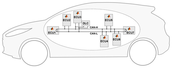
Figure 1.
Overview of the in-vehicle network that we model in CarTwin.
The contributions of our work, i.e., CarTwin—the digital twin of a real car, can be summarized as follows:
- 1.
- We use fine-grained details of a real vehicle CAN network, such as wire lengths, stub lengths, the number of nodes communicating on the bus and the real-world information that is sent on the network;
- 2.
- We use MATLAB models to implement ECU functionalities related to braking (Anti-lock Brake System), seat-belt status and seat position checks for airbag deployment (Restraints Control Module), remote keyless actions (Remote Function Actuator), entertainment and multimedia (Accessory Protocol Interface Module), wheel steering (Power Steering Control Module), engine and transmission controls (Powertrain Control Module) and the information presented to the driver (Instrument Panel Cluster);
- 3.
- We implement a tool in a high-level language that provides signal inputs to the models and records the CAN traffic from the bus, making the digital twin easy to use for experimental purposes.
The rest of the paper is structured as follows. In Section 2, we provide details related to CAN bus communication and the related work on digital twins and CAN buses. After that, within Section 3, we detail the characteristics of the real vehicle CAN network that we use as a basis for CarTwin. In Section 4, we detail the MATLAB Simulink models for each of the ECUs that share the CAN network, while in Section 5, we give the technical details for implementing the digital twin. Specific measurements from the experimental setup are depicted in Section 6, whilst Section 7 holds the conclusion of our work.
2. Background and Related Work
In this section, we discuss some background on CAN buses and related works on digital twins.
2.1. Background of the CAN Bus
Due to its cost efficiency and reliability under harsh conditions, the Controller Area Network (CAN) has been widely used since the 1990s in road vehicles as a data distribution interface between Electronic Control Units (ECUs), sensors and actuators. More recently, the CAN specifications were extended by Bosch to support higher payload and data rates as CAN-FD. The CAN protocol and its extension, CAN-FD, have been standardized by ISO (International Organization for Standardization) under the ISO-11898 standard [13,14]. A newer generation called CAN-XL, which will support even higher payloads and bit-rates that allow tunneling of Ethernet packets, will arrive soon. This proves that the CAN bus will survive in its newer embodiment, CAN-FD or CAN-XL, in future in-vehicle networks.
CAN is an asynchronous serial communication protocol that requires information to be transmitted using dominant, i.e., logical ’0’, or recessive, i.e., logical ’1’, bits. A twisted pair of wires denoted as CANH (CAN High) and CANL (CAN Low) with a termination of 120 Ω on both sides defines the CAN bus physical layer. The physical network supports the connection of multiple nodes that can transmit or receive frames with a pre-defined structure following the specifications defined by the CAN standard included in ISO-11898-1 [13]. The CAN nodes communicate on the physical bus using a CAN controller, usually embedded as part of a microcontroller, and a CAN transceiver. The CAN controller has two lines for communicating with the transceiver, called TX and RX. The RX line reflects the state of the physical bus converted by the transceiver from a differential voltage between CANH and CANL to a logical state, while the TX interface is used by nodes to transmit bits via the CAN transceiver on the physical bus. Each node can start communicating whenever the bus is idle, and if more than one node is trying to transmit data, all transmitters have to follow the arbitration procedure for the CAN bus, during which the node sending the frame with the highest priority wins.
There are four specific types of frames defined on the CAN bus: data frames used to transfer data, remote frames used to request a data frame, overload frames signaling an overload condition and error frames signaling an error was detected.
The CAN data frame is structured in different bit fields, which are defined according to the ISO-11898-1 [13] standard. Each frame transmission starts with the SOF (start of frame) bit, which is always dominant because the bus state is recessive when the bus is idle. It is followed by the arbitration field, which contains the frame identifier, i.e., ID, and will determine the node that wins the arbitration part. The ID is followed by the RTR (remote transmit request) bit, which, if recessive, it requests frame transmission from the genuine sender (remote frame), and if dominant, it means the data frame is transmitted by the sender (normal frame). The node that wins arbitration continues sending the control field, which starts with the IDE bit that is dominant for standard identifiers and recessive for extended identifiers. For standard frames, the control field contains a reserved bit that is always dominant and the number of data bytes carried by the frame, followed by the data field with the actual frame content called DLC. After the data field, the CRC field follows, and it is used by receivers to check the integrity of the received header and frame data. Then, the ACK field follows, which is used by the receivers to confirm the correct reception of the frame by transmitting a dominant bit over the recessive bit sent by the frame transmitter. Both CRC and ACK fields have a bit delimiter, i.e., DEL, that is always recessive. The frame ends with an EOF (end of frame) field of seven recessive bits. The remote frame has a similar structure with the data frame, except that it does not transmit data bytes, so it has an empty data field. The frame structure for a CAN data frame is depicted in Figure 2.
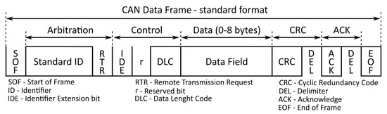
Figure 2.
Overview of the standard Controller Area Network (CAN) frame format.
2.2. Related Work
Since the CAN specification published by Bosch has been standardized, there have been many research papers addressing various topics related to it. The first studies were focused on the message scheduling [15,16] and response times due to message arbitration or error frames [17]. They were followed by proposals, such as TT-CAN [18] and CANOpen [19] that address its possible extensions so it can be adopted to other applications or updates to its original specification [20,21], with the goal to improve its communication bandwidth. Due to the increasing need for more data bytes in the message frames and faster communication between nodes, the automotive industry together with Bosch have published a newer version of CAN called CAN-FD (flexible data-rate) [13,14]. This extension proves that CAN is going to remain present in cars in the long run.
There were practical implementations of digital twins a few years after the concept was proposed [5], mainly in manufacturing processes as a basis for product lifecycle management [8]. Considering that digital twins represent an authentic copy of the real physical object with regards to specific properties, monitoring and diagnosing digital twins can reveal solid information, helpful for monitoring the real physical object behavior under certain conditions or stimuli. Digital twin frameworks and designs have been proposed by research works for a broad area of use cases, such as cyber-physical systems production [22,23], aerospace machining [24], drilling wells for the oil and gas industry [25], Internet of Things with 5G/6G networks [26] or even for healthcare services [27]. Automotive system digital twin proposals have emerged during the last couple of years from simulations of brake systems [28] to battery systems [29] and wiring harnesses [30]. A recent study provided details regarding the development and implementation of a digital twin architecture for an autonomous driving simulation [31]. Hence, our proposal from this work is a car twin with a real vehicle network defined by the wiring harness and monitored data as a digital twin.
From a security standpoint, authors from [32] described and detailed industrial control system testbeds, compared and evaluated existing datasets and reported which intrusion detection systems perform best. Furthermore, recent works proposed digital twin designs for evaluating privacy enhancement in automotive [33], prediction of cybersecurity incidents [34] and protection of critical infrastructure for intelligent transport systems [35]. Since none of the existing CAN standards propose any security requirements, the CAN bus is exposed to threats, so there are numerous research topics and proposals in this area. Thereby, the automotive industry requires vehicle manufacturers to embed rolling counters and message authentication codes inside the data field of the CAN frames that carry safety-critical data according to the AUTOSAR Secure On-board Communication standard [36].
3. Topology of the Real-World In-Vehicle CAN
In this section, we describe the modules of the real vehicle network and their functionalities, then we give precise measurements for the connections and wiring lengths.
3.1. The In-Vehicle Subsystems
The vehicle network used as the basis for the digital twin is one of the OBD-accessible CAN networks from the vehicle we analyzed. By checking its Wiring Diagram Handbook, we found that there were seven nodes communicating on the CAN network connected to the Data-Link Connector (DLC): the Accessory Protocol Interface Module (APIM), Power Steering Control Module (PSCM), Instrument Panel Cluster (IPC), Remote Function Actuator (RFA), Restraints Control Module (RCM), Anti-lock Brake System (ABS) and Powertrain Control Module (PCM).
The Accessory Protocol Interface Module (APIM), also called SYNC module, is an entertainment and multimedia system that allows the driver or passenger to connect the phone to the car for hands-free phone calls, control the music inside the car and perform voice commands. More information regarding the APIM ECU is provided by authors in [37], which details the supported features for each version of the module.
The Power Steering Control Module (PSCM) adjusts the column angle with the use of a motor to provide the wheel steering, having as inputs the steering wheel angle, driver torque and road disturbance. Power steering system modules are analyzed by authors in [38], with detailed block diagrams for the controller, feedback loops and simulations for different system configurations.
The Instrument Panel Cluster (IPC) receives inputs from other ECUs (directly or via gateways) and provides that information to the driver using gauges or warning lamps (these are simulated on digital screens on newer vehicles). Additional details and more instrument panel cluster functionalities together with a risk assessment on attacks for IPC functionalities are presented by authors in [39]. A similar analysis is presented for in-vehicle Body Control Modules (BCM) in [40].
The Remote Function Actuator (RFA) is a system paired with a remote function receiver, which provides information on the vehicle bus related to intelligent key access on cars that have the remote keyless entry (RKE) feature. Most remote keyless access systems are considered vulnerable and prone to attacks since the security of keyless entry and keyless engine start has received little to no interest from manufacturers in the last decade until it was emphasized as insecure by various research works [41,42,43,44].
The Restraints Control Module (RCM) is a passive safety system that checks the seat-belt buckle switch and seat position. In case of a vehicle crash, it controls airbag firing and seat-belt pretension. The RCM detects that a vehicle is crashing by using acceleration and pressure information from multiple sensors placed in multiple areas inside the vehicle. Security evaluation of restraint control modules is analyzed by authors in [45], who proposed counter-measures and security tests to mitigate analyzed threats and attack paths.
The Anti-lock Brake System (ABS) module prevents the vehicle tires from skidding and reacts when the tires lose traction due to heavy braking or if the brakes are not applied but there is ice, snow, sand or gravel on the road that causes the loss of tire-to-road friction. Sensors provide individual tire speed to the ABS ECU, which commands a hydraulic pump to control the break pressure whenever any of the tires loses grip. Vulnerabilities and proposals for enhancing the security of anti-lock brake systems were analyzed by recent works [46,47].
The Powertrain Control Module (PCM) from vehicles with a manual transmission manages and monitors the engine and transmission functions and controls the injection of fuel in the engine, control of emissions and the gear change using sensor data. Security of powertrain systems from hybrid and electric vehicles was analyzed by authors in recent papers [48,49].
3.2. Wiring Schematic and Details
Considering that modern vehicles can contain even 40 different wiring harnesses with 700 connectors and 3000 wires, with a total length of 4 km if placed head to head, the wiring topic is a challenging topic for the automotive world with respect to complexity and cost [50].
In our work, we use three wiring harnesses that have multiple connectors from which we preserved 8, i.e., 7 for the ECUs and 1 for the DLC. The wiring network diagram schematic view including the ECUs, the main bus wiring and the connection stubs is shown in Figure 3. The wire and stub lengths are shown in Figure 4i–iii for the CAN bus defined by wiring harnesses #A, #B and #C.
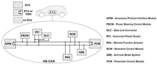
Figure 3.
Schematic view of the in-vehicle high-speed CAN bus that we use for the digital twin.
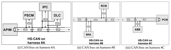
Figure 4.
Wire and stub lengths for the in-vehicle high-speed CAN bus from vehicle harnesses.
The first wiring harness connects three nodes to the CAN bus, i.e., the APIM, PSCM and IPC. It also provides external access to the bus via the DLC connector. The second wiring harness links the RFA and RCM to the bus, while the last one connects the ABS and PCM to the network. The total wire length excluding stubs is of 510 cm, i.e., from the first to the last ECU. The stubs have various lengths starting from 15 cm for the PSCM, 25 cm for the ABS, up to 50 cm for the IPC and even up to 100 cm for the RCM and 120 cm for the RFA. Two nodes, APIM and PCM, include the required CAN bus termination resistors of 120 Ω.
4. System Level Implementation Based on Simulink Models
In this section, we describe the Simulink models, which implement the functionalities of the seven ECUs from our network. Based on these models, we generated the C code, which was flashed on the controllers to obtain the corresponding functionalities.
Design and Validation of Models
In Figure 5, we show an overview of the system model and the signal flow between the ECUs. In what follows, we discuss the Simulink model for each ECU, i.e., PSCM, ABS, PCM, IPC, RCM, APIM and RFA. Additionally, in this figure, we depict the RestBus simulation tool from which the models acquire their inputs (marked with orange), i.e., direction, brake command, buckle status, steering wheel and door-lock button. A Restbus simulation is generally used to provide the inputs required to validate ECU functionalities (https://www.ni.com/ro-ro/innovations/white-papers/12/the-fundamentals-of-restbus-simulation.html, accessed on 26 November 2022). The vehicle speed signal (marked with green) is computed by the ABS ECU and used by other ECUs, e.g., PSCM, PCM.
Figure 5.
Overview of the Simulink model including the seven Electronic Control Units (ECUs).
- 1.
- Power Steering Control Module (PSCM): In Figure 6, we illustrate the implementation of the steering controller, which computes the steering command based on the steering wheel angle from the driver and the vehicle speed. To implement the steering controller, we use the Mapped Steering block from the Simulink library. This block computes the left and right wheel angles based on the steering wheel angle and vehicle speed using interpolation tables. Using the right wheel angle, we then compute the vehicle trajectory, i.e., , , as shown in Equations (1) and (2) and rotation angle, i.e., , as depicted in Equation (3):
 Figure 6. Simulink model for Power Steering Control Module (PSCM) ECU.
 - 2.
- Anti-lock Brake System (ABS): In Figure 7i, we model the estimation of the speed for each wheel based on vehicle speed and brake information (when the brake is pressed, the speed of each wheel is decreased using an integral controller). In Figure 7ii, we depict the calculation of the brake command for the front-left wheel. In Figure 7iii, we depict the calculation of the vehicle speed after braking using a proportional controller, which uses as a limit the preset vehicle speed target when the ABS is not braking on any wheel or zero when the ABS is braking on at least one wheel. The ABS ECU computes the slip for each wheel as shown in Equation (4):
 Figure 7. Simulink model for Anti-lock Brake System (ABS) ECU.In this equation, s is the slip of a wheel, is the speed of the wheel and v is the vehicle speed. The state of the brake command is computed based on the slip of the wheel and vehicle speed, i.e., (input valve is open and output valve is closed, the pressure goes to the wheel), (wheel is locked, input valve is closed to prevent more pressure to the wheel) and (the output valve is open, the pressure is released and the wheel can rotate). The state of the brake commands is used to control the valves, i.e., to open or close the valves. The same functionally is implemented on all vehicle wheels.
 - 3.
- Powertrain Control Module (PCM): The PCM implements very complex functionalities in order to ensure the efficiency and stability of the engine. In our model, we compute the main functionalities of the PCM, i.e., acceleration, torque, gear, engine speed, engine power, air mass flow, fuel flow, exhaust temperature, efficiency and emission performance. In Figure 8, we depict our implementation of the PCM module. Based on vehicle speed, as outlined in Equation (5), we compute the vehicle acceleration as the derivative of the vehicle speed with respect to time:
 Figure 8. Simulink model for Powertrain Control Module (PCM) ECU.As part of the equation terms, is the acceleration, v is the vehicle speed and t represents the time. In order to eliminate the spike of the acceleration value, we apply two low pass filters with a filtering coefficient of 0.1. The gear is computed using a interpolation table, which has as an input the vehicle speed and uses the flat interpolation method to select the corresponding value of the gear. Based on the engine speed and gear, we estimate the engine torque using a 2-D lookup table. Using the gear of the vehicle, we compute the engine speed as presented in Equation (6):In the equation above, is the engine speed, is the shaft vehicle speed, is the axle ratio and is the transmission ratio for each gear. The shaft vehicle speed is computed based on vehicle speed as shown in Equation (7):In this case, v is the vehicle speed and 0.381(m) is the considered wheel radius.To compute other powertrain signals, we used the Mapped SI Engine block from the Simulink library, which implements a spark-ignition engine model based on the torque and engine speed. This model uses several look-up tables to compute the engine air mass flow, normalized engine cylinder air mass, air-fuel ratio (AFR), engine fuel flow, volumetric fuel flow, engine exhaust gas temperature, engine crankshaft absolute angle, engine brake-specific fuel consumption, engine out hydrocarbon emission mass flow, engine out carbon monoxide emission mass flow rate, engine out nitric oxide and nitrogen dioxide emissions mass flow, engine out carbon dioxide emission mass flow, engine out particulate matter emission mass flow, crankshaft power, fuel input power and power loss.
 - 4.
- Instrument Panel Cluster (IPC): The IPC module displays considerable information for the driver that is received from other ECUs or are internally computed. In our work, the IPC module computes the trip distance, average vehicle speed and the buckle alert. In Figure 9i, we show the model for the calculation of the the buckle status (if the car is moving with more than 10 m/s and the seatbelt is not buckled, the buckle alert is shown to the driver). In Figure 9ii, we show the implementation of the trip distance, which is computed as the integral of vehicle speed as outlined in Equation (8):
 Figure 9. Simulink model for Instrument Panel Cluster (IPC) ECU.Due to the fact that the vehicle speed is computed in m/s in our models, in order to have the trip distance in km, we convert it from meter to kilometer and round it to two decimals. In Figure 9iii, we depict the calculation on the average vehicle speed.
 - 5.
- Restraints Control Module (RCM): In Figure 10i, we show the Simulink model for the calculation of the airbag status based on vehicle speed and buckle status (if the car is moving with more than 10 m/s and the seatbelt is buckled, the airbag is active).
 Figure 10. Simulink models for Restraints Control Module (RCM) and Accessory Protocol Interface Module (APIM) ECUs.
 - 6.
- Accessory Protocol Interface Module (APIM): In Figure 10ii, we show the Simulink model for the calculation of the rear camera status based on direction. If the car is moving in reverse, the rear camera is turned on. Otherwise, the rear camera is turned off.
- 7.
- Remote Function Actuator (RFA): In Figure 11, we show the Simulink model for the calculation of door status based on a signal acquired from a button. If the door lock button is continuously pressed and the door is unlocked, after 1 s, the door status is updated to locked. If the door is locked, the status is updated to unlocked after another second.
 Figure 11. Simulink model for Remote Function Actuator (RFA) ECU.
5. Hardware and Software Level Deployment of the Digital Twin
We analyzed open-access CAN databases from opendbc (https://github.com/commaai/opendbc, accessed on 26 November 2022) to guide us in choosing appropriate frames and signals for the models and the CAN tool. By verifying the frame content in several database files, we have extracted relevant signals for the models we use in the digital twin setup. Some of these signals were encoded into 15 bits. We extend them to 16 bits in order to use 2 bytes from the data field for easing data manipulation in software. A detailed description of all signals used and their need is elaborated upon in what follows next.
In order to transmit the input data required by the Simulink models, we have developed a tool in C# that incorporates the XL Driver Library from Vector (https://www.vector.com/int/en/products/products-a-z/libraries-drivers/xl-driver-library/, accessed on 26 November 2022). This library allows a CAN frame transmission on the vehicle bus using the Vector hardware device and parses the frame content for all received frames. Using a configurable micro-second level timer, CAN frames are transmitted periodically from the tool using the USB device from Vector with CAN Interface, i.e., VN5610. Our tool allows the user to initialize the communication with the Vector device, select specific values for the CAN signals from combo-boxes (default values are already set at tool startup), which are transmitted on CAN based on the mapping of real values to CAN raw data bytes. Transmission can be started or stopped at any time. The signals transmitted from the C# tool together with their bit size are shown in the first part of Table 1 and are as follows: vehicle speed target, vehicle direction to specify if the vehicle is driven straight or in reverse, brake status to command the brake, steering wheel angle to compute the vehicle steering and buckle status for airbag control and audible alert for the driver. The tool allows the user to see real-time CAN frames, i.e., labeled as “Received frames”, as well as the relevant signal interpretation, e.g., “Vehicle Speed”, “Gear” or “Trip distance". The user interface for the C#-based tool is depicted in Figure 12.

Table 1.
Summary of signals transmitted by CAN bus nodes.
Figure 12.
User interface for the transmission and visualization of CAN signals.
As models of legitimate ECUs, we employed seven development boards with software applications that transmit model outputs as signals in CAN frames on the real vehicle bus. The boards are Infineon TC275 lite kits with USB support for the PC. They embed an AURIX TC275 microcontroller together with a TLE9251VSJ CAN Transceiver and include a CAN connector interface with a 120 Ω resistor between CANH and CANL. The AURIX TC275 controller has three cores running at 200 MHz, 4MB of Flash memory and 472KB of SRAM. Furthermore, according to information from its datasheet, this microcontroller variant is designed to be used in various automotive safety applications, such as braking control units, airbag control units, powertrain control units and electric power steering control units. One of the AURIX TC275 lite kits used in our experiments is shown in Figure 13i.
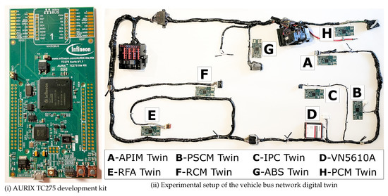
Figure 13.
AURIX node and experimental setup for CarTwin.
For transmission and reception of messages from the CAN bus, we configured P20.8 and P20.7 pin as CAN TX and CAN RX since they are already connected via PCB traces to the existing CAN transceiver on the evaluation kits. We configured P20.6 pin as an output with LOW state to enable the normal operation of the CAN transceiver since this pin is connected to the standby input of the transceiver. In order to preserve the required CAN bus impedance, we kept the 120 Ω resistor only on the boards that are terminal nodes, i.e., the first and the last, and removed the resistors from the other five boards. In this way, the CAN bus is terminated with 2 × 120 Ω resistors between CANH and CANL.
In order to use the CAN network from the vehicle wiring harness, we cut the CAN wires before the original vehicle connectors and soldered 2.54 mm headers on them. The headers were connected to the 2.54 mm male connectors, which were available on each development board as a CAN bus connector. The experimental setup that contains the in-vehicle ECU models and the VN5610A connected to the wiring harness is shown in Figure 13ii.
We now describe the software deployment for creating the digital twin on the automotive-grade controllers. For generating the Simulink models as C code, we used the Simulink Embedded Coder feature from MATLAB (https://www.mathworks.com/help/ecoder/, accessed on 26 November 2022). This feature allows the generation of C and C++ code using specific tool settings that we detail as follows. The settings we configured for each model are: (1) fixed step solver type with discrete states so we could configure the step time according to the task execution time on the embedded device, (2) step size was set to 20 milliseconds since the task cycle time configured in the AURIX software is of 20 ms and (3) device vendor was set to “Infineon” and device type set to “TriCore” so the variable types and endianess are generated as C code according to the hardware target capabilities.
We had to perform one more step in Simulink for each model before we could generate and integrate the code on the embedded hardware target. Where there were any continuous-time blocks, we had to replace them with discrete-time blocks with the same functionality, e.g., continuous integrator blocks with discrete integrator blocks that use the configured step time.
After the model was generated as C code, we integrated it in the embedded project from AURIX studio that we configured for the Infineon AURIX TC275 microcontroller. As model execution steps inside the software project we start with the initialization functions, i.e., in order to initialize the local variables and data structures according to the model settings. Then, we execute the model step function every 20 milliseconds to consume the input data received from CAN bus, i.e., from the tool or from other models. After executing the step function, the outputs from the model are transmitted as CAN bus signals that can be split into multiple CAN frames depending on the content. The ABS twin computes the valve status and slip for each wheel (front left, front right, rear left, rear right) and transmits the calculated vehicle speed on CAN based on the braking status information. The powertrain twin computes the vehicle acceleration, engine torque, etc., and transmits the engine speed and gear position on the bus. The power-steering twin computes and provides the steering offset of the vehicle considering the steering wheel angle value and also sends the X and Y position relative to the vehicle starting point. The restraint control module provides the airbag status, taking into account the buckle status received from the vehicle bus. The instrument panel cluster provides as outputs on the CAN bus the average vehicle speed and trip distance based on the received vehicle speed values and the buckle alert using the buckle status from the CAN tool frame. The remote function actuator modifies and transmits the door lock status, taking into account if the door lock button is pressed using a debounce time of 1 s. The accessory protocol interface module will activate the rear-view camera if the vehicle is driven backwards and will constantly provide the rear-camera video status on the vehicle bus. CAN output signal information that includes bit size transmitted by each ECU model from the CarTwin setup is shown in the second part of Table 1, while the first part of the table details the signals transmitted from the C# tool.
6. Experimental Evaluation of the Digital Twin
In the first part of this section, we provide details related to the Matlab/Simulink model integration in the CarTwin experimental setup and compare data extracted from a real-world vehicle trace with the output from our CarTwin models. Then, we discuss possible applications and future improvements for CarTwin. Finally, we compare CarTwin with related approaches for digital twins in the automotive domain.
First of all, in order to verify the correctness of the ECU model integration on the CAN bus, we provided the same input signals to each of the models in Matlab/Simulink and from the CarTwin setup using the C# tool, logged the outputs from the experiments and verified that the output value arrays are the same in Matlab/Simulink and on the CAN bus. For evaluation purposes, the signals of interest that we analyzed from the vehicle trace and the CarTwin model are: (a) vehicle speed, (b) engine speed and (c) trip distance.
6.1. Results
In order to correlate the model outputs with the real-world vehicle data, we estimated the brake signal based on vehicle speed variations from the real-world vehicle trace and used it as an input in the CarTwin model. The vehicle direction input was always transmitted as straight, i.e., vehicle is always moving forward. The target vehicle speed, that is also the initial vehicle speed in the model, is of 140 km/h. While the brake is not active, the vehicle speed will increase up to the target vehicle speed. Next, we show one trial of collected vehicle data compared to the CarTwin model output. The model output signals are shown in Figure 14i,iii,v, while the real-world vehicle signals are shown in Figure 14ii,iv,vi.
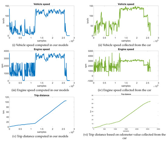
Figure 14.
Signals computed by CarTwin models (left) and signals collected from a car (right).
The real-world vehicle trace contains a normal drive scenario on local roads and on the highway with a total duration of 44 min. There are two frames in the trace that we used to extract the vehicle speed, engine speed and odometer value. Vehicle speed and engine speed are transmitted every 10 ms, while the odometer is sent every 1 s. In the CarTwin model, we directly computed the trip distance based on vehicle speed, while in the vehicle trace, we used the odometer value. In order to correlate the model output with the vehicle trace, we subtracted in the latter the initial odometer value from the trace. From the vehicle trace, we extracted more than ∼250 k samples for the vehicle speed and engine speed, as shown in Figure 14ii,iv, and more than ∼2.5 k samples for the vehicle trip distance based on the odometer value, as shown in Figure 14vi. Considering the vehicle speed and engine speed changes between local road and highway driving locations and conditions, we emphasize the CarTwin behavior under similar conditions in what follows. In the collected trace, the vehicle speed varies between 0 km/h and 60 km/h during the first ∼100 k samples and is approximately 130 km/h for the next ∼150 k samples, while the vehicle is on the highway, as shown in Figure 14ii. The engine speed, depicted in Figure 14iv, varies with the vehicle speed between 1000 rpm and 4500 rpm at lower vehicle speeds and stays close to 3000 rpm while the vehicle speed increased, in the second part of the trace. In Figure 14vi, it can be seen that the trip distance value has a slow increase in the first part of the trace, and after that, it grows linearly due to the fact that the vehicle speed is quite stable around 130 km/h. To compare CarTwin outputs with the vehicle trace signals in a more concise way, we split the entire trace from Figure 14 in two parts based on the driving location. In the first part, as illustrated in Figure 15, the vehicle is driven on local roads, and in the second part, as shown in Figure 16, it is driven on a highway.
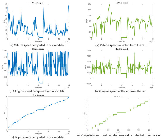
Figure 15.
Signals computed by CarTwin models (left) and signals collected from a car (right) on local roads.
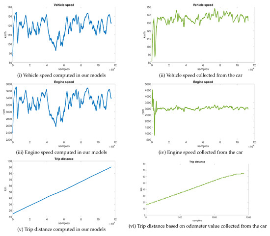
Figure 16.
Signals computed by CarTwin models (left) and signals collected from a car (right) on highway.
Local roads. In Figure 15, we show the signals while the vehicle is driven in the city and on local roads. The plots from the left side are the outputs from our simulation, i.e., Figure 15i,iii,v, while the plots from the right side are the signals collected from the real car, i.e., Figure 15ii,iv,vi. For the vehicle speed signal, the model output varies between 0 km/h and 85 km/h, while the vehicle speed signal collected from the vehicle varies between 0 km/h to 80 km/h (with the exception of one spike to 120 km/h during a car overtake in the real scenario). Engine speed varies between 800 rpm and 2500 rpm in the model output, while in the vehicle trace, the signal value is of 900 rpm to 2500 rpm (except for a few spikes at 4500 rpm). We have a different number of samples for the trip distance (between our simulation and the signal collected from the car) because our model runs at 20 ms, while the car CAN bus message that contains the odometer is transmitted every 1 s. However, the trip distance signal has a similar variation over time.
Highway. In Figure 16, we show the signals while the vehicle is driven on a highway. Again, the plots from the left side are the outputs from our simulation, i.e., Figure 16i,iii,v, while the plots from the right side are the signals collected from the real car, i.e., Figure 16ii,iv,vi. For the vehicle speed signal, the model output varies between 90 km/h and 135 km/h, while the vehicle speed signal collected from the vehicle varies between 125 km/h to 148 km/h (with the exception of a few spikes to 80 km/h at the beginning of the plot). Engine speed varies between 2600 rpm and 3700 rpm in the model output, while in the vehicle trace, the signal value is more stable between 2600 rpm and 3400 rpm (except for a few spikes at the beginning of the plot between 1000 rpm and 4600 rpm). The trip distance signal from the model and the trip distance signal from the car have a similar variation in time.
Statistical comparison. As an additional metric for the accuracy of the model outputs, we compute the mean values for the differences between the output signals of the model and those from the vehicle trace and the correlation coefficient between these signals. To provide a comprehensive evaluation for the computed mean difference, we show several plots with the distribution of vehicle speed and engine speed signals from the model output, vehicle trace and the difference between them. The distribution of the vehicle speed from the model is shown in Figure 17i, with more than 20% of values in each of the following ranges: 0–20 km/h, 100–120 km/h and 120–140 km/h. The distribution of the engine speed from the model is shown in Figure 17ii, with 30% of the values in the 3240–3780 rpm range and more than 20% of the values in the 540–1080 rpm and 2700–3240 rpm ranges. The vehicle speed from the vehicle trace has more than 30% of the values in the 132–154 km/h range while driving on the highway and around 25% of values in the 44–66 km/h range while driving on local roads, as shown in Figure 17iii. The engine speed was in the 2800–3500 rpm range for more than 40% of occurrences in the vehicle trace and around 25% within the 1400–2100 rpm range, as illustrated in Figure 17iv. The distribution for the vehicle speed difference is shown in Figure 17v, with 46% of values in the 0–20 km/h range and 80% of values in the 0–40 km/h range, while the distribution for the engine speed difference is shown in Figure 17vi, with 60% of values in the 0–560 rpm range and 83% of values in the 0–1120 rpm range. Numerical data, which contains the bin width and the bin percentages for each of the seven bins from the distributions, is presented in Table 2.
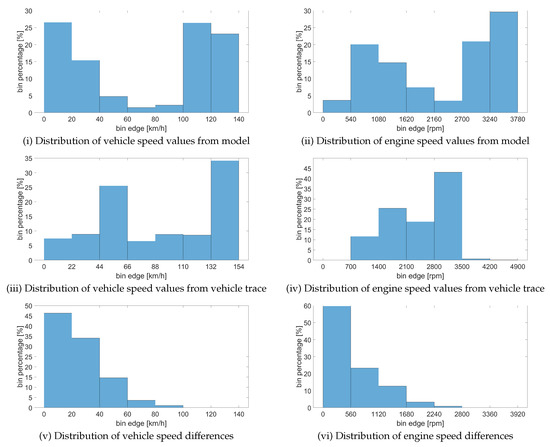
Figure 17.
Distribution of values from model output, vehicle trace and differences between them for vehicle speed (left) and engine speed (right).
Table 2.
Statistical data for distribution of the model output, real vehicle signal and their differences.
The distributions, mean difference and correlation coefficient values were computed for the entire trace, which includes both driving on the local road and the highway, and are shown in Table 3. Since the digital twin model is designed by us in MATLAB/Simulink, while the real-world vehicle is an actual physical system that is influenced by the environment, differences between the results are expected (both the vehicle and the environment are nearly impossible to model with absolute accuracy). The mean of the recorded differences is about 25 km/h for the vehicle speed and 610 rpm for the engine speed. We note that the range of the signals is computed according to the collected dataset, and the only common input that links the synthetic model with the physical is the signal applied to the brakes. The correlation coefficients between the synthetic data and the real-world data are 0.85 and 0.71, respectively (for the vehicle and engine speed), which shows a good to strong relation between the synthetic and the real-world result.
Table 3.
Statistical comparison of the synthetic model outputs with the real vehicle signals.
6.2. Possible Applications
A possible application for the experimental model is in the evaluation of cyberattacks on in-vehicle networks. Indeed, many related works on intrusion detection for in-vehicle buses use real-world traces collected inside the vehicle that are augmented with attacks in an off-line manner, e.g., [51,52,53]. One of the most common attacks in such works are fuzzing attacks in which frames containing random data are sent on the bus [54,55,56]. Clearly, exposing the actual car to such an attack may cause safety concerns since random packets may cause unexpected behavior for the car, a reason for which the off-line attack procedure is a good choice. However, this off-line attack procedure overlooks the impact of one parameter on another. As we show in Figure 18i,iii, when the vehicle speed and engine speed are subject to an off-line attack augmentation, the attack values will show as spikes on the original signals. These spikes on the vehicle speed and engine speed are, however, poorly correlated, which is not necessarily the case in a real vehicle. Obviously, in reality, there is good correlation between these two signals, and thus, the off-line attacks may be quite artificial. This is visible in Table 4, where the correlation between the two attacked signals is 0, which is expected as the attack values are random, while in the real-world data as well as in the CarTwin experimental model, the correlation between legitimate frames for the same signals is around 0.9. The lack of correlation between these two signals (vehicle speed and engine speed) will make such attacks easier to detect but also not very realistic for the real-world behavior of the car. In Figure 18ii,iv, we show how an attack on the vehicle speed will influence engine speed when the CarTwin model is employed. The correlation is significantly better for the attacks on the CarTwin model as can be seen in Table 4. Even in case of the attack frames on vehicle speed and their impact on engine speed, the correlation coefficient is still 0.49 (note that in the off-line generated trace, the correlation is 0). There is a decreased correlation with an increase in the attack probability, which is expected (as the attack becomes more frequent, the correlation lowers since the attack represents an anomaly). While it is out of scope for us to delve further into security-related details, this suggests CarTwin to be useful in gaining insights into cyberattacks.
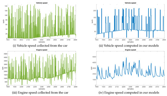
Figure 18.
Vehicle speed and engine speed under a fuzzing attack with 25% probability in an off-line augmented trace (left) and the same signals within the CarTwin models (right).
Table 4.
Attack correlation augmented trace vs. CarTwin.
Another possible area of investigation for the model is safety and fault tolerance. Our model does contain safety-relevant signals, such as brake, buckle and airbag status signals, etc. Fault tolerance is indeed highly recommended or even mandatory in case of safety critical signals. A well-known and employed solution to assure fault-tolerance is redundancy, either by using different sources for a signal or deriving it by distinct computations. For a case in which these signals are faulty, redundancy is a means to correct such faults. For example, vehicle speed is reported both by the ABS and PCM controllers, both of which are present in our model, etc. Such consistency checks can also be performed based on the data from the model.
6.3. Comparison to Related Works
The design of digital twins for cars is only a recently emerged topic, and there is only a very limited number of related works that can be immediately compared with the developments from our work. As already stated in the introduction, an implementation of digital twins for vehicle dynamics using the steering system, braking system and powertrain is analyzed by authors in [9]. Our work improves on this with the use of a real-world vehicle bus topology, besides the definition and implementation of control system models on the ECUs. A research team from Toyota has designed PASTA (Portable Automotive Security Testbed with Adaptability) [57], an adaptable vehicle cybersecurity testbed as an evaluation environment for automotive attacks. Their testbed integrates development boards with models for various ECUs functionalities from real-world vehicles, which communicate on two separate CAN networks connected through a Gateway unit. One recent work, RAMN (Resistant Automotive Miniature Network) [58], designs a small and inexpensive automotive testbed that includes implementation of models for the gateway, powertrain, chassis and body ECUs connected to a single CAN bus. A comparison of our work with research papers that address vehicle-level functions using digital twins is shown in Table 5.
Table 5.
Comparison of research papers addressing Digital Twins for ECUs or automotive testbeds.
7. Conclusions
Vehicle functionalities require rigorous models and realistic experimental frameworks for comprehensive design and testing. Digital twins can greatly serve this purpose. Still, creating a digital twin for a car is challenging, as it requires not only the models for each functionality, but also the networking layer. In this work, we constructed a CAN bus experimental setup for creating the digital twin of a car using a real-world vehicle wiring harness. On the experimental setup, we integrated ECU functionalities on automotive-grade microcontrollers using code generated from the Simulink models that we designed, e.g., related to transmission or braking. We also defined the scenario parameters and analyzed the run-time outputs of all models that interact on the CAN Bus. All models receive vehicle data inputs from a software interface, connected to a CAN interface, that reproduce the signals required by the CarTwin models. In the end, we compared several output signals of the CarTwin model with signals collected from a real-world vehicle while driving it on local roads and on the highway. The analysis shows that there is good correlation between the output from our models and the data extracted from the real car that we used as a reference.
Author Contributions
Conceptualization, B.G.; methodology, B.G.; implementation, L.P. and A.B.; validation, L.P. and A.B.; investigation, L.P. and A.B.; resources, L.P.; writing—original draft preparation, L.P., A.B. and B.G.; writing—review and editing, L.P., A.B. and B.G.; supervision, B.G.; project administration, B.G. All authors have read and agreed to the published version of the manuscript.
Funding
This paper was financially supported by the project “Network of excellence in applied research and innovation for doctoral and postdoctoral programs/InoHubDoc”; project co-funded by the European Social Fund financing agreement No. POCU/993/6/13/153437.
Institutional Review Board Statement
Not applicable.
Informed Consent Statement
Not applicable.
Data Availability Statement
Not applicable.
Conflicts of Interest
The authors declare no conflict of interest.
References
- Kuhnert, F.; Stürmer, C.; Koster, A. Five Trends Transforming the Automotive Industry; PricewaterhouseCoopers GmbH Wirtschaftsprüfungsgesellschaft: Berlin, Germany, 2018; Volume 1, pp. 1–48. [Google Scholar]
- Fathy, H.K.; Filipi, Z.S.; Hagena, J.; Stein, J.L. Review of hardware-in-the-loop simulation and its prospects in the automotive area. In Proceedings of the Modeling and Simulation for Military Applications, Orlando, FL, USA, 22 May 2006; Volume 6228, pp. 117–136. [Google Scholar] [CrossRef]
- Belhocine, A.; Bouchetara, M. Thermomechanical modelling of dry contacts in automotive disc brake. Int. J. Therm. Sci. 2012, 60, 161–170. [Google Scholar] [CrossRef]
- Rassõlkin, A.; Vaimann, T.; Kallaste, A.; Kuts, V. Digital twin for propulsion drive of autonomous electric vehicle. In Proceedings of the 2019 IEEE 60th International Scientific Conference on Power and Electrical Engineering of Riga Technical University (RTUCON), Riga, Latvia, 7–9 October 2019; pp. 1–4. [Google Scholar] [CrossRef]
- Grieves, M. Digital twin: Manufacturing excellence through virtual factory replication. White Paper 2014, 1, 1–7. [Google Scholar]
- INCOSE. Definition for Digital Twin; INCOSE: San Diego, CA, USA, 2022. [Google Scholar]
- Madni, A.M.; Madni, C.C.; Lucero, S.D. Leveraging Digital Twin Technology in Model-Based Systems Engineering. Systems 2019, 7, 7. [Google Scholar] [CrossRef]
- Cimino, C.; Negri, E.; Fumagalli, L. Review of digital twin applications in manufacturing. Comput. Ind. 2019, 113, 103130. [Google Scholar] [CrossRef]
- Shetty, S.S. Development of a Digital Twin of a Toyota Prius Mk4. Master’s Thesis, Eindhoven University of Technology, Eindhoven, The Netherlands, 2022. [Google Scholar]
- Koscher, K.; Czeskis, A.; Roesner, F.; Patel, S.; Kohno, T.; Checkoway, S.; McCoy, D.; Kantor, B.; Anderson, D.; Shacham, H.; et al. Experimental Security Analysis of a Modern Automobile. In Proceedings of the 2010 IEEE Symposium on Security and Privacy, Oakland, CA, USA, 16–19 May 2010; pp. 447–462. [Google Scholar] [CrossRef]
- Checkoway, S.; McCoy, D.; Kantor, B.; Anderson, D.; Shacham, H.; Savage, S.; Koscher, K.; Czeskis, A.; Roesner, F.; Kohno, T. Comprehensive Experimental Analyses of Automotive Attack Surfaces. In Proceedings of the 20th USENIX Conference on Security, San Diego, CA, USA, 10–12 August 2011; p. 6. [Google Scholar]
- Nie, S.; Liu, L.; Du, Y. Free-Fall: Hacking Tesla from Wireless to CAN Bus. Briefing Black Hat USA 2017, 25, 1–16. [Google Scholar]
- ISO11898-1; Road Vehicles—Controller Area Network (CAN)—Part 1: Data Link Layer and Physical Signalling. International Organization for Standardization: Geneva, Switzerland, 2015.
- ISO11898-2; Road Vehicles—Controller Area Network (CAN)—Part 2: High-Speed Medium Access Unit. International Organization for Standardization: Geneva, Switzerland, 2016.
- Zuberi, K.M.; Shin, K.G. Non-Preemptive Scheduling of Messages on Controller Area Network for Real-Time Control Applications. In Proceedings of the Real-Time Technology and Applications Symposium, Chicago, IL, USA, 15–17 May 1995; pp. 240–249. [Google Scholar] [CrossRef]
- Livani, M.A.; Kaiser, J.; Jia, W. Scheduling Hard and Soft Real-Time Communication in a Controller Area Network. Control Eng. Prac. 1999, 7, 1515–1523. [Google Scholar] [CrossRef]
- Tindell, K.; Burns, A.; Wellings, A. Calculating Controller Area Network (CAN) Message Response Times. IFAC Proc. Vol. 1994, 27, 35–40. [Google Scholar] [CrossRef]
- Leen, G.; Heffernan, D. TTCAN: A new time-triggered controller area network. Microprocess. Microsyst. 2002, 26, 77–94. [Google Scholar] [CrossRef]
- Farsi, M.; Ratcliff, K.; Barbosa, M. An introduction to CANopen. Comput. Control Eng. J. 1999, 10, 161–168. [Google Scholar] [CrossRef]
- Proenza, J.; Miro-Julia, J. MajorCAN: A Modification to the Controller Area Network Protocol to Achieve Atomic Broadcast. In Proceedings of the ICDCS Workshop on Group Communications and Computations, Taipei, Taiwan, 10 April 2000; pp. C72–C79. [Google Scholar]
- Ziermann, T.; Wildermann, S.; Teich, J. CAN+: A new backward-compatible Controller Area Network (CAN) protocol with up to 16× higher data rates. In Proceedings of the 2009 Design, Automation & Test in Europe Conference & Exhibition, Nice, France, 20–24 April 2009; pp. 1088–1093. [Google Scholar] [CrossRef]
- Uhlemann, T.H.J.; Lehmann, C.; Steinhilper, R. The digital twin: Realizing the Cyber-Physical Production System for Industry 4.0. Procedia CIRP 2017, 61, 335–340. [Google Scholar] [CrossRef]
- Aheleroff, S.; Xu, X.; Zhong, R.Y.; Lu, Y. Digital Twin as a Service (DTaaS) in Industry 4.0: An Architecture Reference Model. Adv. Eng. Inform. 2021, 47, 101225. [Google Scholar] [CrossRef]
- Hänel, A.; Schnellhardt, T.; Wenkler, E.; Nestler, A.; Brosius, A.; Corinth, C.; Fay, A.; Ihlenfeldt, S. The development of a digital twin for machining processes for the application in aerospace industry. Procedia CIRP 2020, 93, 1399–1404. [Google Scholar] [CrossRef]
- Wanasinghe, T.R.; Wroblewski, L.; Petersen, B.K.; Gosine, R.G.; James, L.A.; De Silva, O.; Mann, G.K.; Warrian, P.J. Digital twin for the Oil and Gas Industry: Overview, Research Trends, Opportunities, and Challenges. IEEE Access 2020, 8, 104175–104197. [Google Scholar] [CrossRef]
- Rodrigues, T.K.; Liu, J.; Kato, N. Application of Cybertwin for Offloading in Mobile Multiaccess Edge Computing for 6G Networks. IEEE Internet Things J. 2021, 8, 16231–16242. [Google Scholar] [CrossRef]
- Liu, Y.; Zhang, L.; Yang, Y.; Zhou, L.; Ren, L.; Wang, F.; Liu, R.; Pang, Z.; Deen, M.J. A Novel Cloud-Based Framework for the Elderly Healthcare Services Using Digital Twin. IEEE Access 2019, 7, 49088–49101. [Google Scholar] [CrossRef]
- Magargle, R.; Johnson, L.; Mandloi, P.; Davoudabadi, P.; Kesarkar, O.; Krishnaswamy, S.; Batteh, J.; Pitchaikani, A. A Simulation-Based Digital Twin for Model-Driven Health Monitoring and Predictive Maintenance of an Automotive Braking System. In Proceedings of the 12th International Modelica Conference, Prague, Czech Republic, 15–17 May 2017; pp. 35–46. [Google Scholar] [CrossRef]
- Merkle, L.; Segura, A.S.; Grummel, J.T.; Lienkamp, M. Architecture of a Digital Twin for Enabling Digital Services for Battery Systems. In Proceedings of the 2019 IEEE International Conference on Industrial Cyber Physical Systems (ICPS), Taipei, Taiwan, 6–9 May 2019; pp. 155–160. [Google Scholar] [CrossRef]
- Tharma, R.; Winter, R.; Eigner, M. An Approach for the Implementation of the Digital Twin in the Automotive Wiring Harness Field. In Proceedings of the DS 92, DESIGN 2018 15th International Design Conference, Dubrovnik, Croatia, 21–24 May 2018; pp. 3023–3032. [Google Scholar] [CrossRef]
- Yu, B.; Chen, C.; Tang, J.; Liu, S.; Gaudiot, J.L. Autonomous Vehicles Digital Twin: A Practical Paradigm for Autonomous Driving System Development. Computer 2022, 55, 26–34. [Google Scholar] [CrossRef]
- Conti, M.; Donadel, D.; Turrin, F. A Survey on Industrial Control System Testbeds and Datasets for Security Research. IEEE Commun. Surv. Tutor. 2021, 23, 2248–2294. [Google Scholar] [CrossRef]
- Damjanovic-Behrendt, V. A Digital Twin-based Privacy Enhancement Mechanism for the Automotive Industry. In Proceedings of the 2018 International Conference on Intelligent Systems (IS), Funchal, Portugal, 25–27 September 2018; pp. 272–279. [Google Scholar] [CrossRef]
- Pokhrel, A.; Katta, V.; Colomo-Palacios, R. Digital Twin for Cybersecurity Incident Prediction: A Multivocal Literature Review. In Proceedings of the IEEE/ACM 42nd International Conference on Software Engineering Workshops, Seoul, Republic of Korea, 27 June–19 July 2020; pp. 671–678. [Google Scholar] [CrossRef]
- Sellitto, G.P.; Masi, M.; Pavleska, T.; Aranha, H. A Cyber Security Digital Twin for Critical Infrastructure Protection: The Intelligent Transport System Use Case. In Proceedings of the IFIP Working Conference on The Practice of Enterprise Modeling, Riga, Latvia, 24–26 November 2021; pp. 230–244. [Google Scholar] [CrossRef]
- R20-11; Specification of Secure Onboard Communication. AUTOSAR: San Diego, CA, USA, 2020.
- Kurt, B.; Gören, S. Development of a Mobile News Reader Application Compatible with In-Vehicle Infotainment. In Proceedings of the International Conference on Mobile Web and Intelligent Information Systems, Barcelona, Spain, 6–8 August 2018; pp. 18–29. [Google Scholar] [CrossRef]
- Lee, D.; Kim, K.S.; Kim, S. Controller Design of an Electric Power Steering System. IEEE Trans. Control Syst. Technol. 2017, 26, 748–755. [Google Scholar] [CrossRef]
- Gurban, E.H.; Groza, B.; Murvay, P.S. Risk Assessment and Security Countermeasures for Vehicular Instrument Clusters. In Proceedings of the 2018 48th Annual IEEE/IFIP International Conference on Dependable Systems and Networks Workshops (DSN-W), Luxembourg, 25–28 June 2018; pp. 223–230. [Google Scholar] [CrossRef]
- Groza, B.; Gurban, H.E.; Murvay, P.S. Designing Security for In-vehicle Networks: A Body Control Module (BCM) Centered Viewpoint. In Proceedings of the Dependable Systems and Networks Workshop, Toulouse, France, 28 June–1 July 2016; pp. 176–183. [Google Scholar] [CrossRef]
- Garcia, F.; Oswald, D.; Kasper, T.; Pavlides, P. Lock It and Still Lose It—On the (In)Security of Automotive Remote Keyless Entry Systems. In Proceedings of the 25th USENIX Security Symposium, USENIX Association, Austin, TX, USA, 10–12 August 2016; pp. 929–944. [Google Scholar]
- Oswald, D.F. Wireless Attacks on Automotive Remote Keyless Entry Systems. In Proceedings of the 6th International Workshop on Trustworthy Embedded Devices, Vienna, Austria, 28 October 2016; pp. 43–44. [Google Scholar] [CrossRef]
- Ibrahim, O.A.; Hussain, A.M.; Oligeri, G.; Di Pietro, R. Key is in the Air: Hacking Remote Keyless Entry Systems. In Security and Safety Interplay of Intelligent Software Systems; Springer: Berlin, Germany, 2018; pp. 125–132. [Google Scholar] [CrossRef]
- Wouters, L.; Marin, E.; Ashur, T.; Gierlichs, B.; Preneel, B. Fast, Furious and Insecure: Passive Keyless Entry and Start Systems in Modern Supercars. IACR Trans. Cryptogr. Hardw. Embed. Syst. 2019, 2019, 66–85. [Google Scholar] [CrossRef]
- Dürrwang, J.; Braun, J.; Rumez, M.; Kriesten, R. Security Evaluation of an Airbag-ECU by Reusing Threat Modeling Artefacts. In Proceedings of the 2017 International Conference on Computational Science and Computational Intelligence (CSCI), Las Vegas, NV, USA, 14–16 December 2017; pp. 37–43. [Google Scholar] [CrossRef]
- Mun, H.; Han, K.; Lee, D.H. Ensuring Safety and Security in CAN-Based Automotive Embedded Systems: A Combination of Design Optimization and Secure Communication. IEEE Trans. Veh. Technol. 2020, 69, 7078–7091. [Google Scholar] [CrossRef]
- Ishak, M.K.; Khan, F.K. Unique Message Authentication Security Approach based Controller Area Network (CAN) for Anti-lock Braking System (ABS) in Vehicle Network. Procedia Comput. Sci. 2019, 160, 93–100. [Google Scholar] [CrossRef]
- Guo, L.; Ye, J.; Du, L. Cyber–Physical Security of Energy-Efficient Powertrain System in Hybrid Electric Vehicles Against Sophisticated Cyberattacks. IEEE Trans. Transp. Electrif. 2020, 7, 636–648. [Google Scholar] [CrossRef]
- Ye, J.; Guo, L.; Yang, B.; Li, F.; Du, L.; Guan, L.; Song, W. Cyber–Physical Security of Powertrain Systems in Modern Electric Vehicles: Vulnerabilities, Challenges, and Future Visions. IEEE J. Emerg. Sel. Top. Power Electron. 2020, 9, 4639–4657. [Google Scholar] [CrossRef]
- Hoff, U.; Scott, D. Challenges for wiring harness development. CAN Newsletter Magazine, March 2020; 14–19. [Google Scholar]
- Zhou, A.; Li, Z.; Shen, Y. Anomaly Detection of CAN Bus Messages Using a Deep Neural Network for Autonomous Vehicles. Appl. Sci. 2019, 9, 3174. [Google Scholar] [CrossRef]
- Hossain, M.D.; Inoue, H.; Ochiai, H.; Fall, D.; Kadobayashi, Y. LSTM-Based Intrusion Detection System for In-Vehicle Can Bus Communications. IEEE Access 2020, 8, 185489–185502. [Google Scholar] [CrossRef]
- Andreica, T.; Curiac, C.D.; Jichici, C.; Groza, B. Android Head Units vs. In-Vehicle ECUs: Performance Assessment for Deploying In-Vehicle Intrusion Detection Systems for the CAN Bus. IEEE Access 2022, 10, 95161–95178. [Google Scholar] [CrossRef]
- Kim, H.; Jeong, Y.; Choi, W.; Lee, D.H.; Jo, H.J. Efficient ECU Analysis Technology Through Structure-Aware CAN Fuzzing. IEEE Access 2022, 10, 23259–23271. [Google Scholar] [CrossRef]
- Aldhyani, T.H.; Alkahtani, H. Attacks to Automatous Vehicles: A Deep Learning Algorithm for Cybersecurity. Sensors 2022, 22, 360. [Google Scholar] [CrossRef]
- Islam, R.; Devnath, M.K.; Samad, M.D.; Al Kadry, S.M.J. GGNB: Graph-based Gaussian naive Bayes intrusion detection system for CAN bus. Veh. Commun. 2022, 33, 100442. [Google Scholar] [CrossRef]
- Toyama, T.; Yoshida, T.; Oguma, H.; Matsumoto, T. PASTA: Portable Automotive Security Testbed with Adaptability; Blackhat Europe: London, UK, 2018. [Google Scholar]
- Gay, C.; Toyama, T.; Oguma, H. Resistant Automotive Miniature Network. In Proceedings of the Chaos Computer Congress, Leipzig, Germany, 27–30 December 2020. [Google Scholar]
Disclaimer/Publisher’s Note: The statements, opinions and data contained in all publications are solely those of the individual author(s) and contributor(s) and not of MDPI and/or the editor(s). MDPI and/or the editor(s) disclaim responsibility for any injury to people or property resulting from any ideas, methods, instructions or products referred to in the content. |
© 2022 by the authors. Licensee MDPI, Basel, Switzerland. This article is an open access article distributed under the terms and conditions of the Creative Commons Attribution (CC BY) license (https://creativecommons.org/licenses/by/4.0/).