Abstract
We conducted research into the visible light detection of conical space targets and proposed a method to determine the caliber of a space-based detection system. We constructed a three-dimensional conical space target radiation transfer model and analyzed the effect of the phase angle between the solar incident direction, the detector’s bore sight direction, and the conical target inclination on the radiation intensity of the space target received by the detector. Finally, we obtained the threshold caliber which can meet the detection requirements of the system with the system signal-to-noise ratio as the evaluation standard, and we took the SBV sensor as an example to verify that the caliber determination method in this paper is effective.
1. Introduction
With the acceleration of human space exploration, the number of spacecraft in orbit, mainly represented by artificial satellites, has increased rapidly. Because spacecraft recovery technology is expensive and difficult to deploy, when an on-orbit spacecraft fails and is scrapped, it will rarely be recovered, and will instead be left to drift around in orbit. Collision with these failed spacecraft will cause the running spacecraft to malfunction or even disintegrate, posing a serious threat to the safe operation of orbiting spacecraft [1,2]. The first satellite collision event in human history occurred over Siberia on 11 February 2009, when an Iridium satellite launched by the United States in 1997 collided with a Cosmos2251 satellite launched by Russia in 1993, highlighting the importance of deploying space target monitoring systems [3,4]. As the space environment grows increasingly complicated, countries represented by the United States are putting in place a strategic layout of space-based space target surveillance systems to improve their ability to govern space resources [5].
The Midcourse Space Experiment (MSX) satellite was launched by the United States in 1996. The MSX satellite is equipped with a 150 mm caliber space-based visible (SBV) sensor, which is used to follow communication satellites in geostationary orbit as well as certain other high-orbit spacecraft [6]. The Block 10 Pathfinder satellite, the first satellite of the space-based space surveillance (SBSS) system, was successfully launched and operated by the United States in 2010, marking the official entry of space target surveillance into the space-based era [7]. The SBSS system is expected to boost U.S. space target monitoring capabilities by 50%, covering a wide range of orbital and ballistic targets in medium, high, and low orbits, and detecting target characteristics. In addition, in 2014, the U.S. and Canada jointly launched the “Sapphire” satellite, which has a photoelectric sensor for tracking and monitoring high-orbit space targets, as well as providing space situational awareness capabilities [8,9]. The monitoring of space-based space targets will become common in the future, thanks to the faster deployment of the high-throughput big satellite constellation. The high-speed interconnected satellite constellations may perform regionally coordinated observations as well as worldwide ubiquitous perception, constituting a “skynet” for future space target surveillance.
The system caliber is one of the most critical elements that influences the resolution of a space target monitoring system and, therefore, indirectly determines target detection accuracy. Visible detection is a popular method of space detection because of its high detection accuracy, intuitive nature, and low elevation angles that are less impacted by ground clutter [10,11]. Visible detection provides distinct benefits for space objects that do not create heat on their own. As a result, the caliber determination technique of the space-based visible space target detection system is investigated in this study [12,13,14]. Because the space-based visible space target detection system detects the target by receiving the radiation energy reflected by the space target, the reflected radiation models established by space targets of various shapes differ, in other words, the shape of the target will affect the reflected radiation energy and, in turn, the radiation intensity received by the detector.
Because satellites are the most observable space targets, this article focuses on satellites as the detection object. The satellite’s main body has a variety of forms, such as spherical, conical, cylindrical, polyhedron-based, prism-like, and dumbbell-like shapes [15,16,17]. The most popular artificial satellites are spheres and cones, and the spherical target’s reflected radiation model is a subset of the conical target model [13]. Therefore, this paper studied the space-based visible light detection of conical space targets, and presented a method for determining the caliber of the space-based visible light detection system. Firstly, we established a three-dimensional conical space target radiation transfer model. Secondly, the effects of the phase angle between the solar incident direction, the bore sight direction of the detector, and the conical target inclination on the radiation intensity of the space target received by the detector were analyzed. Finally, we used the system signal-to-noise ratio as the evaluation standard to obtain a threshold caliber that can meet the system detection requirements, and took the SBV sensor as an example to verify that the caliber determination method in this paper is effective. Therefore, the research in this paper has a certain generalization effect and can be applied to the conventional visible light detection system.
2. Radiation Sources of Space Target
Solar radiation, Earth radiation, background star radiation, and the target’s own radiation are the principal sources of radiation reflected by space targets. The sun, the Earth, and the background stars, for example, can be considered black bodies with temperatures of 5900 K, 300 K, and 3.5 K, respectively. The satellites in sun-synchronous orbit have an average temperature of 314 K in the sunlight zone and 198 K in the shadow zone [18]. Simulations may be used to obtain the radiation output of the sun, Earth, background stars, and satellites at various wavelengths, according to Planck’s law (see Figure 1).
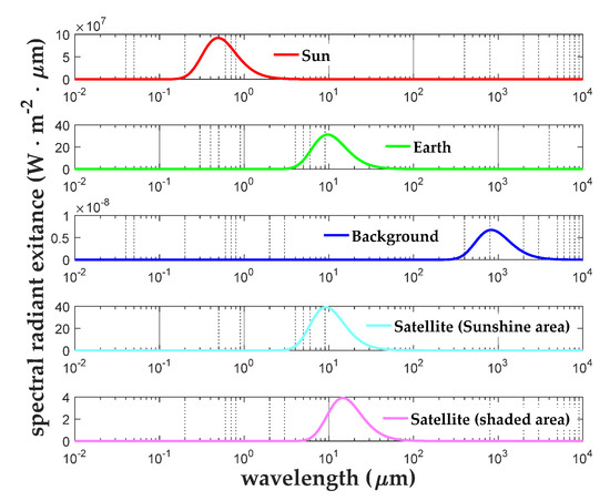
Figure 1.
Radiation emission of various radiation sources of space targets.
Figure 1 shows that the radiation source reflected by the space target in the visible light wave band from 0.3 microns to 0.9 microns is mostly solar radiation. According to Lambert’s law, the sun is equal to a blackbody with temperatures of 5900 K, and the irradiance on the space target from the sun is estimated using Planck’s law and expressed as .
where the visible working wavelength range is from to , and are both simplified constant values, is the solar temperature with value of 5900 K, is the solar radius, and is the Earth–Sun Distance. The intensity of the solar radiation reflected by the space target can be expressed as follows:
where is the space target surface reflectivity which can usually be set to 0.2, is the effective incident cross-sectional area of the space target, is the angle between the incident direction of the solar radiation flux and the normal vector of the space target surface element, and is the angle between the normal vector of the space target surface element and the direction of the radiation flux reflected by the space target received by the detector. Obviously, ,, and directly determine the radiation intensity of the space target received by the detector. The radiation intensity model analysis for space targets generally adopts a two-dimensional model [14,19]. In the visible light band, the three-dimensional radiation transfer model of conical space targets is rarely studied [17]. Next, the analysis will be done for the radiative transfer model of the conical space target.
3. Radiation Model of Conical Space Target
As shown in Figure 2, the radiative transfer model of the conical space target is established. The Z-axis is the direction of the cone axis pointing to the vertex, the projection of the reflected radiation vector on the coordinate plane is the X-axis, and the Y-axis forms the right-hand rule with the X-axis and the Z-axis [17]. is the radius of the bottom of the cone, is the conical target inclination which ranges from to , is the solar incident radiation vector received by the space target, is the radiation vector reflected by the space target received by the detector, is the normal vector of the space target surface bin, is the effective incident cross-sectional area of the space target, is the incident angle between and Z-axis, and its value range is , is the observation angle between and Z-axis, and its value range is , is the angle between and , is the angle between and , is the phase angle between the incident direction of sunlight and the direction of the optical axis of the detector, hereinafter referred to as the phase angle, while is the spatial azimuth of conical target surfel ranging from to , hereinafter referred to as spatial azimuth.
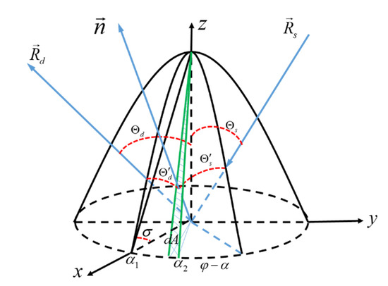
Figure 2.
Radiative transfer model of conical space target.
According to trigonometric functions and geometric relations, we are able to obtain the specific representations of the angle between the incident direction of the solar radiation flux and the normal vector of the space target surface element. The angle between the normal vector of the space target surface element and the direction of the radiation flux, reflected by the space target received by the detector, and the unit effective incidence cross section of the conical space target can be seen in Figure 2.
when both and are less than , the solar radiation energy reflected by the conical space target can be received by the detector [19]. At this time, the following relation is established:
We are able to obtain the value range of the spatial azimuth by the following substitution: , .
According to the trigonometric function, if and are guaranteed to be less than , and and are guaranteed to exist at the same time, then the value range of and is , and the value interval of and is . The value range of has four cases. Next, we analyze the critical conditions of each case, and derive the value interval of and by calculating the value interval of and in each case.
- Case 1:The critical condition for case 1 is , which is discussed in the following two situations: if , then ; if , then . Therefore, in order to satisfy the condition of , the value interval of N is , and the value interval of M is . At the same time, the value interval of and also satisfies the subsequent condition of .
- Case 2:The discussion of the critical condition of in Case 2 is consistent with that of Case 1, but the obtained value interval of and cannot make the subsequent condition of hold. Therefore, Case 2 does not exist.
- Case 3:The critical condition for Case 3 is , which is discussed in the following two situations: if , then ; if , then . Therefore, in order to satisfy the condition of , the value interval of N is , and the value interval of M is . At the same time, the value interval of M and N also satisfies the precondition of .
- Case 4:One critical condition for Case 4 is , as follows: if , then , and the other critical condition is : if , then . Therefore, in order to satisfy the condition of , the value intervals of and are both .
The value range of the phase angle is defined as . According to the literature research, when the phase angle is about , the detector has the best observation conditions for space targets [20]. Therefore, we set the phase angle as , , and , respectively, to explore the effect of the phase angle on the radiation intensity of the space target received by the detector. The inclination of the conical target also has a certain influence on the incident angle of sunlight. Considering the actual processing situation, the conical target inclination is generally set to or . When the conical target inclination and the phase angle are determined, the value of M is determined only by , and the value of N is determined only by . The extreme value of the solar radiation intensity reflected by the space target is related to the range of spatial azimuth. The value interval of the spatial azimuth obtained in each case is different, so the extreme value of the radiation intensity, reflected by the space target received by the detector, also changes in different cases. Taking the phase angle value of and the conical target inclination value of as an example, we simulated a three-dimensional plot of the radiation intensity as a function of and for each case under this example condition (see Figure 3). We then simulated the extreme values of radiation intensity of the space target received by the detector under different conical target inclinations, phase angles, and cases, and the simulation results were shown in Table 1.
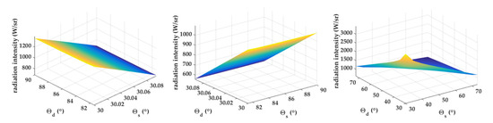
Figure 3.
Under the condition that the value of the phase angle is and the value of the conical target inclination is , this three-dimensional map shows the radiation intensity in each case. (from left to right: Case 1, Case 3, Case 4).

Table 1.
The extreme values of radiation intensity of space targets received by detectors under different conditions.
Cases 1 and 3 have extremely small incident angles or observation angles, which will make it difficult for the detector to capture the space target and aggravate the difficulty of space detection by the detector. In Case 4, whether the observation angle or the incident angle, the angular span is very large, which leaves sufficient time for the detector to capture the space target, which facilitates the space detection of the detector. Therefore, the following analysis will focus on Case 4. From Table 1, we can clearly see that the increase of the conical target inclination will lead to the increase of the minimum value of the radiation intensity. The increase of the phase angle will lead to a decrease in the minimum value of the radiation intensity. We plot Figure 4 to visually represent this changing trend. According to the findings, the radiation intensity reflected by the conical target has a minimum value of 266.6 W/sr when the conical target inclination is and the phase angle is .
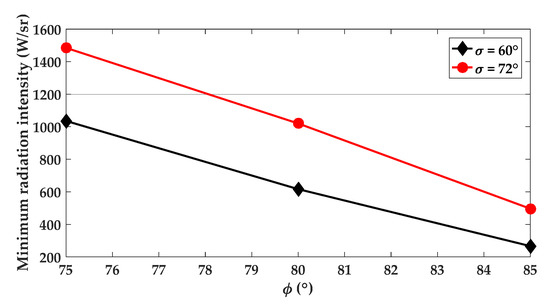
Figure 4.
The minimum values of radiation intensity of space targets received by detectors under different conditions.
4. Determination of Threshold Caliber with Signal-to-Noise Ratio as Evaluation Criteria
The visible detection system’s signal-to-noise ratio (SNR) is a key image quality metric that influences the system’s detection capacity. SNR will be affected by different detecting calibers. As a result, it is critical to investigate the method for estimating the detecting system’s caliber using the SNR as a reference index. Setting the radiation intensity received by the detection system to , the distance between the target and the detection system to , the entrance pupil caliber of the detection system to , the system transmittance to , the quantum efficiency of the image sensor to , the pixel fill factor to , the integration time to , the center wavelength to , and the number of pixels occupied by target imaging to , the number of signal electrons generated by the system during the integration time is expressed as follows:
Photon noise, dark current noise, readout noise, and deep space background noise are all common causes of noise in the detecting system. The variance of the overall system noise is equal to the sum of the variances of all noise contributions, since each noise is independent of the others. The system’s SNR may be calculated using the following definition of SNR:
where is the number of electrons of dark current noise, is the number of electrons of readout noise, and is the number of electrons generated in the deep space background. The sky is a smooth backdrop whose irradiance outside the Earth’s atmosphere is about similar to a 23rd magnitude star, and most of the detection background of the space-based surveillance system is a deep space background. As a result, the total number of electrons produced in the deep space background may be calculated as follows:
where is the irradiance generated by the deep space background. When a visible detection system detects a space target, in order to effectively eliminate the interference of noise, it is usually required that the detection SNR is not less than the threshold SNR ().
The determination of will play an important role in the selection of the entrance pupil caliber. Next, we will study the reasonable range of , based on the detection capability of the system. For the pixel in the image sensor, depending on whether it is imaging the target, there are two hypothetical situations, either that the pixel is not imaging target, or that the pixel is the imaging target. We assume that the detector noise follows a Gaussian distribution with a variance of , while setting to be the average gray value of the pixel not imaging target and to be the average gray value of the pixel imaging target. Therefore, the detection probability and false alarm rate of space targets can be expressed as the following formulas:
where is expressed as the detection threshold, and is expressed as the error function. Similarly, according to the definition of , we are able to obtain another representation of : . By combining Formulas (10), the relationship between the detection probability, the false alarm rate and is expressed as follows:
We set the SNR to change from 1 to 10, and simulate the change of detection probability when the false alarm rate values are “”, “”, “”, “” and “”, respectively. The simulation result is shown in Figure 5.
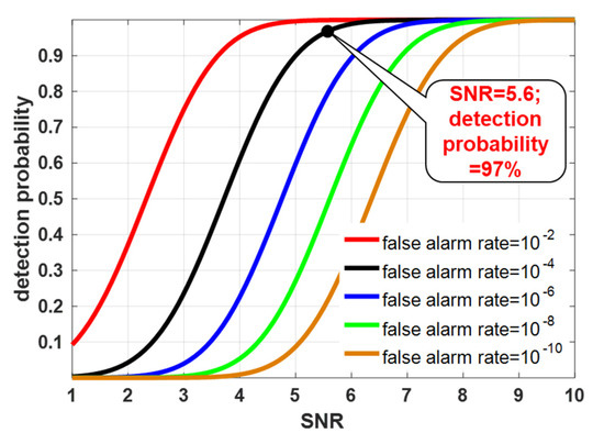
Figure 5.
The relationship between signal-to-noise ratio and detection probability and the false alarm rate.
The simulation findings reveal that increasing the SNR increases detection probability, and the greater the false alarm rate, the higher the rate of SNR growth. As a result, if the system’s detection probability is 97% and the false alarm rate is 0.01%, the system’s SNR must be at least 5.6. The is set to 5.6 to fulfill the criteria of the aforementioned detection capability indicators. According to the Johnson criterion, the system can detect the target when it is imaging 2 pixels on the sensor front; it can roughly classify the target when imaging 3–5 pixels; it can identify the target when imaging 5–10 pixels; and it can identify and confirm the target when the image is larger than 15 pixels. We assume that the system can detect the target at the limit detection distance, and, thus, the number of pixels that can roughly classify the target is set to four. Simultaneous Formulas (6)–(9) can deduce the caliber expression form of the detection system:
We take the SBV sensor on the MSX satellite as an example for verification and analysis. The MSX satellite has an orbital height of 908 km. If the SBV sensor wants to meet the staring observation of the target on the geosynchronous orbit, the working distance of the detection system needs to reach 35,000 km, which is the limit detection distance. The SBV sensor’s parameters were detailed in Table 2.
Table 2.
Values of parameters of the SBV sensor.
We set the radiation intensity value of the space target that the detector can receive as 266.6 W/sr. We may obtain a threshold caliber value of 144.4 mm to fulfill the system detection criteria by plugging the precise values of each parameter into the Formula (12). The actual caliber of the SBV sensor is 150 mm, which proves that the method for determining the caliber of the detection system given in this paper is correct and has reference value.
5. Conclusions
In this paper, the visible light detection of conical space targets was studied, and the method of determining the caliber of the detection system was given. The specific research results are as follows: (1) Under the premise of visible light detection, a three-dimensional conical space target radiation transfer model was constructed. (2) The effects of the phase angle between the solar incident direction and the boresight direction of the detector and the conical target inclination on the radiation intensity of the space target received by the detector were analyzed. (3) Taking the system signal-to-noise ratio as the evaluation standard, the threshold caliber that can meet the detection requirements of the system was obtained, and the SBV sensor was taken as an example to prove that the caliber determination method in this paper is effective. Therefore, through the research method given in this paper, the threshold caliber of the system can be determined similarly in the early stage demonstration of the space-based visible light detection system. On balance, the research in this paper has a certain generalization effect and can be applied to the conventional visible light detection system.
Author Contributions
Conceptualization, D.X.; methodology, D.X. and Y.H.; software, D.X. and Y.H.; validation, C.Y., H.W. and A.X.; formal analysis, D.X.; investigation, D.X. and Y.H.; resources, D.X.; writing—original draft preparation, D.X.; writing—review and editing, Y.H. All authors have read and agreed to the published version of the manuscript.
Funding
This research was funded by the National Natural Science Foundation of China (NSFC), grant number 61805235.
Conflicts of Interest
The authors declare no conflict of interest.
References
- Muntoni, G.; Montisci, G.; Pisanu, T.; Andronico, P.; Valente, G. Crowded Space: A Review on Radar Measurements for Space Debris Monitoring and Tracking. Appl. Sci. 2021, 11, 1364. [Google Scholar] [CrossRef]
- Ren, S.; Yang, X.; Wang, R.; Liu, S.; Sun, X. The Interaction between the LEO Satellite Constellation and the Space Debris Environment. Appl. Sci. 2021, 11, 9490. [Google Scholar] [CrossRef]
- Yang, L.; Xiong, J. Research on agent-based dynamic simulating evaluation of the detection capability for radar netting. In Proceedings of the World Automation Congress, Puerto Vallarta, Mexico, 24–28 June 2012; pp. 89–92. [Google Scholar]
- Pelton, J.N. Tracking of Orbital Debris and Avoidance of Satellite Collisions. In Handbook of Satellite Applications; Springer International Publishing: Cham, Switzerland, 2017. [Google Scholar]
- Frueh, C.; Fielder, H.; Herzog, J. Heuristic and optimized sensor tasking observation strategies with exemplification for geosynchronous objects. J. Guid. Control. Dyn. 2018, 41, 1036–1048. [Google Scholar] [CrossRef] [Green Version]
- Mill, J.D.; Guilmain, B.D. The MSX mission objectives. Johns Hopkins APL Tech. Dig. 1996, 17, 5. [Google Scholar]
- Brinton, T. SBSS Satellite On Track To Enter Operations in Spring. Space News 2011, 22, 7. [Google Scholar]
- Xiaoping, D.U.; Zhi, L.I.; Wang, Y. Research on the Building of US Space Situational Awareness Capability. J. Equip. Acad. 2017, 3, 67–74. [Google Scholar]
- Zeying, T.; Xianfeng, H.; Zongbao, C. Development status and enlightenment of foreign space-based space surveillance systems. Aerosp. Electron. Warf. 2015, 31, 24–26. [Google Scholar]
- Han, X.; Du, L.; Liu, H.-W.; Shao, C.-Y. Classification of micro-motion form of space cone-shaped objects based on time-frequency distribution. Syst. Eng. Electron. 2013, 35, 684–691. [Google Scholar]
- Li, J.; Gao, P.; Shen, M.; Zhao, Y. The capability analysis of the bistatic radar system based on Tianlai radio array for space debris detection. Adv. Space Res. 2019, 64, 1652–1661. [Google Scholar] [CrossRef]
- Yao, D.; Xue, J.; Chen, Z.; Wen, Y.; Jiang, B. Research on the detection capability of space camera. In Selected Papers of the Photoelectronic Technology Committee Conferences, Hefei, Suzhou, Harbin, China, June–July 2015; International Society for Optics and Photonics: Bellingham, WA, USA, 2015; p. 97952E. [Google Scholar]
- Zhangwei, W.; Hao, C.; Han, W. Research on Improving Detection Capability of Small and Medium Scales Based on Dual Polarization Weather Radar. In Proceedings of the 2019 International Conference on Meteorology Observations (ICMO), Chengdu, China, 28–31 December 2019; pp. 1–7. [Google Scholar]
- Zhao, S.; Ruan, N.; Zhuang, X. Detection ability of space-based optical observation system to space debris. In Proceedings of the AOPC 2015: Telescope and Space Optical Instrumentation, Beijing, China, 5–7 May 2015; p. 96780H. [Google Scholar]
- Zhou, Y.-P.; Lu, C.-L.; Yang, L.-L.; Wang, L.-L. Visible light reflection characteristics of space target. J. Harbin Inst. Technol. 2010, 42, 1716–1719. [Google Scholar]
- Wang, M.; Gong, Y.; Ke, X.; Chen, M. The laser radar Doppler spectrum of moving conical target in its spaced orbit observed by ground-based station. Sci. Sin. Technol. 2018, 48, 424–432. [Google Scholar] [CrossRef]
- Wang, C.; Wang, F.; Ye, Z.; Ge, X.; Yin, H.; Cao, Q.; Zhu, J. Analysis on the detection capability of the space-based camera for the space debris. In Proceedings of the Electro-Optical and Infrared Systems: Technology and Applications XIII, Edinburgh, UK, 28–29 September 2016; p. 99870Q. [Google Scholar]
- Shen, W. Optical properties of sun synchronous orbit satellite. J. Beijing Univ. Aeronaut. Astronaut. 2013, 1, 6–10. [Google Scholar]
- Liu, Y.; Chai, J.; Wang, X.; Zhang, B.-L. Visible Characteristics and Calculation of Detecting Distance for Space Target. Infrared Technol. 2009, 31, 23–26. [Google Scholar]
- Zhang, K.K.; Ning-Juan, R.; Dan-Ying, F.U.; Lan, L.Y. Research on space-based visible detecting geometry. Infrared Laser Eng. 2007, 36, 606–609. [Google Scholar]
Publisher’s Note: MDPI stays neutral with regard to jurisdictional claims in published maps and institutional affiliations. |
© 2022 by the authors. Licensee MDPI, Basel, Switzerland. This article is an open access article distributed under the terms and conditions of the Creative Commons Attribution (CC BY) license (https://creativecommons.org/licenses/by/4.0/).