Abstract
In order to further explore the technical difficulties involved in orienting the sparse-aperture imaging system towards practical applications, this paper proposes an optical–mechanical structure design scheme and performance simulation, as well as actual alignment on the beam steering and adjustment structure, which is the core component of the Golay3 sparse-aperture imaging system. The beam steering and adjustment structure corrects the cophasing error by using a combination of mechanical rough adjustment and piezoelectric ceramic precision adjustment. The beam adjustment capability of the beam steering and adjustment structure is analyzed by simulation when the system contains the piston error and the tilt error. The piston error is controlled within 12 μm and the tilt error is controlled within 1200 μrad through the mechanical rough adjustment light path using a large-diameter collimation as the point light source, which realizes the confocality of three beams and mutual interference between two beams. With the USAF1951 resolution test panel display in the distance as the surface target, the adjustable piezoelectric ceramics control the piston error within 55 nm and the tilt error within 0.25 μrad, obtaining the surface target imaging result of the sparse aperture.
1. Introduction
A sparse-aperture imaging system collects beams through multiple small-diameter subapertures, and the beams interfere with each other to achieve high-resolution imaging, thus obtaining a spatial resolution equivalent to that of a large-aperture optical system [1]. However, due to the discrete subapertures and the complex light path structure, the alignment of a sparse-aperture system needs to be conducted at a nanoscale, which brings great challenges to the beam adjustment structure design and the specific alignment [2].
The Golay3 array structure was first proposed by Marcel J. E. Golay in 1970 [3]. In the actual system development, the detection and correction of the phase error between subapertures are important for optical synthetic-aperture telescope systems that have separate mirror structures. One of the important reasons why the six-subaperture synthetic telescope—MMT (Multiple Mirror Telescope) established by the University of Alexandria in 1978—was forced to be replaced with a single-aperture telescope was that the cophasing problem was not being well addressed [4]. A three-aperture test platform Phasar was developed by the Air Force Research Laboratory in 1988. Each sub-telescope in the system has an optical path difference adjuster (OPDA) consisting of a fast steering mirror, and each OPDA has four actuators for the correction of the two-dimensional tilt error and piston error. The four actuators are driven by the signals of the wavefront piston and the tilt sensor [5], enabling the system to realize the cophasing control between the subapertures. However, the system structure is too complex. In 2004, Lockheed Martin developed a novel and adaptable optical telescope comprising an array of nine identical afocal sub-telescopes, which was named the multiple instrument distributed aperture sensor (MIDAS). The light path of each sub-telescope, which consists of five plane mirrors, is an integrated component. A retro-reflecting roof mirror is used to precisely control the optical path length without introducing beam tilt, and can be used to correct small image rotation errors [6,7]. This scheme contains many sub-mirrors, as the processes of beam alignment and cophasing error adjustment are complicated. Salvaggio et al., from the Rochester Institute of Technology, improved the sparse-aperture design framework by the genetic aperture method in 2015 [8,9]. They experimented with a 4f optical system with a sparse-aperture mask plate and introduced the wavefront error into the system, conducting a lot of research on imaging quality [10]. They did not, however, make independent cophasing error adjustments for each aperture. It can be seen that a stable and reliable phase adjustment device is critical to the coefficient aperture system, and the extremely complex design will make it difficult to adjust and control [11]. According to the existing report, it is found that the structure design of the beam control scheme is either too complicated or does not consider the adjustment function. Therefore, it is necessary to design a concise, stable, and practical cophasing error control structure.
Considering that the sparse-aperture imaging system realizes simultaneous imaging by steering in multiple light paths, this paper systematically analyzes the core component—beam steering structure. An integrated design has been achieved for steering and phase control. The mechanical and optical structure and properties are optimized and realize an efficient and stable beam steering and adjustment structure.
2. Requirements for Overall Structure and Beam Adjustment Accuracy of the Golay3 System
2.1. Structure and the Optical Path of the Golay3 System
In order to meet the actual engineering applications, a three-aperture imaging system (Golay3 system) is developed using a modular design scheme. The side view of the light path structure and the three-dimensional model (in CATIA software) are shown in Figure 1a,b, respectively. The system is divided into three main structural modules, namely the subaperture system, the beam steering and adjustment structure, and the synthetic imaging system [12]. The fast steering mirror (FSM) is the core component of the beam steering and adjustment structure. The main system parameters and experimental requirements of the Golay3 system are shown in Table 1.
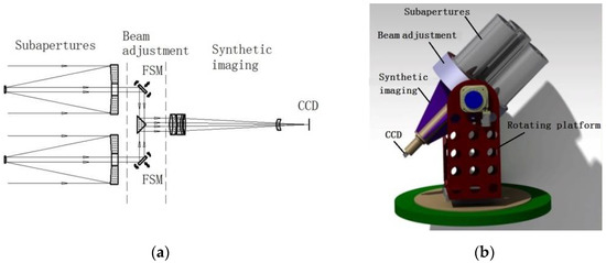
Figure 1.
Golay3 system: (a) side view of the light path structure; (b) three-dimensional model.

Table 1.
Main system parameters and experimental requirements.
As shown in Figure 1a, if there is position error between the subapertures, then the phase of the beams with different passing light paths will be different. It will influence the imaging quality directly. We define the phase error of the beams passing through different subapertures as the cophasing error. The key to the high-resolution observation of the Golay3 sparse-aperture imaging system is the ability to control the cophasing error on the imaging surface within the allowable value range after steering the incident light field between several discrete subapertures. Therefore, the beam steering and adjustment structure must meet the stability of light path steering. Meanwhile, the high accuracy and flexibility of light field adjustment should be achieved. This puts forward higher requirements for the integrated design of the steering and adjusting of the beam steering and adjustment structure [13].
2.2. Theoretical Analyses and Numerical Calculation of the Cophasing Errors
Cophasing errors are mainly piston errors and tilt errors [14], which will cause a serious decline in the image quality. To control the cophasing errors of the sparse-aperture imaging system, we must specifically analyze the influence of the errors.
MTF is a good method to specify the image quality of an optical system and we can start from the pupil function. The total pupil of the sparse-aperture system is a combination of multiple sub-pupils. If the pupil function is expressed with , when there is no cophasing error, the total pupil can be expressed as:
where is the entrance pupil, is the pupil diameter, is the circular domain function, is the central coordinate of the subaperture, is the total number of subapertures, * represents the convolution operation, is the total pupil, is a pupil that contains position information, is the position function of the pupil, and is the central coordinates of the ith sub-pupil.
According to the Fourier transform, the relationship between the point spread function (PSF), the complex amplitude and pupil function is described as follows:
The modulation transfer function (MTF) of the sparse-aperture system can be derived from the PSF:
When the system contains both piston and tilt errors, the pupil function can be expressed as:
where represents cophasing errors and is the piston error of the subaperture relative to the reference subaperture. and are the slope of the subaperture along the X-axis and Y-axis of the ideal plane, respectively. Using the above relationship, the MTF of the system can be calculated through a numerical calculation, as shown in Figure 2.
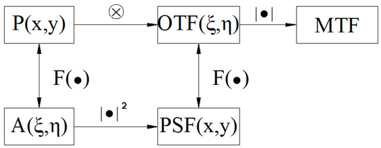
Figure 2.
The calculation flow chart.
For the Golay3 three-aperture system, the change in the MTF of one subaperture is assigned different cophasing errors, which can be simulated in MATLAB [15]. In numerical calculations, the subaperture size is d = 200 mm and the working wavelength is λ = 535 nm. The coordinate positions (x, y) of the three subapertures can be calculated by the designed filling factor of 0.369. The MTF of the system can be obtained after the piston error of the subaperture is successively loaded with 0λ, 0.25λ, 0.5λ, 0.75λ and 1λ, as shown in Figure 3.
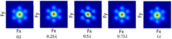
Figure 3.
MTF for different piston errors.
When tilt errors loaded with 0.25 μrad, 0.50 μrad, 0.75 μrad, and 1 μrad are assigned to one subaperture, the MTFs are shown in Figure 4.
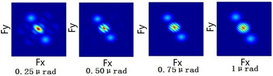
Figure 4.
MTF for different tilt errors.
When both the piston error (0.5λ) and the tilt error are applied to one subaperture, Figure 5 shows the MTF changing rule.
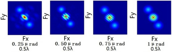
Figure 5.
MTF with both piston error and tilt error.
The piston error is mainly caused by the optical path difference along the exit pupil plane axis and is only related to each sub-beam. The excessive piston error reduces the system resolution to a single-aperture level. The maximum allowable piston error is about , and it will be 55 nm if the operating wavelength is 550 nm. The tilt error is mainly caused by the rotation of the pupil surface in the x- and y-axes, which upsets the parallelism of the sub-beam wave surface. The maximum allowable value of the tilt error is 0.25 μrad.
In addition to the point source, the image source is also simulated and analyzed. The objective image meets the convolution relationship, and the obtained image can be expressed as [16]:
where is the image acquired by the camera, is the ideal image, represents the convolution, is the point spread function of the sparse-aperture system, and is the noise distribution. The image without any error can be obtained by a convolution operation using an object-image resolution test pattern in MATLAB software, as shown in Figure 6 [17,18], in which we mark the spatial frequency of a group of lines.
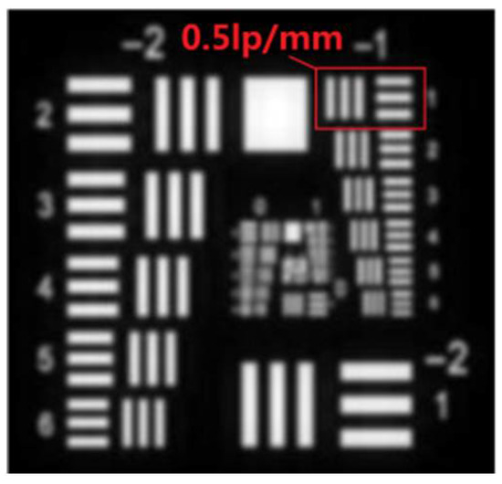
Figure 6.
Simulated imaging without cophasing error.
The imaging results, when the piston errors of one aperture are and , respectively, are shown in Figure 7.
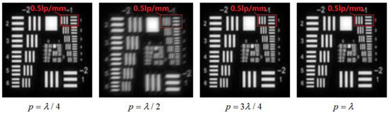
Figure 7.
Simulated imaging with different piston errors.
When the piston error is 0, the imaging result is the same as the ideal imaging result. The imaging result becomes increasingly blurred when the piston error increases from 0 to . The imaging result gradually becomes clear when the piston error increases from to , therefore, the piston error is periodic.
Similarly, the imaging results when the tilt errors of one aperture are respectively and , are shown in Figure 8.
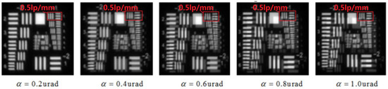
Figure 8.
Simulated imaging with different tilt errors.
It can be seen from the figures that the larger the tilt error is, the farther the image of the subaperture deviates from the initial position.
According to the analysis result, cophasing error control is the key to system design. The steering control structure of the beam in this system undertakes the steering convergence of beams received by subapertures and the relative phase adjustment between the beams, so it is a key part of the design and assembly of the entire system.
3. Design of Beam Steering and Adjustment Structure
3.1. Structure Design Scheme
Based on the three-aperture layout, a 45° inclined planar mirror and a 45° triangular cone mirror are used to realize the steering of the light path, as shown in Figure 9. The triangular cone mirror is mounted on a fine-adjusting precision platform adjustable for 3 degrees of freedom (XYθ) to ensure that the triangular cone is at the center of the three subapertures. The planar mirror is mounted on a piezoelectric ceramic (PZT) micro-displacement actuator and fixed with a bracket, which together constitutes a fast steering mirror (FSM) structure to adjust the piston error and tilt error of the light path.
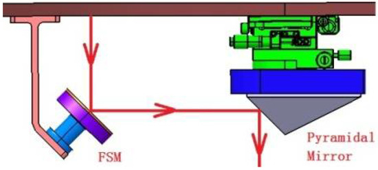
Figure 9.
Three-dimensional model of the beam steering and adjustment structure.
The key issue considered in the design is the adjustment accuracy of the structure, which is also the guarantee of the system imaging quality. The entire adjustment structure is divided into rough adjustment and precision adjustment; rough adjustment meets the adjustment range of the light path, and precision adjustment meets the cophasing error control requirement. The mechanical adjustment structure of “three screws for pull and three screws for push” is adopted for the FSM rough adjustment, as shown in Figure 10.
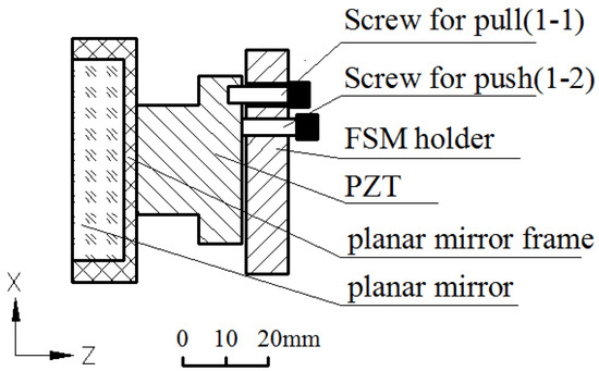
Figure 10.
FSM structure.
The FSM precision adjustment is driven by a PZT (PI S316) with a Z-direction translation stroke of 12 μm, a closed-loop resolution of 0.4 nm, a tilt angle stroke of 1200 μrad, and a resolution of 0.1 μrad.
In order to ensure that the FSM does not jitter or vibrate during the motion of the piezoelectric ceramics, we analyzed the first- and tenth-order vibration modes of the FSM structure by using ANSYS Workbench software, as shown in Figure 11a,b. In addition, the harmonic response analysis results of the FSM structure are supplemented, as shown in Figure 11c,d. The vibration frequency of piezoelectric ceramics is known to be 3400 Hz from the product presentation. Therefore, the FSM structure will not resonate during the motion of the piezoelectric ceramics, and the dynamic stiffness of the system meets the operating requirements [19].
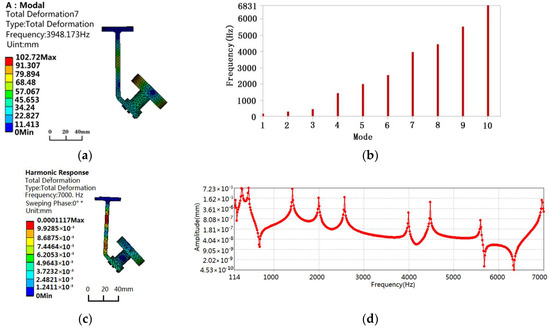
Figure 11.
Vibration analysis of the FSM structure: (a) 7th order vibration mode, (b) 1st–10th order mode natural frequency, (c) strain analysis of harmonic response in 7000 Hz, and (d) frequency–displacement curve of harmonic response.
3.2. Analysis of Beam Adjustment Capability
According to the design scheme of the beam steering and adjustment structure, the sub-light path piston error is controlled at 12 μm and the tilt error is controlled at 1200 μrad through the “Three Screws for Pull and Three Screws for Push” structure of the FSM rough adjustment. The piston error and tilt error are then precisely adjusted by the FSM piezoelectric ceramics. This section will simulate the correction of the piston error and tilt error of the system.
3.2.1. Piston Error Correction Simulation
The Power UMAC programmable multi-axis motion controller from Delta Tau Data System Inc. is adopted as the system controller module. In the control software system, each piece of piezoelectric ceramic corresponds to three commands: displacement in the Z-axis, rotation around the X-axis, and rotation around the Y-axis. The Z-axis displacement command is used to adjust the piston error; the X-axis and Y-axis rotation commands are used to adjust the tilt error.
When there is no piston error in the subaperture, the light path is , as shown by the solid lines in Figure 12. When there is a piston error in the subaperture, the light path is , as shown by the dotted lines in Figure 12, and the optical path difference is . Corresponding adjustments are made by the FSM to compensate for the piston error and ensure a constant optical path length. The piston motion of the FSM is driven by piezoelectric ceramics, and the compensation is set as . As can be seen from the figure, regardless of the value of , there is still . Therefore, the piston error of the subaperture can be compensated for when the motion of enables or . In order to realize , there shall be °, i.e., when the compensation is °, there is . Therefore, when there is a piston error in the subaperture, the Z-axis motion that the piezoelectric ceramics can compensate for in the piston error is:
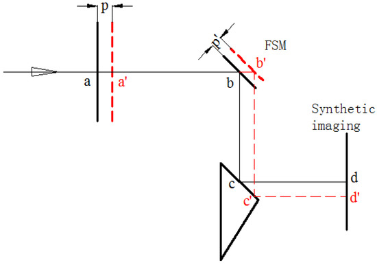
Figure 12.
Comparison of optical paths when 0 piston error and p piston error.
With the piston error image as the correction object, according to Formula (1), the piezoelectric ceramic motion for correcting the piston error is:
The piston error correction commissioning is carried out by gradually adjusting the Z-axis displacement of the piezoelectric ceramics from to , and the corrected image is shown in Figure 13.
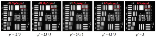
Figure 13.
Simulated imaging of piston error correction.
It can be seen from Figure 11 that the imaging effect is equivalent to the ideal situation when .
3.2.2. Tilt Error Correction Simulation
When there is no tilt error in the subaperture, the light path is , as shown by the solid lines in Figure 14. When there is a tilt error in the subaperture, the light path is , as shown by the dotted lines in Figure 14. B1B2 is an FSM, and its tilting motion is driven by piezoelectric ceramics, with a compensation of .
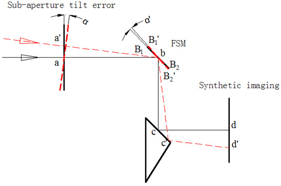
Figure 14.
Comparison of optical paths with 0 tilt error and α tilt error.
According to the relationship in the figure, , we can derive , i.e., . Therefore, when there is a tilt error in the subaperture, the tilt angle stroke that the piezoelectric ceramics can compensate for in the tilt error is:
With the tilt error image as the correction object, according to Formula (8), the piezoelectric ceramic motion for correcting the tilt error is:
The tilt error correction commissioning is carried out by gradually adjusting the tilt of piezoelectric ceramics from to , and the corrected image is shown in Figure 15. It can be seen from Figure 14 that the tilt error is corrected when .
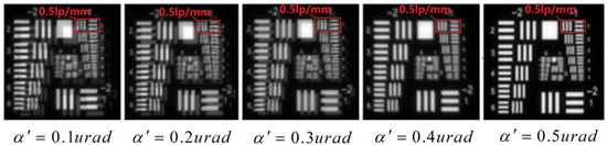
Figure 15.
Tilt error correction simulation.
4. Alignment Experiment
After confirming the effectiveness of the design scheme in cophasing error adjustment by simulation, this scheme is applied to the actual Golay3 sparse-aperture imaging system. The fact that the three sub-light paths have their own optic axes is the biggest difficulty in the alignment. In order to ensure the accuracy requirements of the system, the entire alignment process can be divided into three steps: alignment of the single-beam FSM structure, confocality of the three-beam steering structure, and correction of the cophasing error of the system.
During alignment, manual rough adjustment is used to match with the PZT precision adjustment. The alignment principle and process are shown in Figure 16a,b. After repeated iteration until the interference detection results meet the theoretical design requirements, the alignment results of the three light paths of the beam steering are shown in Figure 16c. In the light path where the subaperture 1 is located: RMS = 0.08λ, and PV = 0.55λ. In the light path where the subaperture 2 is located: RMS = 0.10λ, and PV = 0.67λ. In the light path where the subaperture 3 is located: RMS = 0.08λ, and PV = 0.54λ (λ = 633 nm). The wave aberration RMS is superior to λ/8 for all three subapertures, and the alignment results meet the theoretical design requirements.
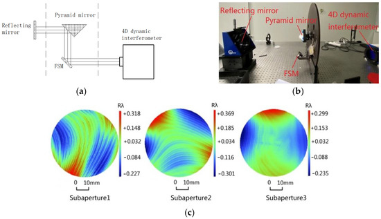
Figure 16.
Interferometric testing: (a) the principle, (b) the alignment process, and (c) alignment results displayed in the interferometer through PZT precision adjustment.
After the beam alignment is determined through the wave aberration analysis with the interferometer, the next step is to make the three subaperture beams converge to a point on the CCD through the synthetic imaging system by coarse adjustment, so that the three beams can be confocal. Through rough adjustment of the cophasing error, the piston error is controlled within 12 μm and the tilt error is controlled within 1200 μrad. After the alignment detection is performed for the subapertures, synthetic imaging system, beam steering, and adjustment structure, respectively, the three subapertures and the synthetic imaging system are installed on the connecting plate of the beam steering and adjustment structure. The system is installed on a pitchable 2D rotating frame. The physical prototype of the entire sparse-aperture imaging system is assembled, as shown in Figure 17a.
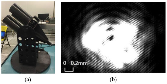
Figure 17.
Rough adjustment of cophasing error: (a) Golay3 physical prototype; (b) point source experiment.
The infinite point target is simulated using a large-diameter collimation, and the CCD image surface interference diagram is used as the detection object [20]. Rough adjustment is made for the FSM mechanical structure of the three beams, so that the light spots of subaperture 1, subaperture 2, and subaperture 3 can interfere with each other. The interference pattern is shown in Figure 17b.
Since the field of view of the subaperture is 0.2°, the center distance of the three subapertures is 320 mm. When the object distance is infinite, the fields of view of the three subapertures nearly coincide exactly with each other. When the object distance is finite, the field of view of the three subapertures can only overlap locally. The USAF1951 resolution test panel display 70 m away from the system is used as the surface target. The superimposed image of the field of view of the three subapertures is shown in Figure 17a. This synthetic image contains relatively large piston errors and tilt errors. By referring to the image of subaperture 1 in CCD, the PZTs of subaperture 2 and subaperture 3 are adjusted, respectively, and the piston error and tilt error of subaperture 2 and subaperture 3 are corrected. The synthetic image obtained after correction of the cophasing error is shown in Figure 18b.
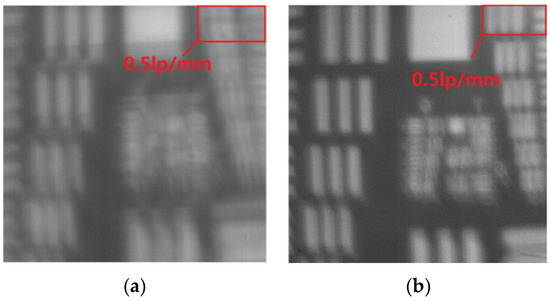
Figure 18.
Results of image source experiment: (a) synthetic image with cophasing error; (b) synthetic image after correction of cophasing error.
It can be seen from the test results that the tilt error and piston error of the system are corrected through adjustments by the beam steering and adjustment structure. By comparing the simulation results, it can be judged that the system piston error is , namely within 55 nm, and that the tilt error is within 0.25 μrad. As the target is small and far from the three-aperture system, the light intensity on the CCD is weak and the brightness of the resulting synthetic image is low. Due to the residual surface error of each mirror, the imaging resolution decreases, leading to a certain gap between the final image and the theoretical simulation.
5. Conclusions
This paper presents a Golay3 sparse-aperture system for practical engineering applications. The design scheme of the beam steering and adjustment structure is described in detail and the actual adjustment capability is simulated. Wave aberration detection is carried out on the three light paths of the beam steering and adjustment structure. The RMS of the three light paths reaches 0.08λ, 0.10λ, and 0.08λ, respectively. After the overall system assembly is completed, the infinite point target is simulated with a large-diameter collimation, and the CCD image surface imaging diagram is used as the detection object. Through rough adjustment, point target imaging is achieved, and the converged beams of the three subapertures interfere with each other on the CCD image surface. With the USAF1951 resolution test panel display 70 m away from the system as the surface target and the image of subaperture 1 on the CCD as the reference, the PZTs of subaperture 2 and subaperture 3 are adjusted, respectively, to obtain the synthetic image after the correction of the cophasing error. The beam steering and adjustment structure proposed in this paper is the first time it is applied to the sparse aperture system, and it can effectively control the piston error within 55 nm and the tilt error within 0.25 μrad. Compared with other alternatives, it has the advantages of simple structure, convenient operation, and high precision. Furthermore, this design can be applied to other sparse-aperture systems.
Author Contributions
Conceptualization, J.Q. and Y.T.; methodology, Y.T.; software, X.H.; validation, X.W. and H.L.; formal analysis, X.H.; investigation, J.Q.; resources, X.W.; data curation, H.L.; writing—original draft preparation, J.Q.; writing—review and editing, R.Z.; visualization, X.H.; supervision, R.Z.; project administration, X.W.; funding acquisition, R.Z. All authors have read and agreed to the published version of the manuscript.
Funding
This work was supported by the Major Science and Technology Projects in Sichuan Province (2019ZDZX0038).
Institutional Review Board Statement
Not applicable.
Informed Consent Statement
Not applicable.
Data Availability Statement
The data that support the findings of this study are available from the authors upon reasonable request.
Conflicts of Interest
The authors declare no conflict of interest.
References
- Meinel, A.B. Aperture Synthesis Using Independent Telescopes. Appl. Opt. 1970, 9, 2501. [Google Scholar] [CrossRef] [PubMed]
- An, Q.; Wu, X.; Lin, X.; Ming, M.; Wang, J.; Chen, T.; Zhang, J.; Li, H.; Chen, L.; Tang, J.; et al. Large segmented sparse aperture collimation by curvature sensing. Opt. Express 2020, 28, 40176–40187. [Google Scholar] [CrossRef] [PubMed]
- Golay, M.J.E. Point Arrays Having Compact, Nonredundant Autocorrelations. J. Opt. Soc. Am. 1971, 61, 272–273. [Google Scholar] [CrossRef]
- McCray, W.P. What Makes a Failure? Designing a New National Telescope. Appl. Opt. 2001, 42, 265–291. [Google Scholar] [CrossRef]
- Fender, J.S.; Carreras, R.A. Demonstration of an Optically Phased Telescope Array. Opt. Eng. 1988, 27, 279706. [Google Scholar] [CrossRef]
- Smith, E.H.; De Leon, E.; Dean, P.; Deloumi, J.; Duncan, A.; Hoskins, W.; Kendrick, R.; Mason, J.; Page, J.; Phenis, A.; et al. Multiple instrument distributed aperture sensor (MIDAS) testbed. Proc. SPIE 2005, 9, 58821F1–58821F13. [Google Scholar] [CrossRef]
- Pitman, J.T.; Duncan, A.; Stubbs, D.; Sigler, R.D.; Kendrick, R.L.; Smith, E.H.; Mason, J.E.; Delory, G.; Lipps, J.H.; Manga, M.; et al. Remote sensing space science enabled by the multiple instrument distributed aperture sensor (MIDAS) concept. Proc. SPIE 2004, 5555, 301–311. [Google Scholar] [CrossRef]
- Salvaggio, P.S.; Schott, J.R.; McKeown, D.M. Genetic apertures: An improved sparse aperture design framework. Appl. Opt. 2016, 55, 3182–3191. [Google Scholar] [CrossRef] [PubMed]
- Salvaggio, P.S.; Schott, J.R.; McKeown, D.M. Laboratory validation of a sparse aperture image quality model. Appl. Opt. 2015, 8617, 861708-1–861708-11. [Google Scholar] [CrossRef]
- Salvaggio, P.S. Image quality modeling and optimization for Nonconventional Aperture Imaging Systems. Ph.D. Thesis, Rochester Institute of Technology, Rochester, UK, 2016. [Google Scholar]
- Zhang, L.; Liu, M.; Zhao, Y.; Dong, L.; Li, X.; Du, H. The optimal design of a binaural sparse-aperture system. Results Phys. 2020, 16, 102970. [Google Scholar] [CrossRef]
- Jiang, A.; Wang, S.; Dong, Z.; Xue, J.; Wang, J.; Dai, Y. Wide-band white light sparse-aperture Fizeau imaging interferometer testbed for a distributed small-satellites constellation. Appl. Opt. 2018, 57, 2736–2746. [Google Scholar] [CrossRef] [PubMed]
- Jiang, A.; Dong, Z.; Xue, J.; Dai, Y.; Wang, S.; Wang, J. Detection and closed-loop control of piston errors for a Fizeau imaging interferometer. Appl. Opt. 2020, 59, 3892–3900. [Google Scholar] [CrossRef] [PubMed]
- Miller, N.J.; Dierking, M.P.; Duncan, B.D. Optical sparse aperture imaging. Appl. Opt. 2007, 46, 5933–5943. [Google Scholar] [CrossRef] [PubMed]
- Wu, Q.; Fan, J.; Wu, F.; Zhao, J.; Qian, L. Error analysis of the Golay3 optical imaging system. Appl. Opt. 2013, 52, 2966–2973. [Google Scholar] [CrossRef]
- Ma, X.; Xie, Z.; Ma, H.; Xu, Y.; Ren, G.; Liu, Y. Piston sensing of sparse aperture systems with a single broadband image via deep learning. Opt. Express 2019, 27, 16058–16070. [Google Scholar] [CrossRef] [PubMed]
- Wang, D.; Han, J.; Liu, H.; Tao, S.; Fu, X.; Guo, H. Experimental study on imaging and image restoration of optical sparse aperture systems. Opt. Eng. 2007, 46, 103201–103208. [Google Scholar] [CrossRef]
- Hui, M.; Li, X.; Zhang, H.; Liu, M.; Dong, L.; Kong, L.; Zhao, Y. Image restoration of optical sparse aperture systems based on a dual target network. Results Phys. 2020, 19, 103429–103441. [Google Scholar] [CrossRef]
- Doyle, K.B. Design of optical structures for maximum fundamental frequency. Proc. SPIE 1993, 1998, 50–59. [Google Scholar] [CrossRef]
- Xie, Z.; Ma, H.; Qi, B.; Ren, G.; Shi, J.; He, X.; Tan, Y.; Dong, L.; Wang, Z. Experimental demonstration of enhanced resolution of a Golay3 sparse-aperture telescope. Chin. Opt. Lett. 2017, 15, 041101–41104. [Google Scholar] [CrossRef] [Green Version]
Publisher’s Note: MDPI stays neutral with regard to jurisdictional claims in published maps and institutional affiliations. |
© 2022 by the authors. Licensee MDPI, Basel, Switzerland. This article is an open access article distributed under the terms and conditions of the Creative Commons Attribution (CC BY) license (https://creativecommons.org/licenses/by/4.0/).