
An Improved Static Residual Force Algorithm and Its Application in Cable Damage Identification for Cable-Stayed Bridges


Abstract
:1. Introduction
2. Theoretical Development
2.1. Static Residual Force Algorithm
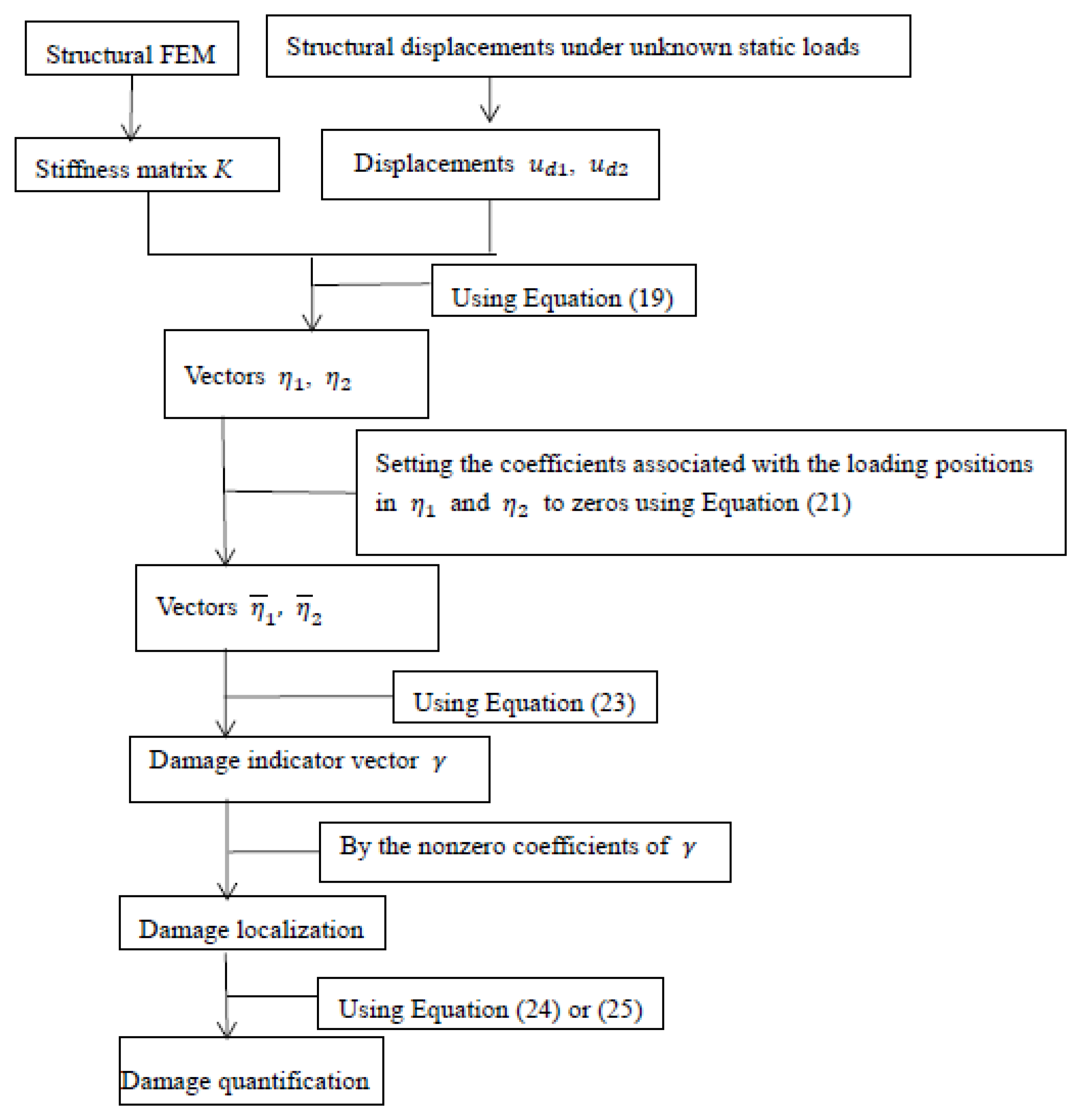
2.2. Improvement of Static Residual Force
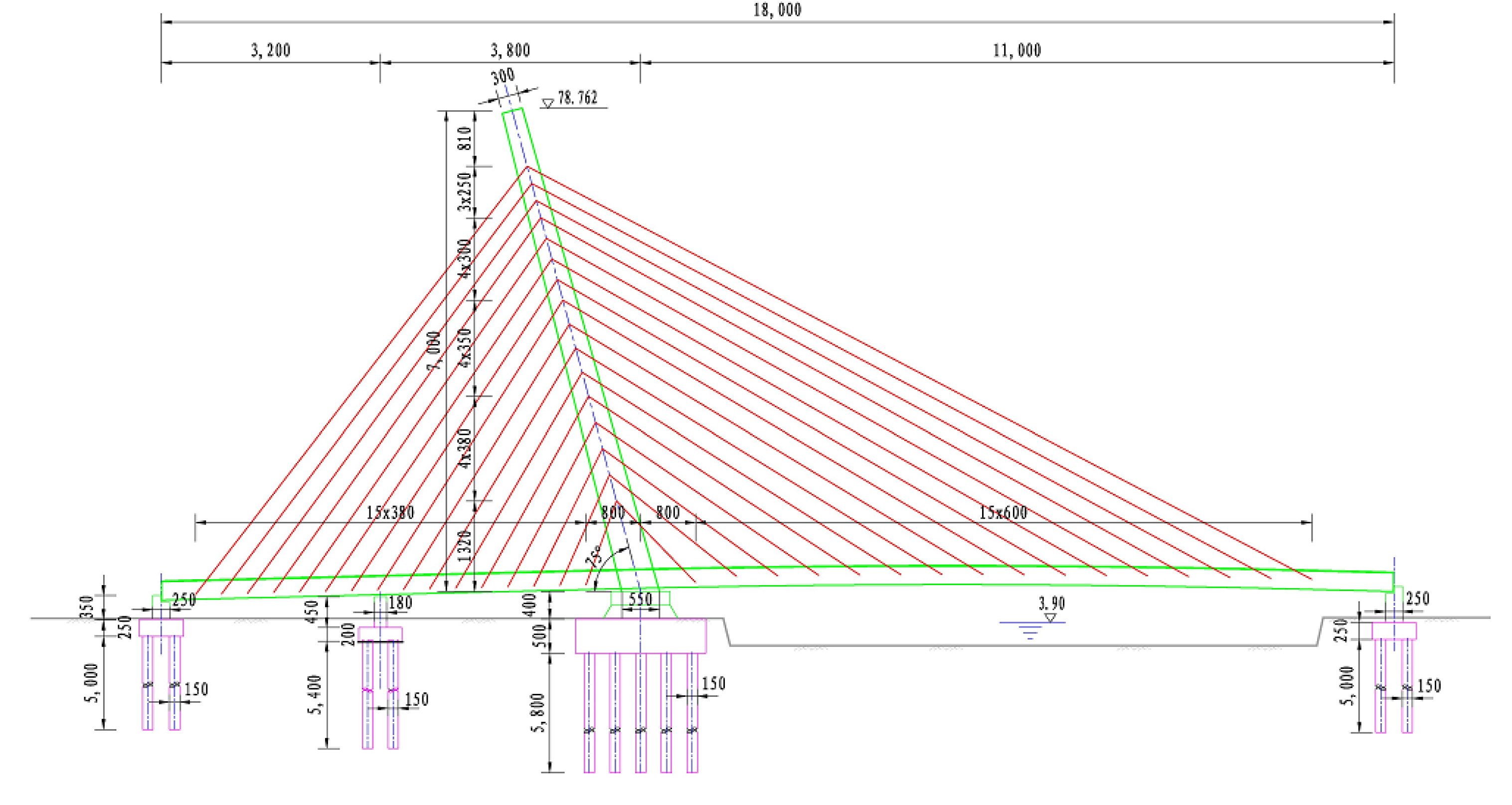
3. Numerical Example
4. Conclusions
Author Contributions
Funding
Institutional Review Board Statement
Informed Consent Statement
Data Availability Statement
Conflicts of Interest
References
- Ko, J.M.; Sun, Z.G.; Ni, Y.Q. Multi-stage identification scheme for detecting damage in cable-stayed Kap-Shui-Mun Bridge. Eng. Struct. 2002, 24, 857–868. [Google Scholar] [CrossRef]
- Zhu, J.; Xiao, R. Damage identification of a large-span concrete cable-stayed bridge based on genetic algorithm. Front. Archit. Civ. Eng. China 2007, 1, 170–175. [Google Scholar] [CrossRef]
- Ni, Y.Q.; Zhou, H.F.; Chan, K.C.; Ko, J.M. Modal flexibility analysis of cable-stayed Ting Kau Bridge for damage identification. Comput.-Aided Civ. Infrastruct. Eng. 2008, 23, 223–236. [Google Scholar] [CrossRef]
- Hou, L.Q.; Zhao, X.F.; Han, R.C. Optimal sensor placement for stay cable damage identification of cable-stayed bridge under uncertainty. Int. J. Distrib. Sens. Netw. 2013, 9, 361594. [Google Scholar] [CrossRef]
- Mehrabi, A.B.; Telang, N.M. Cable-stayed bridge performance evaluation—Lessons from the field. In Proceedings of the 2003 ASCE Structures Congress, Seattle, WA, USA, 28 May–1 June 2003. [Google Scholar]
- Ho, H.N.; Kim, K.D.; Park, Y.S.; Young, S.P.; Jong, J.L. An efficient image-based damage detection for cable surface in cable-stayed bridges. Ndt E Int. 2013, 58, 18–23. [Google Scholar] [CrossRef]
- Mehrabi, A.B. In-service evaluation of cable-stayed bridges, overview of available methods and findings. J. Bridge Eng. 2006, 11, 716–724. [Google Scholar] [CrossRef]
- Liu, X.; Xiao, J.; Wu, B.; He, C.F. A novel sensor to measure the biased pulse magnetic response in steel stay cable for the detection of surface and internal flaws. Sens. Actuators A Phys. 2018, 269, 218–226. [Google Scholar] [CrossRef]
- Zhang, S.; Shen, R.; Dai., K.; Wang, L.; Roeck, G. A methodology for cable damage identification based on wave decomposition. J. Sound Vib. 2019, 442, 527–551. [Google Scholar] [CrossRef]
- Kildashti, K.; Alamdari, M.M.; Kim, C.W.; Gao, W.; Samali, B. Drive-by-bridge inspection for damage identification in a cable-stayed bridge: Numerical investigations. Eng. Struct. 2020, 223, 110891. [Google Scholar] [CrossRef]
- Huang, J.; Li, D.; Li, H.; Song, G.; Liang, Y. Damage identification of a large cable-stayed bridge with novel cointegrated Kalman filter method under changing environments. Struct. Control Health Monit. 2018, 25, e2152. [Google Scholar] [CrossRef]
- An, Y.; Chatzi, E.; Sim, S.H.; Laflamme, S.; Blachowski, B.; Ou, J. Recent progress and future trends on damage identification methods for bridge structures. Struct. Control Health Monit. 2019, 26, e2416. [Google Scholar] [CrossRef]
- Radzieński, M.; Krawczuk, M.; Palacz, M. Improvement of damage detection methods based on experimental modal parameters. Mech. Syst. Signal Process. 2011, 25, 2169–2190. [Google Scholar] [CrossRef]
- Kopsaftopoulos, F.P.; Fassois, S.D. A functional model based statistical time series method for vibration based damage detection, localization, and magnitude estimation. Mech. Syst. Signal Processing 2013, 39, 143–161. [Google Scholar] [CrossRef]
- Sung, S.H.; Jung, H.J.; Jung, H.Y. Damage detection for beam-like structures using the normalized curvature of a uniform load surface. J. Sound Vib. 2013, 332, 1501–1519. [Google Scholar] [CrossRef]
- Xiang, J.; Matsumoto, T.; Wang, Y.; Jiang, Z. Detect damages in conical shells using curvature mode shape and wavelet finite element method. Int. J. Mech. Sci. 2013, 66, 83–93. [Google Scholar] [CrossRef]
- Xu, Z.D.; Liu, M.; Wu, Z.; Zeng, X. Energy damage detection strategy based on strain responses for long-span bridge structures. J. Bridge Eng. 2011, 16, 644–652. [Google Scholar] [CrossRef]
- Yi, T.H.; Li, H.N.; Sun, H.M. Multi-stage structural damage diagnosis method based on “energy-damage” theory. Smart Struct. Syst. 2013, 12, 345–361. [Google Scholar] [CrossRef]
- Cha, Y.J.; Buyukozturk, O. Structural damage detection using modal strain energy and hybrid multiobjective optimization. Comput. Aided Civ. Infrastruct. Eng. 2015, 30, 347–358. [Google Scholar] [CrossRef]
- Khorram, A.; Bakhtiari-Nejad, F.; Rezaeian, M. Comparison studies between two wavelet based crack detection methods of a beam subjected to a moving load. Int. J. Eng. Sci. 2012, 51, 204–215. [Google Scholar] [CrossRef]
- Roveri, N.; Carcaterra, A. Damage detection in structures under traveling loads by Hilbert–Huang transform. Mech. Syst. Signal Process. 2012, 28, 128–144. [Google Scholar] [CrossRef]
- Cavadas, F.; Smith, I.F.C.; Figueiras, J. Damage detection using data-driven methods applied to moving-load responses. Mech. Syst. Signal Processing 2013, 39, 409–425. [Google Scholar] [CrossRef] [Green Version]
- Chung, J.L.; Yu, T.H. Vibration analysis of an inhomogeneous string for damage detection by wavelet transform. Int. J. Mech. Sci. 2002, 44, 745–754. [Google Scholar]
- Lepidi, M.; Gattulli, V.; Vestroni, F. Damage identification in elastic suspended cables through frequency measurement. J. Vib. Control 2009, 15, 867–896. [Google Scholar] [CrossRef]
- Wang, X.; Hu, N.; Fukunaga, H.; Yao, Z. Structural damage identification using static test data and changes in frequencies. Eng. Struct. 2001, 23, 610–621. [Google Scholar] [CrossRef]
- Sanayei, M.; Onipede, O. Assessment of structures using static test data. AIAA J. 1991, 29, 1156–1179. [Google Scholar] [CrossRef]
- Banan, M.R.; Banna, M.R.; Hjelmstad, K.D. Parameter estimation of structures from static response, Ⅰ: Computational aspects. J. Struct. Eng. 1994, 120, 3243–3258. [Google Scholar] [CrossRef]
- Banan, M.R.; Banna, M.R.; Hjelmstad, K.D. Parameter estimation of structures from static response, Ⅱ: Numerical simulation studies. J. Struct. Eng. 1994, 120, 3259–3283. [Google Scholar] [CrossRef]
- Hjelmstad, K.D.; Shin, S. Damage detection and assessment of structures from static response. J. Eng. Mech. 1997, 123, 568–576. [Google Scholar] [CrossRef]
- Chou, J.H.; Ghaboussi, J. Genetic algorithm in structural damage detection. Comput. Struct. 2001, 79, 1335–1353. [Google Scholar] [CrossRef]
- Bakhtiari-Nejad, F.; Rahai, A.; Esfandiari, A. A structural damage detection method using static noisy data. Eng. Struct. 2005, 27, 1784–1793. [Google Scholar] [CrossRef]
- Chen, X.Z.; Zhu, H.P.; Chen, C.Y. Structural damage identification using test static data based on grey system theory. J. Zhejiang Univ. Sci. 2005, 6A, 790–796. [Google Scholar] [CrossRef]
- Kouchmeshky, B.; Aquino, W.; Bongard, J.C.; Lipson, H. Co-evolutionary algorithm for structural damage identification using minimal physical testing. Int. J. Numer. Methods Eng. 2007, 69, 1085–1107. [Google Scholar] [CrossRef] [Green Version]
- Yang, Q.W.; Liu, J.K.; Sun, B.X.; Liang, C.F. Damage localization for beam structure by moving load. Adv. Mech. Eng. 2017, 9, 1–6. [Google Scholar] [CrossRef] [Green Version]
- Hua, X.G.; Ni, Y.Q.; Chen, Z.Q.; Ko, J.M. Structural damage detection of cable-stayed bridges using changes in cable forces and model updating. J. Struct. Eng. 2009, 135, 1093–1106. [Google Scholar] [CrossRef]
- Lin, S.W.; Yi, T.H.; Li, H.N.; Ren, L. Damage detection in the cable structures of a bridge using the virtual distortion method. J. Bridge Eng. 2017, 22, 04017039. [Google Scholar] [CrossRef]
- Yang, Q.W.; Zhou, C.; Li, C.H.; Luo, S. Structural damage assessment based on static residual force vector. Chin. J. Comput. Mech. 2021, 38, 625–630. [Google Scholar]
- Lepidi, M.; Gattulli, V.; Vestroni, F. Static and dynamic response of elastic suspended cables with damage. Int. J. Solids Struct. 2007, 44, 8194–8212. [Google Scholar] [CrossRef] [Green Version]
- Jin, W.M.; Yang, Q.W.; Zhao, W. Damage diagnosis by an improved static-based method. J. Mech. Strength 2012, 34, 190–193. [Google Scholar]

| Elements | Elastic Modulus | Density | Cross Sectional Area | Moment of Inertia |
|---|---|---|---|---|
| Cable | 200 GPa | 7800 kg/m3 | 4.657 × 10⁻³ m2 | / |
| Pylon | 200 GPa | 7800 kg/m3 | 0.31 m2 | 0.437 |
| Box girder | 200 GPa | 7800 kg/m3 | 0.75 m2 | 1.26 |
| Cable Element Number (From Left to Right) | Corresponding Nodes | Corresponding DOFs |
|---|---|---|
| 1 | 1, 17 | 1, 2, 3, 49, 50 |
| 2 | 2, 18 | 4, 5, 6, 51, 52 |
| 3 | 3, 19 | 7, 8, 9, 53, 54, 55 |
| 4 | 4, 20 | 10, 11, 12, 56, 57, 58 |
| 5 | 5, 21 | 13, 14, 15, 59, 60, 61 |
| 6 | 6, 22 | 16, 17, 18, 62, 63, 64 |
| 7 | 7, 23 | 19, 20, 21, 65, 66, 67 |
| 8 | 8, 24 | 22, 23, 24, 68, 69, 70 |
| 9 | 9, 25 | 25, 26, 27, 71, 72, 73 |
| 10 | 10, 26 | 28, 29, 30, 74, 75, 76 |
| 11 | 11, 27 | 31, 32, 33, 77, 78, 79 |
| 12 | 12, 28 | 34, 35, 36, 80, 81, 82 |
| 13 | 13, 29 | 37, 38, 39, 83, 84, 85 |
| 14 | 14, 30 | 40, 41, 42, 86, 87, 88 |
| 15 | 15, 31 | 43, 44, 45, 88, 89, 90 |
| 16 | 16, 32 | 46, 47, 48, 92, 93, 94 |
| 17 | 16, 33 | 46, 47, 48, 95, 96, 97 |
| 18 | 15, 34 | 43, 44, 45, 98, 99, 100 |
| 19 | 14, 35 | 40, 41, 41, 101, 102, 103 |
| 20 | 13, 36 | 37, 38, 39, 104, 105, 106 |
| 21 | 12, 37 | 34, 35, 36, 107, 108, 109 |
| 22 | 11, 38 | 31, 32, 33, 110, 111, 112 |
| 23 | 10, 39 | 28, 29, 30, 113, 114, 115 |
| 24 | 9, 40 | 25, 26, 27, 116, 117, 118 |
| 25 | 8, 41 | 22, 23, 24, 119, 120, 121 |
| 26 | 7, 42 | 19, 20, 21, 122, 123, 124 |
| 27 | 6, 43 | 16, 17, 18, 125, 126, 127 |
| 28 | 5, 44 | 13, 14, 15, 128, 129, 130 |
| 29 | 4, 45 | 10, 11, 12, 131, 132, 133 |
| 30 | 3, 46 | 7, 8, 9, 134, 135, 136 |
| 31 | 2, 47 | 4, 5, 6, 137, 138, 139 |
| 32 | 1, 48 | 1, 2, 3, 140, 141, 142 |
| Damage Cases | True Values | Calculation Results of the Displacement Sensitivity Method | Calculation Results of the Proposed Method |
|---|---|---|---|
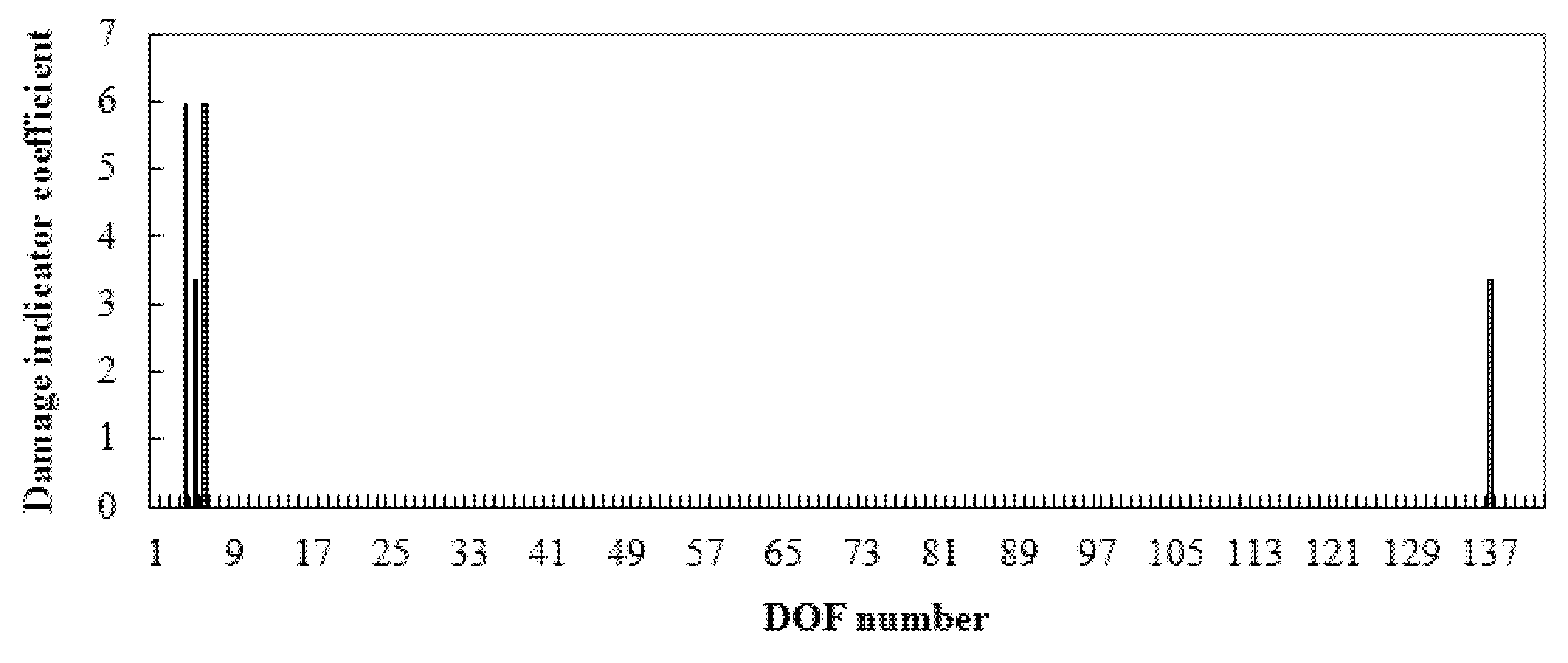
| 1 | α31 = 0.15 | α31 = 0.1518 | α31 = 0.15 |
| 2 | α15 = 0.15 | α15 = 0.1518 | α15 = 0.15 |
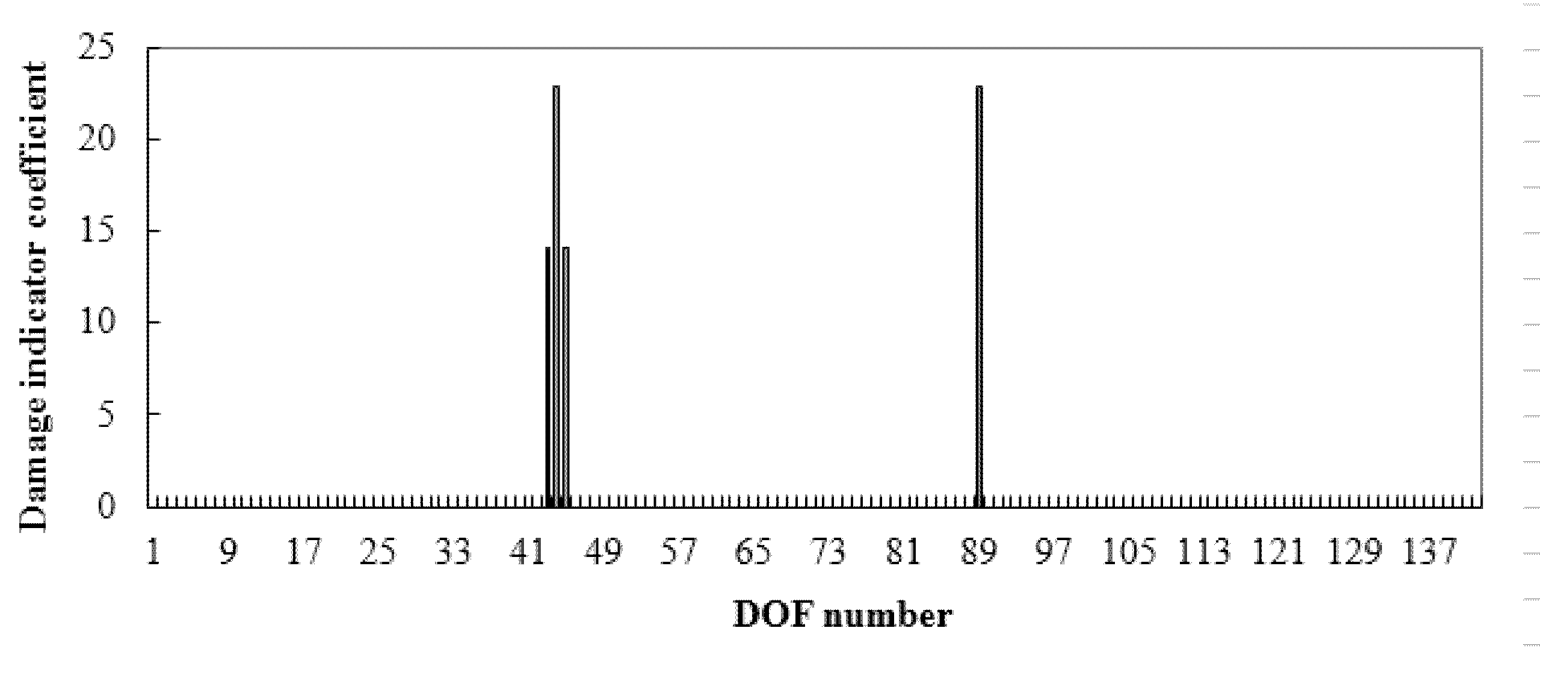
| 3 | α10 = 0.2 and α30 = 0.2 | α10 = 0.2033 and α30 = 0.2023 | α10 = 0.2 and α30 = 0.2 |
Publisher’s Note: MDPI stays neutral with regard to jurisdictional claims in published maps and institutional affiliations. |
© 2022 by the authors. Licensee MDPI, Basel, Switzerland. This article is an open access article distributed under the terms and conditions of the Creative Commons Attribution (CC BY) license (https://creativecommons.org/licenses/by/4.0/).
Share and Cite
Fang, R.; Wu, Y.; Wei, W.; Na, L.; Biao, Q.; Jiang, P.; Yang, Q. An Improved Static Residual Force Algorithm and Its Application in Cable Damage Identification for Cable-Stayed Bridges. Appl. Sci. 2022, 12, 2945. https://doi.org/10.3390/app12062945
Fang R, Wu Y, Wei W, Na L, Biao Q, Jiang P, Yang Q. An Improved Static Residual Force Algorithm and Its Application in Cable Damage Identification for Cable-Stayed Bridges. Applied Sciences. 2022; 12(6):2945. https://doi.org/10.3390/app12062945
Chicago/Turabian StyleFang, Rui, Yanting Wu, Wang Wei, Li Na, Qian Biao, Ping Jiang, and Qiuwei Yang. 2022. "An Improved Static Residual Force Algorithm and Its Application in Cable Damage Identification for Cable-Stayed Bridges" Applied Sciences 12, no. 6: 2945. https://doi.org/10.3390/app12062945
APA StyleFang, R., Wu, Y., Wei, W., Na, L., Biao, Q., Jiang, P., & Yang, Q. (2022). An Improved Static Residual Force Algorithm and Its Application in Cable Damage Identification for Cable-Stayed Bridges. Applied Sciences, 12(6), 2945. https://doi.org/10.3390/app12062945