Abstract
Acoustic micromembranes (AμMs) are attracting more and more attention due to their unparalleled light weight but high sound transmission loss (STL) at low frequencies. Previous works showed that AμMs feature remarkable sound insulation compared to homogeneous plates with the same surface mass density, while some follow-up works claimed that the outstanding insulation capability of small AμMs samples disappears when the sample size grows. To uncover the working mechanisms underpinning the unique behavior of AμMs, in this paper, we present theoretical and numerical studies of AμMs that couple the vibrations of the supporting frame and the AμMs within the lattice. The results show how the global response in the STL of the AμMs assembly is related to the geometrical parameters of AμMs cells and the lattice. This study provides a theoretical foundation for designing a large-scale yet high-insulation assembly of AμMs, and paves the way for applying AμMs for blocking low-frequency noise.
1. Introduction
Acoustic metamaterials (AMMs), as a family of macroscopic artificial composites, typically consist of many subwavelength-scaled structures arranged in a specific pattern so that they produce an optimized combination, not available in nature, of two or more responses to acoustic excitation [1]. In recent years, many acousticians have shown great interest in studying acoustic metamaterials [1,2,3,4,5] and have uncovered many new phenomena different from those associated with traditional acoustic materials [6,7,8,9,10,11,12,13].
Acoustic metamaterials have shown attractive features in noise control engineering. In 2015, Sui et al. performed experiments on the transmission loss (TL) of metamaterials arranged in a honeycomb frame [14] and showed that a significant TL could be achieved at low frequencies if the membrane was only 0.2 mm thick. We call such membrane-based metamaterials acoustic micromembranes (AμMs). Fellows further investigated Sui et al.’s approach, and found a way to optimize the TL in a honeycomb AMM [15,16]. In our recent work [17], we showed that the remarkable sound insulation at low frequencies rose from the high equivalent stiffness of the whole composite. When AμMs’ thickness is doubled, it provides an additional 18 dB of TL compared to traditional materials. When the size of an AμM is doubled, the TL decreases by 12 dB.
Although AμMs have very good TL at low frequencies and are lightweight, they are inapplicable when extending to large sizes [18]. Although efforts have been taken to design large-scale metamaterials, the low-frequency TLs have not been satisfactory [19,20,21]. To solve this problem, in this study, we theoretically investigated an array of square AμMs mounted within a lattice frame. If the frames are made hard enough to provide an approximately rigid boundary for every AμM cell, the TL of the whole assembly can be regarded as the same as that of a single cell. However, in practice, the frames are often somehow compliant, and it is thus difficult to demarcate rigidly each cell of the AμMs. In this work, by coupling the vibration of the frame and the AμMs within the lattice, we show how the global response of the TL of the AμMs assembly is related to the number of AμM cells and to the dimensions of the lattice.
2. Basic Calculation of a Square Membrane and Its Cross-Frame
Figure 1a shows the geometry of the AμM array and its frames, which are investigated in this paper. The structure is composed of a regular array of square holes in a solid material that is covered by a rubber membrane. The flexible membrane is clamped at the edges of the square holes, and the frame divides the whole membrane into a large number of AμMs. Each cell of the membrane, i.e., each AμM, has side length and thickness . Each cell of the lattice has width and thickness . In this work, the membrane is assumed to be made of latex rubber with a Young’s modulus , mass density , and Poisson’s ratio ; the frame is made of acrylic with Young’s modulus , mass density , and Poisson’s ratio .
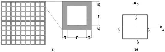
Figure 1.
(a) Structure of the AμMs. Each AμM is a small square held within a larger lattice frame. Each AμM has length r and thickness t; each cell of the lattice has width a and thickness . (b) Coordinate of an AμM cell used for calculating vibration.
As shown in Figure 1a, the investigated AμM was a 2D acoustic metasurface aiming at blocking low-frequency waves propagating in the out-of-plane direction. Although it is similar to a 2D crystal with a lattice parameter of (r + a), the presented work is not a study of photonic crystals. Studies on phononic crystals investigate in-plane waves that propagate along the crystal’s surface, in which wave–matter interaction (for example, Bragg reflections) occurs when the operating wavelengths are comparable with the lattice constant. In contrast, the AμMs here are used as a barrier for blocking incoming waves, in which the interaction of the metasurface with the out-of-plane waves are considered, and the lattice constant is much smaller than the operating wavelength.
The first step is to calculate the local response of each AμM cell. In this work, the membrane is made of latex rubber, and the size of an AμM is so small that it can be considered a thin plate when performing the calculation [22]. The reason for treating the AμM as a thin plate is because the membranes in each cell are rather small compared to the wavelength of the operating frequency. Such an assumption of thin plate approximation was adopted and verified in our previous work [17]. Assuming a thin plate is vibrating at a low frequency, the effective stiffness and effective mass of a AμM can be obtained. For each AμM, the vibration amplitude can be written as [17,23,24]:
where is the vibration amplitude of the AμM at position ; is Young’s modulus; is Poisson’s ratio; and are the density and thickness of the AμM, respectively; and is the pressure on the AμM (for incident sound pressure , then [17]. The coordinate system is shown in Figure 1b. The average vibration amplitude can be calculated by integration. Equating the kinetic energy calculated by lumping parameters and the sum of the energy in each infinitesimal part of the AμM, the equivalent stiffness and mass of a vibrating AμM can be written, respectively, as [17]:
Now that the local response of each AμM with rigid boundaries has been obtained, the next step is to calculate the vibration of the frame. The frame holds the whole membrane and consists of horizontal and vertical beams, where n is assigned as shown in Figure 2. To calculate the vibration of this arrangement of beams, a load distribution method is introduced. The idea is to separate the force into horizontal (x-direction) and vertical (y-direction) components. To calculate how the force is shared in different directions, we suppose that the vertical force is unknown, and then solve the problem by obtaining the balancing force required to produce equal displacement in each direction. Basically, this method, treating the supporting frame of AμMs as a grille, is a common approach in the force analysis of a grillage beam. The uniform load on the grille’s beams is equivalent to the sum of the loads at the cross-points, while the loads at the cross-points can be further decomposed into its x- and y-direction components. Interested readers can find details of this method in Ref. [25]. Here, the horizontal forces are designated , , …, , as shown in Figure 2. For the point in Figure 2, we obtain [25]:
where and are the matrices describing the displacement of a horizontal and a vertical beam under unit load, respectively; and are the vectors describing load distribution in the horizontal and vertical directions, respectively; and is a vector representing the force acting on each cross-point. Notice that this adopted method is valid below the first resonant frequency of the supporting frame. Since our investigated AμMs for noise insulation effectively work in the low-frequency range, it lies in the valid range of the method presented here. In this paper, all the forces acting on a point are the same and can be written as . Then, by solving the set of equations, the value of the unit force acting horizontally can be obtained.
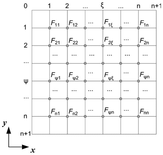
Figure 2.
The forces acting on each cross-point of the frame. The assignment of symbols follows the numbering scheme shown.
The displacement of every cross-point caused by a horizontal force can be obtained by the following equations
where the meanings of the variables are assigned as shown in Figure 3. In Equation (5), is the force acting on a cross-point of the beam, is the point to be calculated, is the distance of the force from one side of the boundary, is the length of the beam, is the Young’s modulus of the frame, and is the inertia moment of the beam, for which . For a certain cross-point , the displacement can be obtained by adding all the calculated from the horizontal-acting forces on every cross-point.
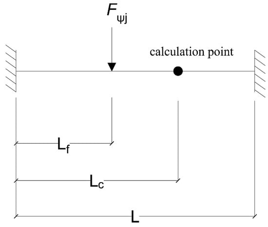
Figure 3.
Horizontal force acting on a beam of length L. and are, respectively, the distance of the force and the calculation point from the left side of the beam.
The entire assembly of AμMs provides two paths for sound transmission: via the AμMs and via the frame. Most of the works so far have considered the contribution from the AμMs [14,15,16,17]. However, for large-size AμM assemblies [18], the contribution from the frame cannot be ignored, and a lumped parameter method can be applied here since, in this low-frequency range, the lattice constant of the frame is much smaller than the operating wavelength. For the supporting frame, the displacements of each of the cross-points can be calculated by Equations (4) and (5), and can be written as . Then, the average displacement can be written as
Based on Equation (6), the stiffness of the frame can be further derived as
Similar to Equation (3), the effect of the mass of the frame can be calculated as
where is the density of the frame material and is its mass.
3. Response of the Supporting Frame
As shown in Figure 1, the whole membrane can be regarded as being composed of a large number of independent AμMs within the frame. When the vibration of the frame is small, it does not affect the AμMs much; hence, the response of the whole assembly is given by Equations (2) and (3). This means that the TL of the whole assembly will be no different from that of a single AμM, which holds for the case of a small assembly. However, when the assembly is larger, the vibration of the lattice frame can no longer be ignored and, in this case, the boundary of any two nearby AμMs cannot be regarded as rigid. So, now it is the case of a membrane mounted on a compliant frame, in which the effective stiffness and effective mass need to be calculated.
First, the displacement of the cross-points of the supporting frame can be obtained according to Section 2. Then, the averaged displacement of each AμM cell can be approximately evaluated as the sum of the displacement of an AμM given by Equation (1) (local response) and the averaged displacement of the four cross-points of the surrounding frame. With the number of AμMs assigned by their corner coordinates (top left corner) as shown in Figure 2, the displacement of the AμM, numbered , can be obtained as:
where is the average displacement of the AμM with rigid boundaries, is the displacement of the frame at cross-point , and is the average displacement surrounding the AμM numbered . In the calculation, the square of the force should be used, so that should be based on and should be based on , where is the unit force acting on the component. In general, the effective stiffness can be written as the force divided by the average displacement as
Then, the effective mass can be obtained by calculating its kinetic energy as
Up to this point, the equivalent stiffness and mass of each AμM mounted in a real (compliant) frame are derived. The entire assembly consists of all AμMs and the supporting frame. The transmission coefficient of sound energy (in STL) can be calculated by considering both the transmission path through the membrane cells (AμMs) and the supporting frame. Therefore, the sound pressure over the two transmission paths can be written as for the frame and for the AμMs, which are calculated, respectively, as follows:
where is the incident sound pressure, , , , , , and is the specific acoustic impedance of the frame and AμMs. and denote the area of the frame and of each AμM, respectively, so that and . Ra is the characteristic impedance of air, so , where and are the density and sound velocity of air, respectively. represents the sound pressure of each AμM transmission path and can be written in terms of the position of the AμM . The transmission coefficient for sound pressure can be expressed as and . The total sound power transmission coefficient and sound transmission loss TL can be eventually obtained as:
So far, the sound insulation property (in TL) of an array of AμMs mounted in a lattice has been obtained.
4. Global Response of the Assembly (AμMs Mounted within a Vibrating Frame)
In Section 3, the theoretical performance (in TL) of an array of AμMs was derived. To test the accuracy of the theory, a finite element simulation software package, COMSOL Multiphysics®, was adopted, and the assembly was simulated using the acoustic-shell interaction module in the frequency domain. Figure 4a shows the numerical model of the AμMs in COMSOL, where the AμMs assembly is mounted in a square-section tube and blocking the acoustic waves propagating bottom-up. The generated meshes of the AμMs shown in Figure 4b had dimensions smaller than one-sixth of the shortest wavelength (corresponding to frequency of 2000 Hz). In the simulation, both upper and lower sides of the assembly were occupied by air, and the air adjoined perfectly matched layers (PMLs), which allowed the sound to travel outward without causing any reflection. On the lower side of the assembly, a background sound field was created to investigate the sound insulation properties as measured by the sound field generated on the other side.
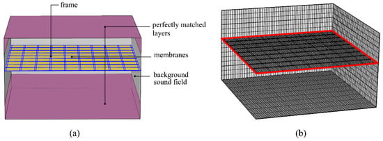
Figure 4.
(a) The COMSOL simulation model with perfectly matched layers (PMLs) on each side of the AμM assembly. A sound field was created on the lower side. (b) The model grid showing the fixed constraint set by the frame (red line).
5. Results and Discussions
Given the practical arrangement of a partition (or a barrier) for which insulation is required, the aim of this study was to prevent low-frequency sound transmission through a fixed-size hole by inserting the partition (which here refers to the AμMs assembly). An important factor is how the frame affects the sound insulation provided by the AμMs. Here, we theoretically and numerically calculated the TL of a fixed-size AμM assembly with different number of cells and the dimensions of the lattice. Figure 5 and Table 1, show how a partition for a square hole can be successively divided into smaller parts. Here, the frequency range of interest ranged from 10 to 1000 Hz for estimating the low-frequency acoustic behavior of the AμMs. In Figure 5a, the hole is composed of four AμMs (n = 1), each having a comparatively larger size ( mm). Such a large AμM cell is not stiff enough to provide sound insulation, and the TL curve quickly reverts to the mass law region. The hole was then divided into 16 parts, as shown in Figure 5b, i.e., n = 3, but the stiffness of the AμM was still too small. Sound insulation occurs mostly in the mass-control region. With the further increase in the cells in the frame, each AμM became stiff enough to bring the structure into the stiffness-controlled low-frequency region, as shown in Figure 5c for n = 7 and Figure 5d for n = 15. When the hole was divided into parts (n = 15), the TL of the structure could reach more than 30 dB at 100 Hz, which is in extreme contrast to the same hole divided into just a few parts shown in Figure 5a,b. We found that the theoretical predictions (black solid lines) agree well with the numerical ones (red dashed lines), especially at frequencies below the mass-control region. At higher frequencies, the deviation of theory from the numerical results comes from the AμM assembly vibrating in more complex, higher modes, which is the limitation of the currently adopt theoretical model.
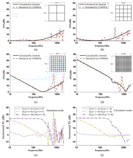
Figure 5.
Sound transmission loss in a hole as the number of AμM cells increases. Thickness of frame mm, width mm, edge length of the AμM mm, and thickness of the AμM mm. The number of AμM cells is (a), (b) , (c) , and (d) . (e) Incremental TL (simulation result) when the number of AμM cells in a column is doubled. (f) Incremental TL (calculation result) when the number of AμM cells in a column is doubled.

Table 1.
Displacements and resonant frequencies of the assembly when a 10 × 10 cm hole is successively divided into smaller parts.
Figure 5e,f shows by simulation and calculation, respectively, how TL increases when the number of AμM cells is doubled both in columns and rows. It can be seen that TL increases by about 22 dB at 10 Hz, when increases from three to seven (i.e., the number of AμMs in a column increases from four to eight), but the increases become smaller as the frequency increases. When further increases from 7 to 15, it provides an additional TL of about 24 dB over a relatively broad band of low frequencies. This result suggests that the strategy is efficient for noise control at low frequencies.
As indicated in Figure 5, a structure can be successively divided into more and more parts so that, eventually, the hole could be made up of a plate made only of the frame material. What would its TL be then? At that point, the TL would be high, but the weight of the component should also be taken into consideration. Notably, as aforementioned, our theoretical model considering the coupling of the membrane cells (AμMs) and supporting frame is valid below the first resonant frequency of the frame, which is the big dip in the STL curves in Figure 5b–d. So far, our theoretical model does not consider those higher modes of the supporting frame, which correspond to those quickly changing sharp peaks and dips of STL curves at higher frequencies (numerical results). Therefore, it is only meaningful by comparing the theoretical and numerical results below the fundamental resonant frequency of the frame. In this low-frequency range, the theoretical predictions agree well with the numerical results. Moreover, we observed that at higher frequencies, the theoretical results still show reasonable predictions of the general trend of the STL curves compared to numerical ones, except those sharp peaks and dips.
Figure 6 shows another case comparison, which is the STL of a thin acrylic plate and of a membrane–acrylic structure (AμMs) of the same weight. For a more practical use, the solid plate is now 20 × 20 cm in size and 2 mm in thickness. Then, the hole is divided into 400 parts (20 × 20 cells): the thickness of the frame is now 8.7 mm, the membrane thickness is 0.4 mm, the edge of each square is 8.95 mm, and the width of the frame is 1 mm. The total weights of the two arrangements are kept the same. When using the membrane–frame structure (i.e., the AμM assembly), the STL at a low frequency is around 8.6 dB higher, as suggested by the simulated result, while the calculated result is around 7.1 dB. The difference between the simulated and calculated results is caused by errors in the TL calculation for a single acrylic plate. In this work, the modeling of each membrane cell (AμM) is based on the thin plate approximation (i.e., shell model). This model usually holds when the plate thickness is an order of magnitude smaller than its side length. However, in this case, the plate thickness is 2 mm while its side length is 8.95 mm. Therefore, errors mainly come from the thin plate treatment for this extreme case. However, both methods indicate considerable advantages in terms of low-frequency insulation by using AμMs.
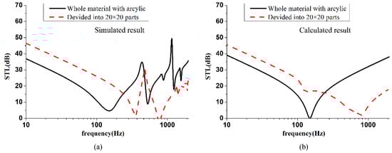
Figure 6.
(a) The simulated and (b) the calculated Sound transmission loss of a 20 × 20 cm hole filled with an acrylic plate of 2 mm thick (solid line) and of an AμM assembly (400 AμM cells supported by an acrylic frame) (red dashed line). The weights of the two structures are the same (the acrylic frame in the second case is 8.7 mm thick and the AμM 0.4 mm thick).
6. Conclusions
A theoretical model for calculating the transmission loss through an array of AμMs mounted in a lattice frame was presented. To be exact, the model shows how the frame affects the vibration and insulation properties of acoustic metamaterials (AμMs) at low frequencies. In designing such an array, estimating the resonant frequency and displacement of the frame is important but difficult. Both thickening and narrowing the frame can reduce its vibration and improve the transmission loss of the entire structure. Sui et al. [14] put forward a lattice-like frame, but the thickness of the frame was 25 mm, which produced a limiting case because the frame was rigid. By comparison, our work is more realistic, using a much thinner frame that is compliant and interacts with the motion of the AμMs.
Our results showed (Section 3) that both the frame and the AμMs affect each other’s acoustic behavior. When the vibration of the frame is stronger than that of the AμMs, increasing the stiffness of the AμMs can produce an extremely high TL of the assembly, and vice versa. For the most common case, when the vibration of the frame is much smaller than that of the AμMs, increasing the stiffness of the AμMs can produce an extremely high STL of the assembly. On the other hand, when the vibration of the frame is strong (corresponding to a super-dense grille-type frame dividing the whole membrane into a large number of ultra-small AμMs), increasing the stiffness of the frame will be the first priority. Moreover, if the vibration displacements of the AμMs and the frame are about equal, increasing the stiffness of either will have little effect on the TL of the whole assembly. We found that it is important to calculate the vibration amplitude of both the frame and the AμMs. Assuming that the aim of the study is to maximize the TL at low frequencies, our approach describes how to match the AμMs and the frame so that the target TL can be efficiently achieved.
In conclusion, AμMs have many advantages for low-frequency sound insulation. The governing principle is to ensure that the frame is strong enough to provide rigid boundaries for the AμMs, thereby ensuring that the insulation properties are controlled by the stiffness.
Author Contributions
Conceptualization, J.M. and X.W.; methodology, J.M.; software, J.M.; validation, J.M., Z.P. and X.W.; formal analysis, J.M.; investigation, J.M.; resources, J.M.; data curation, J.M.; writing—original draft preparation, J.M.; writing—review and editing, X.W.; supervision, X.W. All authors have read and agreed to the published version of the manuscript.
Funding
This research received no external funding.
Institutional Review Board Statement
Not applicable.
Informed Consent Statement
Not applicable.
Conflicts of Interest
The authors declare no conflict of interest.
References
- Fok, L.; Ambati, M.; Xiang, Z. Acoustic Metamaterials; Cambridge University Press: Cambridge, UK, 2008. [Google Scholar] [CrossRef]
- Liu, Z.; Chan, C.T.; Ping, S. Three-component elastic wave band-gap material. Phys. Rev. B 2002, 65, 165116. [Google Scholar] [CrossRef] [Green Version]
- Goffaux, C.; Sanchez-Dehesa, J.; Yeyati, A.; Lambin, P.; Khelif, A.; Vasseur, J.O.; Djafari-Rouhani, B. Evidence of Fano-Like Interference Phenomena in Locally Resonant Materials. Phys. Rev. Lett. 2002, 88, 225502. [Google Scholar] [CrossRef] [Green Version]
- Hirsekorn, M. Small-size sonic crystals with strong attenuation bands in the audible frequency range. Appl. Phys. Lett. 2004, 84, 3364–3366. [Google Scholar] [CrossRef]
- Liu, Z.; Zhang, X.; Mao, Y.; Zhu, Y.; Yang, Z.; Chan, C.T.; Sheng, P. Locally Resonant Sonic Materials. Science 2000, 289, 1734–1736. [Google Scholar] [CrossRef] [PubMed]
- Yang, Z.; Mei, J.; Yang, M.; Chan, N.H.; Sheng, P. Membrane-Type Acoustic Metamaterial with Negative Dynamic Mass. Phys. Rev. Lett. 2008, 101, 204301. [Google Scholar] [CrossRef] [PubMed]
- Naify, C.J.; Chang, C.-M.; McKnight, G.; Nutt, S. Transmission loss of membrane-type acoustic metamaterials with coaxial ring masses. J. Appl. Phys. 2011, 110, 751. [Google Scholar] [CrossRef] [Green Version]
- Naify, C.J.; Chang, C.-M.; McKnight, G.P.; Scheulen, F.; Nutt, S.R. Membrane-type metamaterials: Transmission loss of multi-celled arrays. J. Appl. Phys. 2011, 109, 104902. [Google Scholar] [CrossRef] [Green Version]
- Zhang, Y.; Wen, J.; Xiao, Y.; Wen, X.; Wang, J. Theoretical investigation of the sound attenuation of membrane-type acoustic metamaterials. Phys. Lett. A 2012, 376, 1489–1494. [Google Scholar] [CrossRef]
- Chen, Y.; Huang, G.; Zhou, X.; Hu, G.; Sun, C.-T. Analytical coupled vibroacoustic modeling of membrane-type acoustic metamaterials: Membrane model. J. Acoust. Soc. Am. 2014, 136, 969–979. [Google Scholar] [CrossRef] [Green Version]
- Xiao, S.; Ma, G.; Li, Y.; Yang, Z.; Sheng, P. Active control of membrane-type acoustic metamaterial by electric field. Appl. Phys. Lett. 2015, 106, 091904. [Google Scholar] [CrossRef] [Green Version]
- Blevins, M.G.; Lau, S.-K.; Wang, L.M. An impedance-mobility model of stacked membrane-type acoustic metamaterials. J. Acoust. Soc. Am. 2015, 137, 2298. [Google Scholar] [CrossRef]
- Lee, S.H.; Park, C.M.; Seo, Y.M.; Wang, Z.G.; Kim, C.K. Acoustic metamaterial with negative density. Phys. Lett. A 2009, 373, 4464–4469. [Google Scholar] [CrossRef]
- Sui, N.; Yan, X.; Huang, T.-Y.; Xu, J.; Yuan, F.-G.; Jing, Y. A lightweight yet sound-proof honeycomb acoustic metamaterial. Appl. Phys. Lett. 2015, 106, 171905. [Google Scholar] [CrossRef]
- Lu, K.; Wu, J.H.; Guan, D.; Gao, N.; Jing, L. A lightweight low-frequency sound insulation membrane-type acoustic metamaterial. AIP Adv. 2016, 6, 025116. [Google Scholar] [CrossRef] [Green Version]
- Yang, Y.; Li, B.; Chen, Z.; Sui, N.; Chen, Z.; Saeed, M.-U.; Li, Y.; Fu, R.; Wu, C.; Jing, Y. Acoustic properties of glass fiber assembly-filled honeycomb sandwich panels. Compos. Part B Eng. 2016, 96, 281–286. [Google Scholar] [CrossRef]
- Li, S.; Mao, D.; Huang, S.; Wang, X. Enhanced transmission loss in acoustic materials with micro-membranes. Appl. Acoust. 2018, 130, 92–98. [Google Scholar] [CrossRef]
- Peiffer, A.; Grünewald, M.; Lempereur, P. Comment on “A lightweight yet sound-proof honeycomb acoustic metamaterial” [Appl. Phys. Lett. 106, 171905 (2015)]. Appl. Phys. Lett. 2015, 107, 216101. [Google Scholar] [CrossRef] [Green Version]
- Ang, L.Y.L.; Koh, Y.K.; Lee, H.P. Broadband sound transmission loss of a large-scale membrane-type acoustic metamaterial for low-frequency noise control. Appl. Phys. Lett. 2017, 111, 041903. [Google Scholar] [CrossRef]
- Varanasi, S.; Bolton, J.S.; Siegmund, T. Experiments on the low frequency barrier characteristics of cellular metamaterial panels in a diffuse sound field. J. Acoust. Soc. Am. 2017, 141, 602–610. [Google Scholar] [CrossRef] [Green Version]
- Marinova, P.; Lippert, S.; Von Estorff, O. On the numerical investigation of sound transmission through double-walled structures with membrane-type acoustic metamaterials. J. Acoust. Soc. Am. 2017, 142, 2400. [Google Scholar] [CrossRef]
- Morse, P.M. Vibration and Sound; McGraw-Hill: New York, NY, USA, 1948. [Google Scholar]
- Xu, Z. Applied Elasticity; Higher Education Press: Beijing, China, 1992. [Google Scholar]
- Liu, X.; Cui, X.; Wang, S. Comparison for solving method of rectangular thin plate deflection under uniform load. Sichuan Arch. 2008, 28, 99–100. [Google Scholar]
- Bao, F. Calculation Handbook of Cross-Beam Structure under Static Force; China Architecture & Building Press: Beijing, China, 1989. [Google Scholar]
Publisher’s Note: MDPI stays neutral with regard to jurisdictional claims in published maps and institutional affiliations. |
© 2022 by the authors. Licensee MDPI, Basel, Switzerland. This article is an open access article distributed under the terms and conditions of the Creative Commons Attribution (CC BY) license (https://creativecommons.org/licenses/by/4.0/).