1. Introduction
Recently, information and communication technologies have seen tremendous growth, and with the increased use of high-speed internet, video conferencing, live streaming, and other services, bandwidth and capacity requirements are increasing [
1]. This ever-increasing demand for data and multimedia services has caused congestion in the conventionally used radio frequency (RF) spectrum, requiring a shift from RF carriers to optical carriers [
1]. While the use of RF spectrum is restricted, optical carriers do not require spectrum licensing, making them an attractive prospect for high-bandwidth, high-capacity applications [
2]. Free-space optical (FSO) communications make use of laser beam propagation as the signal carrier, allowing wireless communications between transmit-and-receive optical terminals. By modulating data in low-divergence laser beams, the optical carrier’s beam spread is much narrower than that of an RF carrier. This causes an increase in signal intensity at the receiver for a given to transmit power [
3]. Other benefits of FSO communications include easy expandability and reduced sizes of network segments, being lightweight and compact, and being useful where fiber optic cables cannot be used.
FSO technology is being developed for short- and long-distance terrestrial links, satellite uplink/downlink, inter-satellite links, deep-space probes to ground, and ground–air/air–ground applications. Among them, satellite–ground communication research is the most relevant these days for both industry and academia. With the advent of space-borne scientific equipment, numerous spacecraft can gather considerable volumes of data to be downloaded to a ground station [
4]. However, due to limitations on the number and duration of periods in which a spacecraft is above the local horizon and available for line-of-sight (LOS) communications with a given ground station, as well as onboard memory storage on the spacecraft, RF systems are falling short of meeting the increasing demand from spacecraft to transmit information to a ground station at high speed. To this end, laser communications can be a viable option because it provides a higher data rate than traditional RF systems. In addition, satellite–ground laser communications play a major role in 5G and beyond-5G technologies because they can extend a coverage area providing data services not coverable by terrestrial cellular networks and enabling data delivery to the edge of a network. Project Loon and Project Aquila are good examples of FSO communications used in real-world settings. Project Loon, a subsidiary of Alphabet’s X, floats a balloon up to 20 km (12 miles) above the ground to deliver Internet service to rural areas [
5]. Project Aquila is another emerging FSO project—a solar-powered drone developed by Facebook for use as an atmospheric satellite, serving as a relay station to provide internet access to remote areas [
5].
In satellite–ground communications, to establish an accurate LOS link between the ground station and the satellite, an uplink beacon is utilized for precise acquisition and tracking. Once the signal is received, the controller logic on the satellite turns the onboard laser on for the downlink. When the downlink beam is picked up by the ground station, transmission from the onboard laser can take place. For both uplink and downlink applications, the laser beam travels through the atmosphere in which significant factors such as cloud, snow, fog, and rain can severely impact (and even terminate) the link. These factors have variable properties and cause attenuation and degradation of the received signal due to photon absorption and scattering [
6]. Moreover, the beam suffers from atmospheric turbulence, which is a random phenomenon caused by temperature and pressure variations in the atmosphere along the propagation path. The turbulence in the atmosphere causes intensity fluctuations in the received signal, which is known as scintillation. The scintillation index is determined by the refractive index structure parameter, denoted as C
2n. The strength of turbulence in the atmosphere is determined by this parameter. C
2n varies depending on several factors, including geographic location, weather conditions, and time of day [
7,
8,
9].
In satellite–ground FSO scenarios, there is a big difference between uplink and downlink, which is caused by completely different link geometry. Regarding uplink, turbulence is only present in the very short slice at the beginning of the path. No turbulence will interfere with the propagation of the signal beyond the top layers of the atmosphere. Because the beam is distorted early in its route through the atmosphere before propagating in free space, the effect of scintillation on uplink is more severe than on downlink. On downlink, the laser beam covers the first 99% of the total distance without interruption. The transmitter’s wavefront properties alone determine its divergence, and the turbulence is concentrated at the end of the propagation route [
10]. The scintillation index, the Fried parameter, and the Greenwood frequency (the reciprocal of coherence time) are the three key atmospheric-turbulence characteristics for any future satellite–ground link design because they significantly affect the link budget [
11].
Previous FSO communication studies widely explored FSO channel characteristics. Khalighi and Uysal [
12] addressed many FSO link concerns from the perspective of communication theory. They discussed various losses experienced in terrestrial FSO communications, information about FSO transceivers, channel coding, and modulation, as well as strategies to lessen the effects of air turbulence on fading. However, terrestrial FSO communications are the focus of most of their work. Liu et al. [
13] evaluated appropriate laser wavelength selection for FSO transmission considering atmospheric attenuation, including absorption and scattering by molecules and aerosols. Gupta [
14] examined the impact of adverse weather on an FSO link and used cases for three optical transmission windows (850 nm, 1310 nm, and 1550 nm) of an FSO connection in the presence of attenuation caused by fog, snow, rain, and scattering. Furthermore, research was conducted on link budget analyses of free-space optical satellite networks showing appropriate system models for the links and to study link transmission power at different distances and at various elevation angles on uplink/downlink [
15]. Moll [
16] analyzed measurement data and the selection of theoretical models for LEO downlink scenarios. However, these conventional works still did not give readers a thorough analysis of the correlation between channel parameters such as coherence length, zenith angle, and the refractive index structure parameter for both uplink and downlink scenarios.
Therefore, in this paper, we examine the impacts of the atmosphere on FSO uplink and downlink communications, considering the correlation between channel parameters. Various atmospheric influences are considered by presenting mathematical equations for atmospheric factors such as fog attenuation coefficients, refractive index parameters, interference lengths, turbulence models, and variations in the angle of arrival. Unlike conventional FSO channel research, which was focused mostly on variations in atmospheric turbulence and changing the wavelength, we analyzed variations in atmospheric turbulence according to coherence length, zenith angle, and refractive index structure parameter. FSO uplink and downlink channels were investigated by simulating various channel conditions, and our experimental results show that using a 1550 nm wavelength is preferred to mitigate the effects of turbulence, while a larger receiver aperture reduces the angle of arrival fluctuation.
2. Uplink and Downlink Channels in Satellite–Ground FSO Communications
In uplink and downlink satellite–ground communications, the optical signal propagates through the Earth’s atmosphere and loses power due to a variety of factors such as the geographic environment, time of day, and weather. Environmental factors, such as clouds, snow, fog, rain, and haze, cause significant attenuation in the optical signal. Unlike radio communications, optical communications cannot pass through most types of cloud cover [
17]. In addition, atmospheric turbulence in the daytime is comparatively more than at night [
18]. The responsibility of an FSO system designer is to carefully examine the design requirements to minimize signal attenuation due to the atmosphere. Atmospheric attenuation factors in both satellite–ground and ground–satellite communications are discussed in this section.
2.1. Satellite−Ground FSO Channel Environments
Earth’s surface warms by absorbing solar radiation, causing the adjacent layer of air to warm as well [
18]. The warmer air rises above and turbulently mixes with the relatively cooler surrounding air, resulting in random temperature fluctuations. Turbulent inhomogeneities lead to the formation of turbulent cells, also known as eddies, of varying temperatures. These eddies behave like refractive prisms of varying sizes and refractive indices, interfering constructively or destructively with the propagating beam [
2,
18]. An optical beam spreads out due to diffraction when turbulent eddies are smaller than the transmitted beam. If turbulent eddies are significantly larger than the beam, it is deflected from its original path, causing it to wander and potentially miss the receiver. When a turbulent eddy’s size is the same as the transmitted beam, the received signal intensity fades randomly, resulting in beam scintillation [
2].
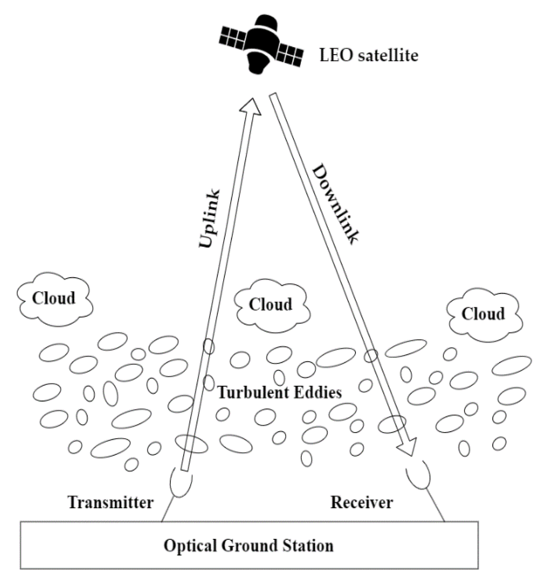
Figure 1 illustrates the effect of turbulent eddies on satellite–ground FSO communications on both uplink and downlink. We can see from
Figure 1 that the source of attenuation is closer to the transmitter on uplink. On downlink, the source of attenuation is closer to the receiver. Therefore, turbulent eddies of different diameters and refractive indices affect the FSO channel differently for uplink and downlink, respectively.
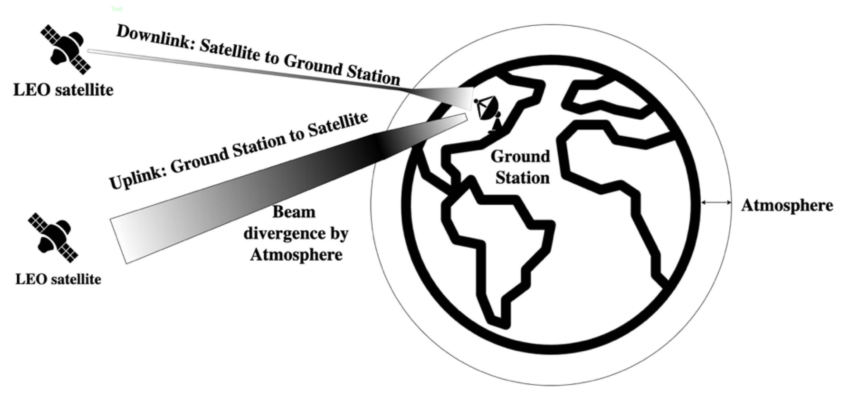
Figure 2 illustrates beam divergence caused by the atmospheric channel for both uplink and downlink FSO channels. As shown in
Figure 2, the optical beam starts to spread and acquires distortion the moment the optical signal is emitted from the ground station during uplink. However, on downlink, the optical signal passes through free space for much of the propagation path and is only disrupted by atmospheric turbulence for a short distance. Hence, optical signal attenuation due to the atmosphere on ground–satellite uplink is comparatively more than on satellite–ground downlink.
In FSO link design, system designers should have a full understanding of beam propagation via random atmospheric conditions and the related losses in order to establish a reliable FSO communication link between the transmitter and the corresponding receiver. As mentioned earlier, due to the presence of turbulent eddies of varying temperatures, sizes, and refraction indices in the atmosphere, a series of turbulence effects is produced when the optical wave propagates through the atmosphere. Hence, the optical beam suffers a variety of losses when traveling through the atmospheric optical channel. In the following subsections, these losses are discussed.
2.2. Absorption and Scattering Loss
Laser beams traveling through the Earth’s atmosphere may interact with molecules in the atmosphere along their paths. As a result of the interaction, light photons are absorbed when the quantum state of a molecule is excited to a higher energy level, extinguishing some of the photons and converting their energy into heat [
18]. At visible and infrared wavelengths, water, carbon dioxide, and ozone molecules act as the primary atmospheric absorbers. The biggest concentration of these atmospheric absorbers is often found between one and two kilometers above the Earth’s surface [
18].
The phenomena of absorption due to atmospheric absorbers depend on the wavelength [
18]. Based on this, the FSO communications system’s wavelength range is chosen for the least amount of absorption. The range of wavelengths having the least amount of absorption is known as the atmospheric transmission window. Several transmission windows exist in the near-infrared wavelength range of 700 to 1600 nanometers for FSO communications systems [
2]. Transmitter and detector components in this wavelength range are easily available on the market since they are also used in fiber optic communications. Hence, this paper focuses on the 700–1600-nanometer near-infrared wavelength range to observe channel characteristics of satellite−ground FSO communications.
Infrared and visible electromagnetic waves scatter when they travel through air molecules and other airborne particles. Scattering of light also results in the deterioration of FSO system performance. Scattering introduces noise into the FSO communication system by scattering sky radiance into the receiver. Like absorption, light scattering is wavelength-dependent. Rayleigh scattering is caused by air molecules and haze that are minuscule in comparison to the radiation’s wavelength. Particles with the same size as the radiation’s wavelength cause Mie scattering [
2]. Rayleigh scattering is greatly influenced by air molecules and haze. Mie scattering is caused by fog and haze [
2].
The combined effect of absorption and scattering is frequently calculated using extinction, which is defined as the reduction or attenuation of the amount of energy passing through the atmosphere. On the other hand, atmospheric transmittance refers to the ability of the atmosphere to transmit radiation. It is the ratio of transmitted radiation to total incident radiation in the atmosphere. The relation between atmospheric attenuation and atmospheric transmittance (T
atm) is described by Beer’s law [
19], which is given by
where γ is the atmospheric attenuation coefficient, H is the vertical height of the atmospheric channel, λ is the operating wavelength, and θ is the zenith angle. The atmospheric attenuation coefficient γ depends on the integrated distribution of atmospheric constituents along the propagating path [
18] in addition to the operating wavelength.
Fog is one of the most frequent types of atmospheric attenuation because the constituent particle sizes are comparable in size to the laser’s wavelength inducing absorption and scattering [
19]. To predict attenuation, it is essential to understand the size and water content of the fog particles. However, it is challenging to find this information because it is frequently not accessible at the FSO link installation site. Researchers, as a result, have produced empirical models based on visibility data gathered from city meteorological stations. Using common empirical models, visibility information can be used to calculate attenuation due to fog. According to the Kruse model [
18], atmospheric attenuation coefficient β
λ due to fog can be described in terms of meteorological visibility V (in kilometers) and transmittance threshold (T
th) as follows:
where λ
0 is the maximum spectrum of the solar band and δ is given by
The most popular T
th values are 2% and 5% [
18]. A popular empirical model for calculating the attenuation coefficient is the Kim model [
18]. The Kruse model’s coefficient can be changed in accordance with Kim’s theory as follows:
2.3. Atmospheric Turbulence
The diurnal cycle and the varying rates at which sunlight heats and cools the Earth cause significant variations in air temperature. The refractive index of air fluctuates arbitrarily as a result of random temperature changes, creating turbulence in Earth’s atmosphere [
20]. Turbulent cells, also known as eddies, will form as a result of turbulence and will vary in size and refractive index [
18]. The distortion brought on by this phenomenon affects how light travels through the atmosphere. Consequently, a laser beam suffers distortions on a satellite-ground FSO link. Beam spreading (beyond that caused by pure diffraction), random changes in the location of the beam centroid (beam wander), and random redistribution of beam energy within a cross-section of the beam (irradiance fluctuations) are all effects of wavefront distortions in the optical wave caused by atmospheric turbulence [
7].
When the magnitude of turbulence eddies exceeds the size of the beam, the phenomenon known as beam wander occurs. The beam will be randomly deflected from its propagation route, which causes link failure. On uplink, the transmitted laser beam is distorted by atmospheric turbulence near the transmitter, and hence, the laser beam, for a long period of propagation, suffers from free space diffraction. Therefore, along with scintillations, beam wander is a major concern for the uplink channel [
7]. When the size of the eddies is less than the size of the beam, beam spreading is taken into consideration. In this scenario, the incoming beam will be separately diffracted and scattered, causing the received wavefront to be distorted [
2]. The atmospheric turbulence close to the ground interferes with satellite–ground laser communications, but for most of the path, the beam largely travels over free space. As a result, the beam is quite broad when it encounters the atmospheric layer. Hence, scintillations and angle-of-arrival variations are the main issues with downlink propagation channels [
7].
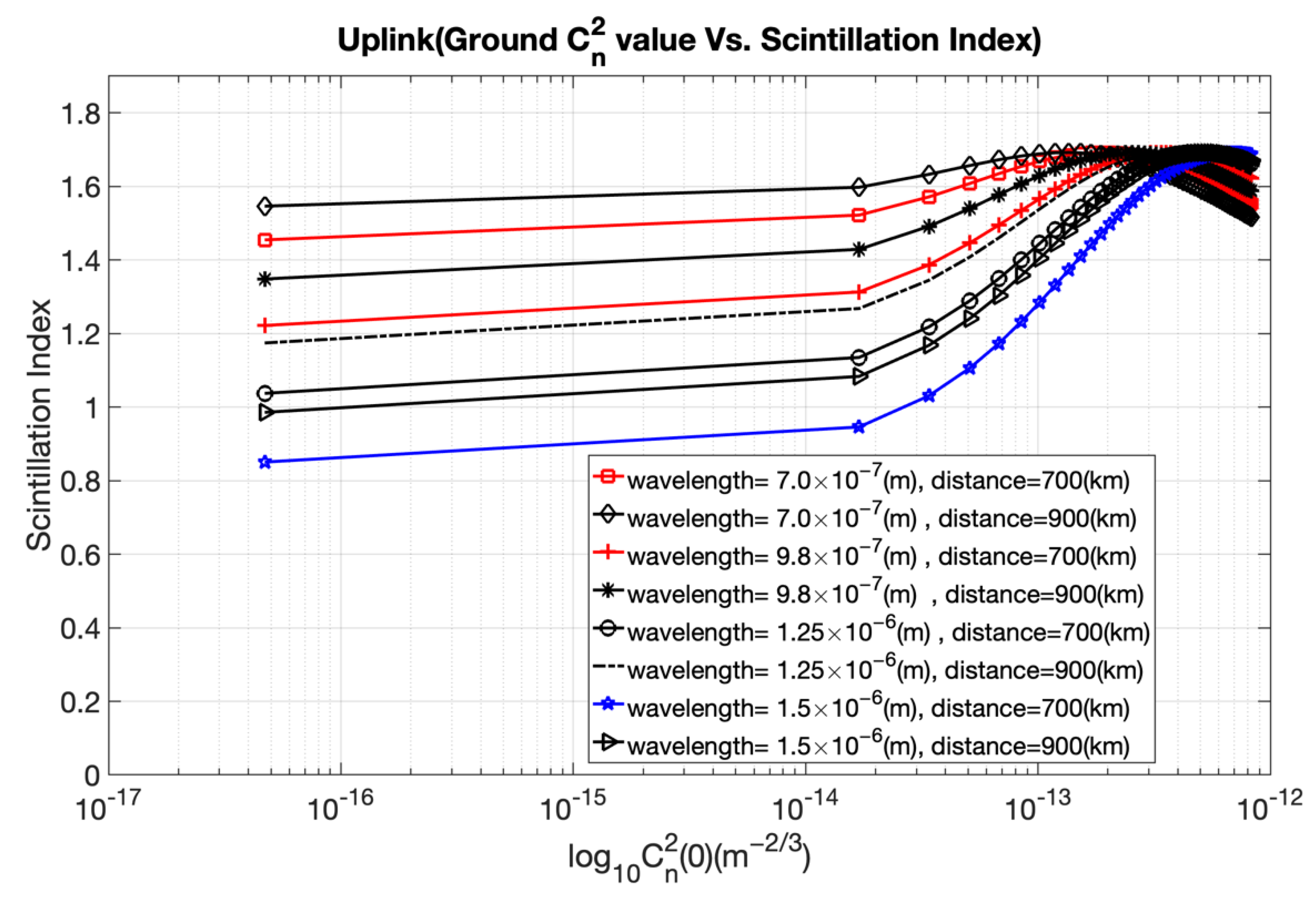
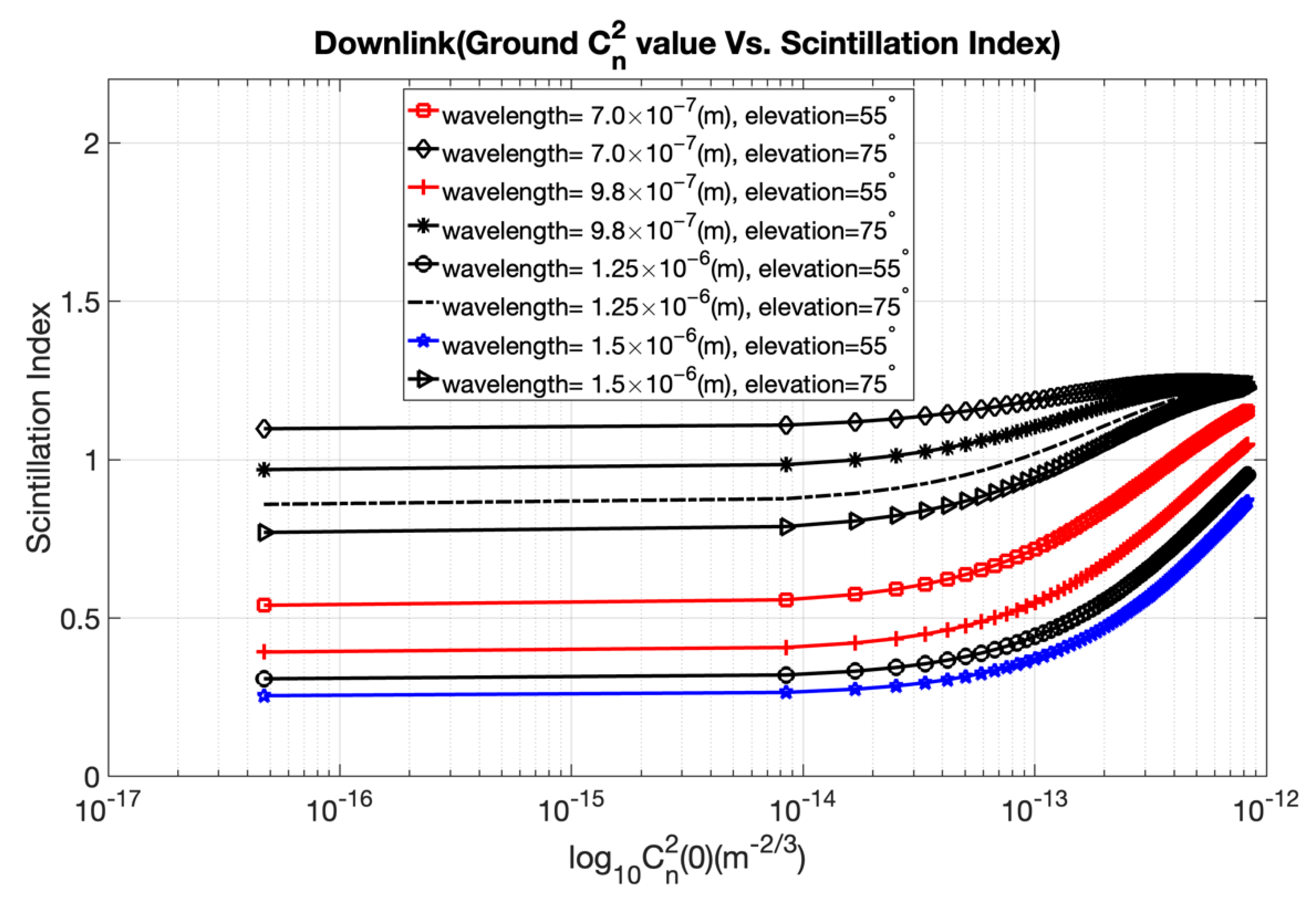
The scintillation index, which is a function of the refractive index structure parameter, is used to measure atmospheric scintillation. The refractive index structure parameter, denoted as C
n2 and developed by Kolmogorov, is an essential parameter for measuring the level of refractive index variation in atmospheric turbulence [
18]. The refractive index structure is constant for horizontal paths but should be considered to vary throughout the propagation path for vertical links. The Hufnagel Valley model is a heuristic model that uses the refractive index parameter to characterize turbulence conditions. The model predicts that the refractive index structure parameter at altitude h can be expressed as follows [
1]:
where h is the height above sea level in meters, A is the nominal value of C
n2(0) at the ground in m
−2/3 and v
wind is the rms wind speed in meters per second. Equation (5) clearly shows that the refractive index structure parameter depends on wind speed and altitude above sea level, which depend upon the spatial location of the receiver and the time of day. Hence, the spatial location of the receiver and the time of day play a vital role in the system design of FSO links for satellite–ground and ground–satellite channels.
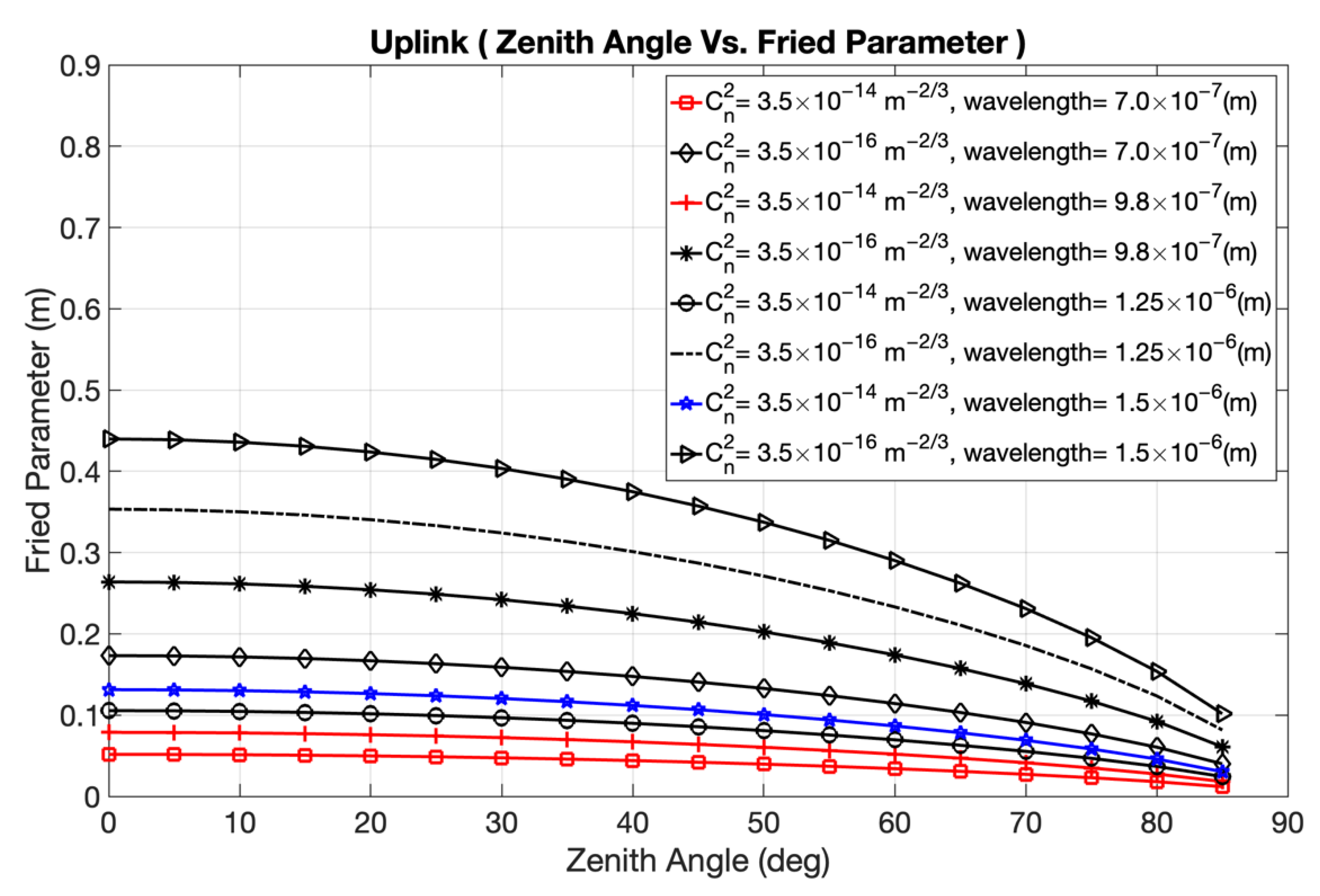
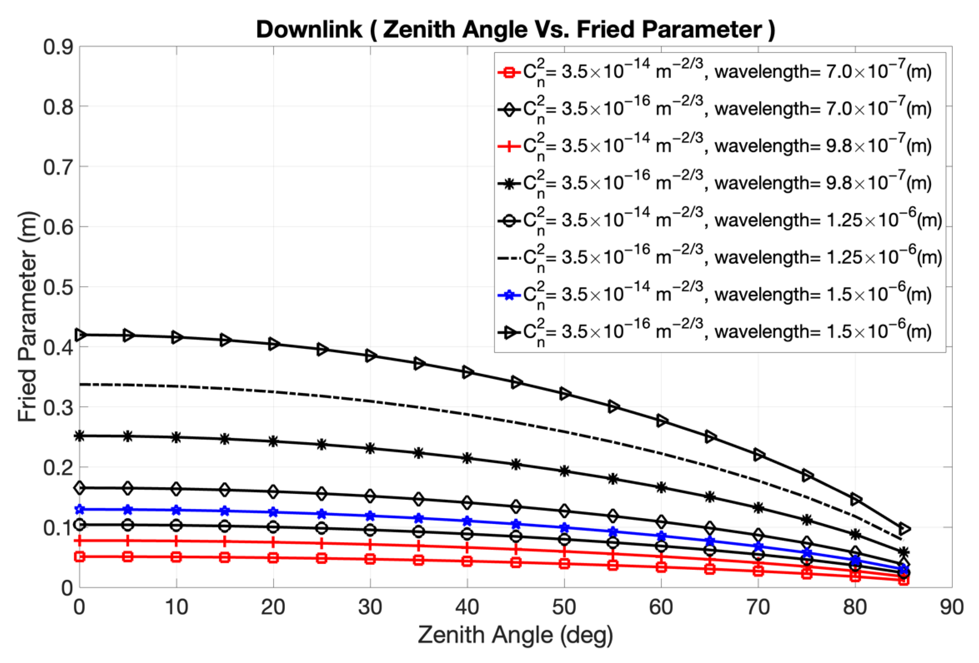
An essential FSO channel parameter that depends on Cn2 is the atmosphere’s coherence length. Coherence length describes the spatial coherence characteristic of a light wave moving in an unsteady environment. The coherence length is typically in the 5 cm to 30 cm range.
For a plane wave(downlink), the coherence length is given as explained in [
19]:
For a spherical wave(uplink), the coherence length is given as explained in [
21]:
where θ is the zenith angle, k is the wave number, h
0 is the altitude of the ground station, and H is the satellite altitude. For FSO system designers, one of the main considerations when choosing an optical wavelength for transmission in an FSO system is atmospheric attenuation because the choice of wavelength determines the amount of optical signal attenuation due to the atmosphere. FSO systems employing a 1550-nanometer wavelength may transmit more than 10 times as much optical power than the systems employing 750-nanometer or 850-nanometer wavelengths [
2]. From Equations (6) and (7), it is clear that coherence length depends on the wave number, which is inversely proportional to the operating wavelength. Hence, coherence length r
0 varies with λ
5/6. Therefore, a higher degree of coherence will be present in an FSO link operating at higher wavelengths than at lower wavelengths.
Another important factor in the design of FSO channels is the turbulence model for scintillation. The severity of intensity fluctuations in transmission across FSO networks has been examined using a variety of models. Gamma–Gamma distribution is widely used to model fading approximation.
For FSO channels with irradiance variations, the scintillation index using Gamma–Gamma distribution is given as follows [
2]:
For a plane wave (downlink channel), it is
For a spherical wave (uplink channel) [
22], it is
where θ is the zenith angle, k is the wave number, h
0 is the altitude of the ground station, L is the link distance, and σ
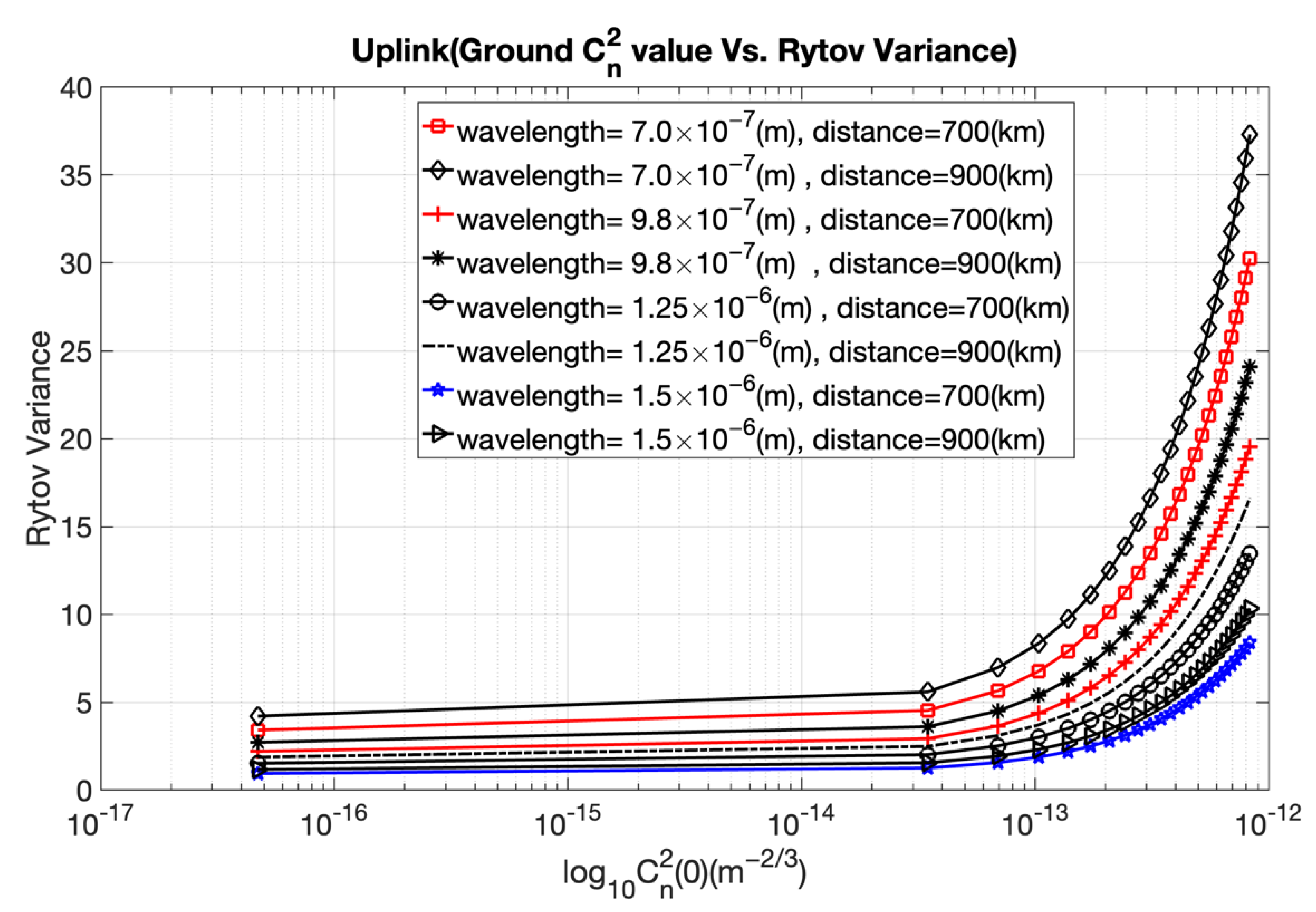
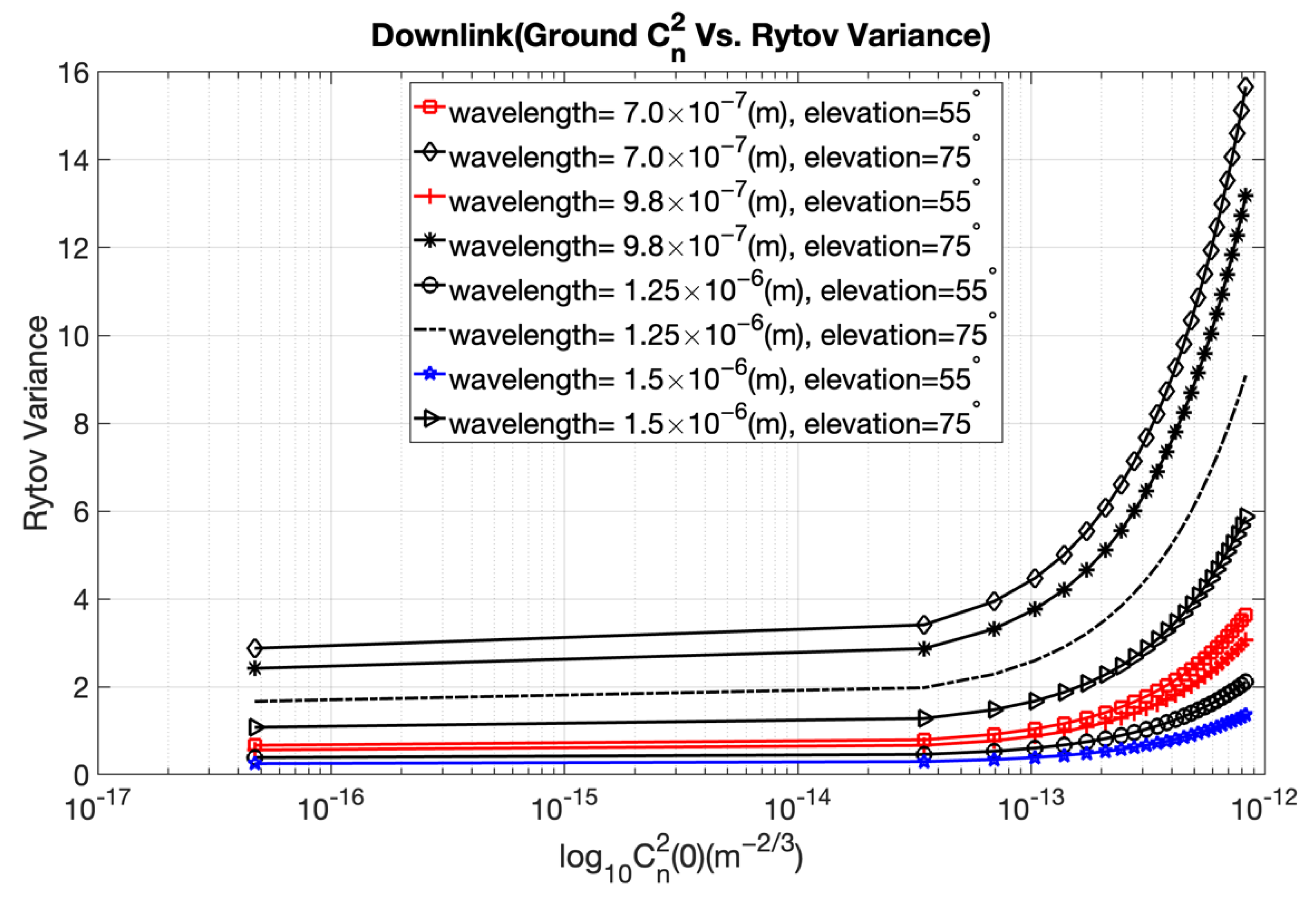
2I is the Rytov variance. The numbers of small- and large-scale eddies in the scattering environment are denoted by the parameters α and β, respectively. Large-scale and small-scale eddies will behave as a prism or a lens and will interact with a laser beam traveling through the atmosphere, forming constructive or destructive interference. Equations (11) and (14) depict how the Rytov variance depends on the refractive index structure parameter and wave number. Rytov variance and the scintillation index parameter determine the strength of intensity fluctuations. Optical signal attenuation caused by the atmosphere is significantly greater on ground−satellite uplink than on satellite−ground downlink. For uplink and downlink FSO channels, the wavelength and refractive index structural parameter should be taken into consideration in order to assess the strength of intensity fluctuations and to calculate the optimal value of Rytov variance and the scintillation index.
2.4. Angle-of-Arrival Fluctuations
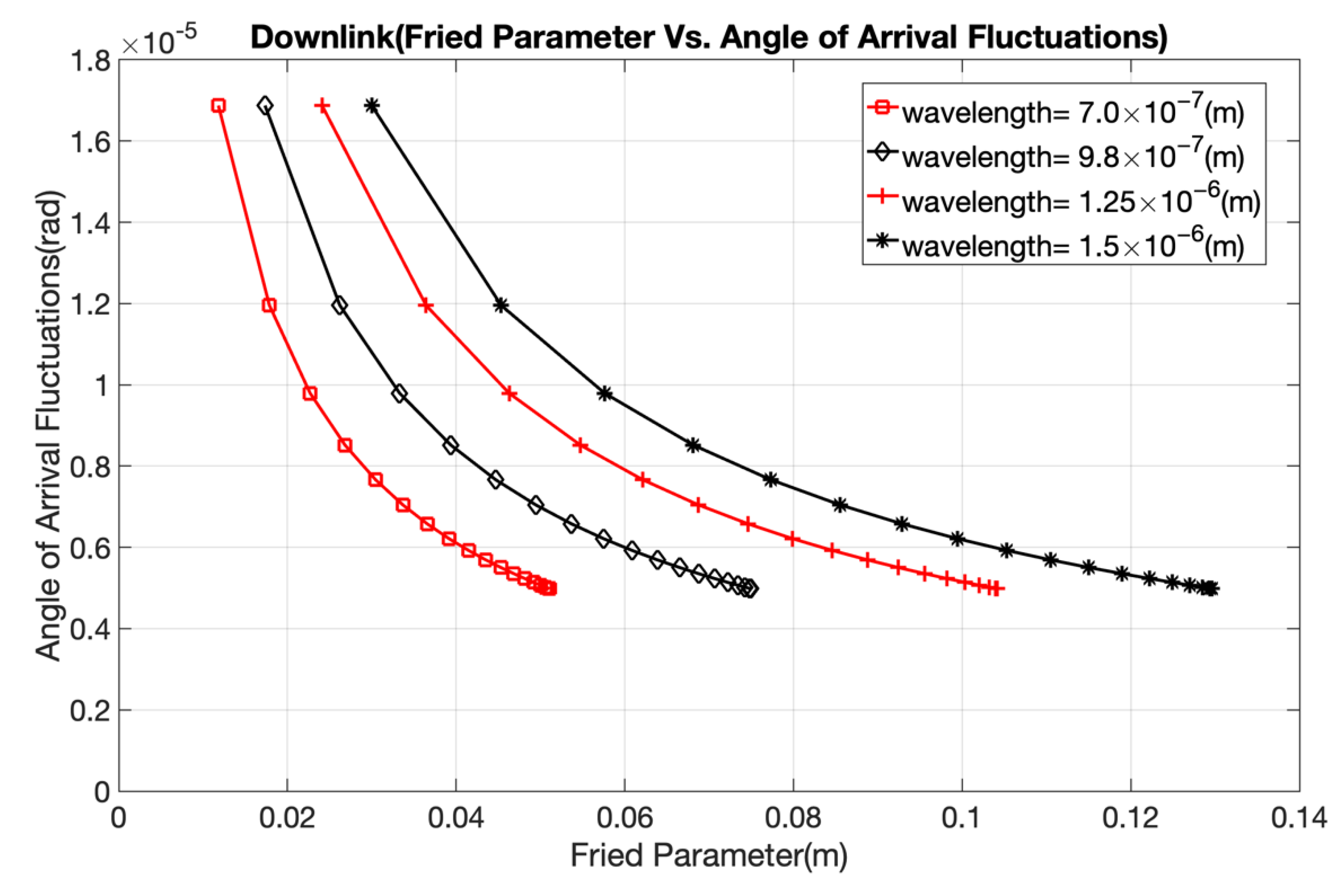
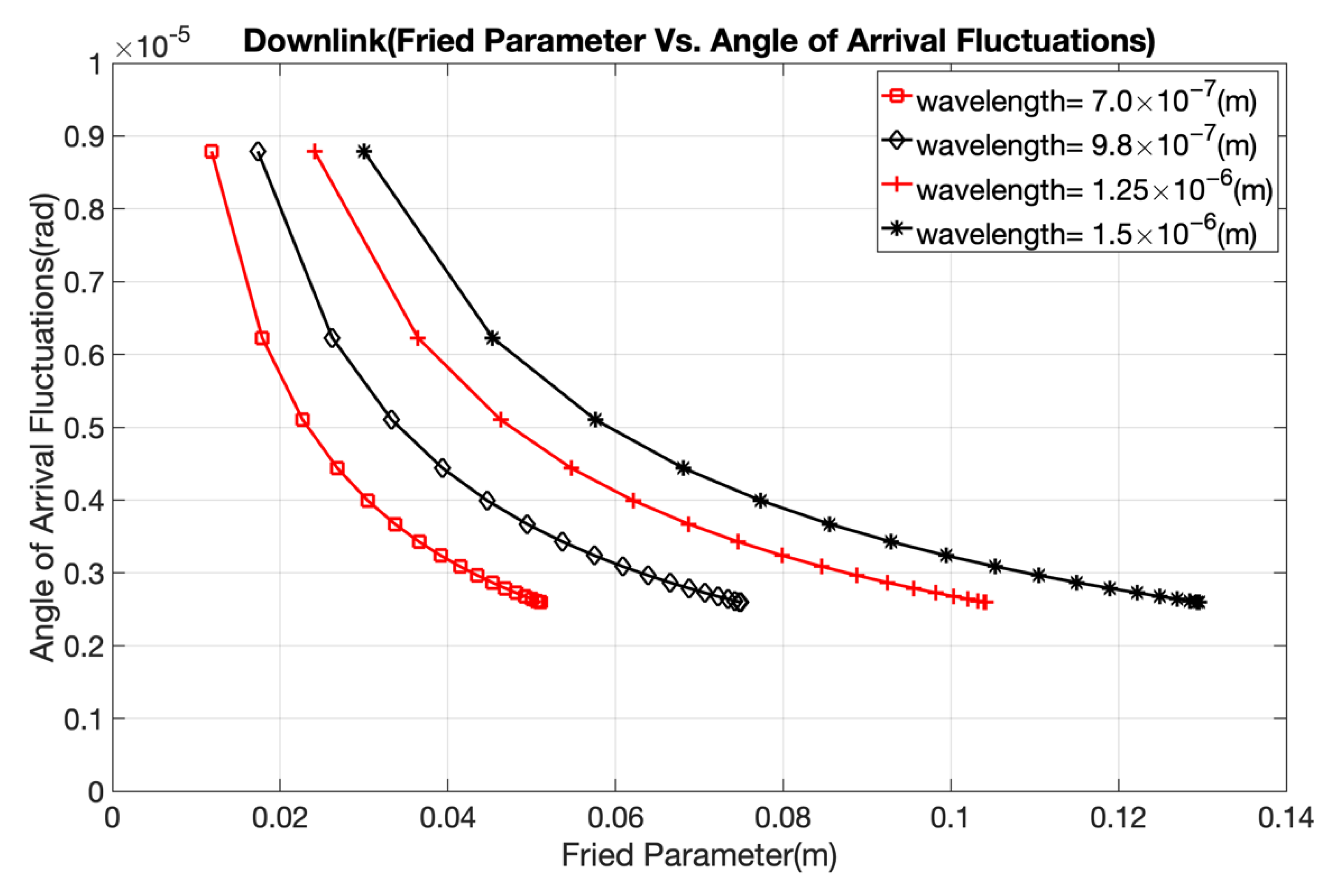
In FSO communications channels, the wavefront of a laser beam arriving at the receiver is distorted because of atmospheric turbulence. This phenomenon causes image motion in the focal plane, which is also known as angle-of-arrival fluctuation. For a plane wave, the angle-of-arrival fluctuation is given as follows [
2]:
The above equation is further simplified [
16]:
where D is the diameter of the receiver aperture and r
0 is the coherence length. The angle-of-arrival fluctuation leads to a loss of spatial coherence in the optical beam [
7]. Because of the loss of spatial coherence, laser beams can only be focused to a limited extent. This results in significant reductions in the power level of optical communication systems. When the size of the receiver aperture is increased, relatively fast fluctuations caused by small-sized eddies are averaged out. This helps reduce channel fading on a downlink FSO channel. Hence, the size of the receiver diameter should be considered when designing FSO channel links.
2.5. Channel Parameters
To find the optimal FSO system parameters needed for near-Earth uplink/downlink transmissions between a satellite and a ground station, we vary several parameters highly related to the FSO channel environment. For this, important FSO design parameters such as wavelengths, satellite altitude, ground station altitude, and ground station aperture diameter are varied to observe how the FSO channel behaves. In addition, we illustrate how the varied channel parameter impacts other related parameters in the FSO link. Based on the obtained result, we present the recommended channel parameter values needed for a near-Earth FSO system design. The values used in the simulation for ground station altitude, satellite altitude, ground station aperture diameter, and the wavelengths are listed in
Table 1. All the simulations are carried out in MATLAB R2022a (9.12) on a Windows 10 operating system.
4. Discussions and Conclusions
In this paper, we examined the impact of the atmosphere on FSO uplink/downlink channels between satellites and ground stations. We present mathematical equations on atmospheric factors such as fog attenuation coefficient, refractive index parameter, coherence length, turbulence model, and angle-of-arrival fluctuation to consider various atmospheric effects. Different channel conditions were simulated, and the effects on channel performance were investigated to aid in the design of FSO links.
By adjusting channel parameters, we illustrated the impacts of optical channel parameters and channel conditions on FSO channel performance. Our primary contributions of this paper are as follows.
We present the correlation between various distinctive parameters that impact the near-Earth FSO channel, such as coherence length (Fried parameter), zenith angle, refractive index structure parameter, scintillation index, Rytov variance, and angle-of-arrival fluctuations.
We confirm the appropriate wavelength to be considered while designing uplink and downlink satellite–ground communications in the presence of atmospheric turbulence. The 1550 nm wavelength is best suited for both uplink and downlink because atmospheric turbulence has less impact, and the coherence length is longer, compared to shorter wavelengths.
We suggest that the location and altitude of an optical ground station should help ensure a constant wind speed, and we demonstrate that the value of the refractive index parameter, which characterizes the strength of turbulence in the atmosphere, is less with increases in altitude above sea level.
Overall, our results provide a broad perspective on how a channel behaves and on what measures need to be taken to improve the communications system for FSO links. The findings of this study can be used to build satellite–ground FSO links and determine the best link parameter values.
