Abstract
For parallel hybrid electric vehicles (HEVs), the clutch serves as a vital enabling actuator element during mode transitions. The expected drivability and smoothness of parallel HEVs are difficult to be achieve owing to the neglect of clutch-torque-induced disturbance and different response characteristics of power sources during clutch slipping. To address this issue, this paper proposes a novel control strategy to coordinate the engine and motor during the clutch slipping process. A sliding mode control strategy based on a group-preserving scheme was applied to control the motor. The vehicle dynamic equation was constructed by the sliding surface with the Lagrange function. The equation solutions obtained by introducing the Runge–Kutta method were used as motor control inputs. Meanwhile, an adaptive PI controller was designed to regulate engine speed for the reduction in the speed difference of the clutch. The hardware-in-the-loop simulations were conducted to validate the outstanding performance of the proposal strategy. The verification results indicate that the proposed strategy not only reduces the vehicle jerk and frictional losses effectively, but also improves vehicle driving comfort and reliability.
1. Introduction
More severe environmental pollution and energy crisis problems are forcing the development of clean, efficient vehicles with low emissions. Hybrid electric vehicles (HEVs) with artistic multi-power-source designs possess the merits of high efficiency, a negligible driving range limitation and easy braking energy regeneration, representing a promising development direction in the automobile industry [1,2,3]. To reduce fuel consumption and emissions, HEVs can operate in a suitable mode for different traffic conditions [4,5,6,7]. However, the frequent mode transitions will lead to the deterioration in the performance of HEVs due to the clutch-torque-induced disturbance and differences in dynamic characteristics between the engine and motor. A noticeable jerk occurs especially during the clutch slipping process, which may shock the powertrain [8,9]. Hence, the quality of the mode transition should be considered when designing the control strategy for HEVs.
Recently, lots of control strategies have been investigated and presented that deal with the mode transition problem for HEVs. Koprubasi et al. presented a coordinated control strategy for parallel HEV based on hybrid control theory [10]. Hybrid controllers were designed for several switched hybrid dynamical systems, and results demonstrate that a seamless transition can be achieved using the proposed controllers. In [11], during mode transitions, the model reference control (MRC) method was applied in a series-parallel HEV to coordinate the clutch torque, motor torque and engine torque. Compared to the conventional method, the MRC method could reduce torque interruption and achieved less vehicle jerk. In [12], taking various unmodeled dynamics and parameter uncertainties into consideration, engine-side and motor-side controllers were devised separately by using feed-forward and robust feedback control strategies. The simulation results demonstrate that the drivability performance for a parallel HEV was improved significantly. Additionally, Kim et al. utilized disturbance observers to devise a four-phase control algorithm for parallel HEVs with a clutch during mode transitions [13]. Yang et al. proposed a hierarchical control system based on the robust H∞ control strategy to realize a smooth and fast mode transition for a plug-in HEV [14]. Based on the available research, it can be deduced that the essence of these control algorithms is the coordinated control for the engine and motor during mode transitions. The expected vehicle drivability and smoothness can be guaranteed by suppressing fluctuations in coupling torque on the driveshaft while satisfying the torque requirements of the vehicle [15]. However, the influence of clutch torque is not considered in the existing coordinated control strategies. The speed fluctuations on both sides of the clutch, as well as the variation in the friction coefficient with the temperature of the friction plate, will results in a significant nonlinear characteristic of the torque transferred by the clutch [16,17,18,19]. The torque ripple generated by the engine at the side of driving plate can also have an adverse effect during the process of clutch engagement. Despite the short duration of the slipping phase, the nonlinear variation in torque will intensify the mismatching torque in the vehicle powertrain, leading to an obvious unpleasant driving sensation [20,21,22,23]. Hence, further improvement in the drivability and smoothness of HEVs during mode transition remains a challenge.
Focusing on the mode transition process from the electric mode to the hybrid driving mode, this paper proposes a novel coordinated strategy to deal with deterioration issues in the drivability and smoothness for parallel HEVs. First, a novel sliding mode control (SMC) strategy based on the group-preserving (GP) scheme was devised to control the motor. The dynamic differential equations for the vehicle during the clutch slipping process were constructed using the sliding surface with the Lagrange function, and the solutions could be solved by using the Runge–Kutta method. Second, an adaptive PI control strategy was designed to adjust the engine speed to realize the trajectory tracking of the driven plate, in which the parameter of the PI controller was updated online by a fuzzy algorithm. Finally, hardware-in-the-loop (HIL) simulations were conducted to validate the effectiveness of the proposed strategy.
The paper is organized as follows: Following the Introduction, the vehicle dynamic model is described in Section 2. In Section 3, the SMC-GP strategy and adaptive PI controller are described, respectively. Next, we explain how the proposed coordinated control strategy was implemented in the HIL, and verification results are provided and described in Section 4. Finally, conclusions and future works following on from this study are presented in Section 5.
2. Parallel HEV System Model
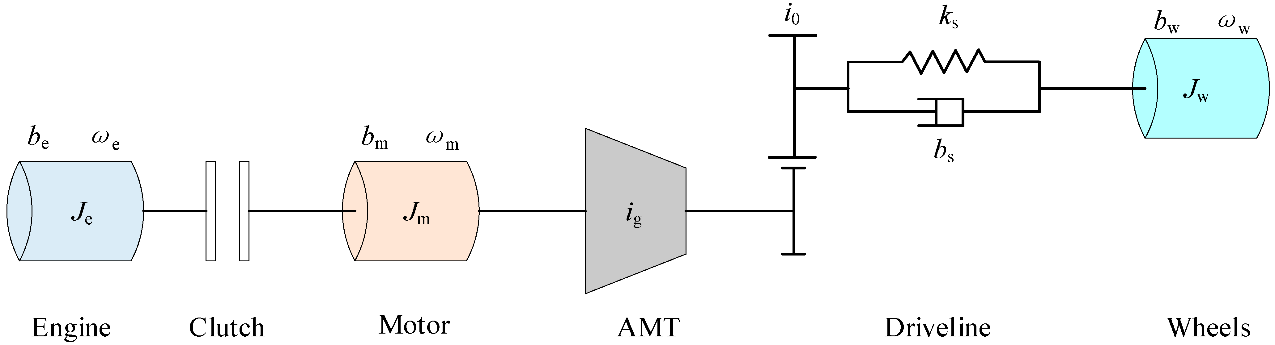
The simplified topology of the studied parallel HEV is shown in Figure 1. The engine, motor and automated mechanical transmission (AMT) are located on the same axis without the configuration of an extra coupling device. Such a layout provides greater reliability in a compact space. For dealing with different operating conditions, the clutch can be engaged or disengaged to enable the mode transition. In the electric drive mode, the clutch is open and only the motor provides the demanded torque to drive the vehicle [24,25]. In the hybrid drive mode, the engine drives the vehicle together with the motor, and the clutch is locked. Therefore, the clutch serves as a vital enabling actuator element for mode transitions of the parallel HEV. The specification of the main components of the studied parallel HEV is listed in Table 1.
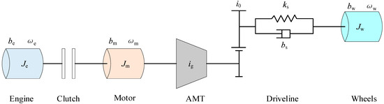
Figure 1.
Simplified topology of the HEV architecture.

Table 1.
The main parameters of the studied parallel HEV.
This study focused on the impact of both clutch-torque-induced disturbance and different dynamic characteristics between the engine and motor on the performance of the parallel HEV. Using the lumped parameter method [26], the differential equation for vehicle dynamic performance during the clutch slipping process can be depicted as:
where Je is the combined inertia of the engine and accessories, Jm is the combined inertia of the motor rotor and transmission on the motor side, and Jw is the inertia of the wheels. ωe, ωm and ωw are the engine speed, motor speed and wheel speed, respectively. bm is the motor internal friction coefficient, be is the engine friction coefficient, and bw is the damping coefficient of tires. ig and i0 are the gear ratios of the AMT and final drive, respectively. bs and ks are the equivalent damping coefficient and spring coefficient of the driveline, respectively. θs denotes the torsional displacement of the driveshaft. Te and Tm are the engine torque and motor torque, respectively. Tc and TL are the clutch torque and vehicle load torque, respectively. In addition, the vehicle load torque can be calculated by:
where g is the gravity acceleration, m is the gross mass, fr is the rolling resistance coefficient, θ is the road slope angle, A is the frontal area, CD is the air drag coefficient, va is the vehicle velocity, and δ is the modified coefficient of the rotating mass.
Additionally, the torque transferred from the clutch can be divided into three parts, which is closely related to the friction under the action of the normal force between the two sides of clutch [27,28,29]. The clutch torque is calculated by:
where Ti denotes the input torque of the driving plate, uc denotes the clutch friction coefficient, Nc denotes the friction plate number, Fc denotes the normal force, R denotes the outer radius of the diaphragm spring, r denotes the inside radius of the diaphragm spring, and △ω denotes the speed difference. Here, sgn() is the sign function expressed as the following mathematical formula.
According to Equation (3), the clutch torque exhibits strong nonlinear characteristics, especially in the slipping process, which has a prominent influence on the drivability and smoothness. Moreover, the different dynamic characteristics between the motor and engine will further cause the deterioration of driving comfort. In this paper, a coordinated control strategy was devised to improve drivability performance of parallel HEVs during the clutch slipping process.
3. Control Strategy Description
Comprehensively considering the energy conversion efficiency, a parallel HEV should be started in the electric mode [30]. The motor can provide the required torque to drive the vehicle, and the engine is shutdown in this situation. When the instantaneous velocity is greater than the preset threshold Ve_max, the mode transition from the electric mode to hybrid driving mode is triggered. The starting motor will start the engine at idle speed, and then the clutch is locked. When the driving plate rotates synchronously with the driven plate, the vehicle enters into the hybrid driving mode. On the contrary, when the instantaneous velocity is less than the preset threshold Ve_max, the vehicle will enter the electric mode. The diagram of the above-mentioned mode transition is shown in Figure 2.
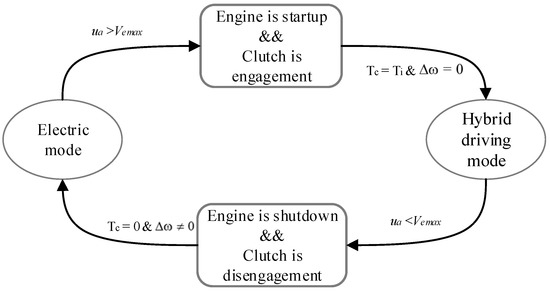
Figure 2.
The diagram of the mode transition.
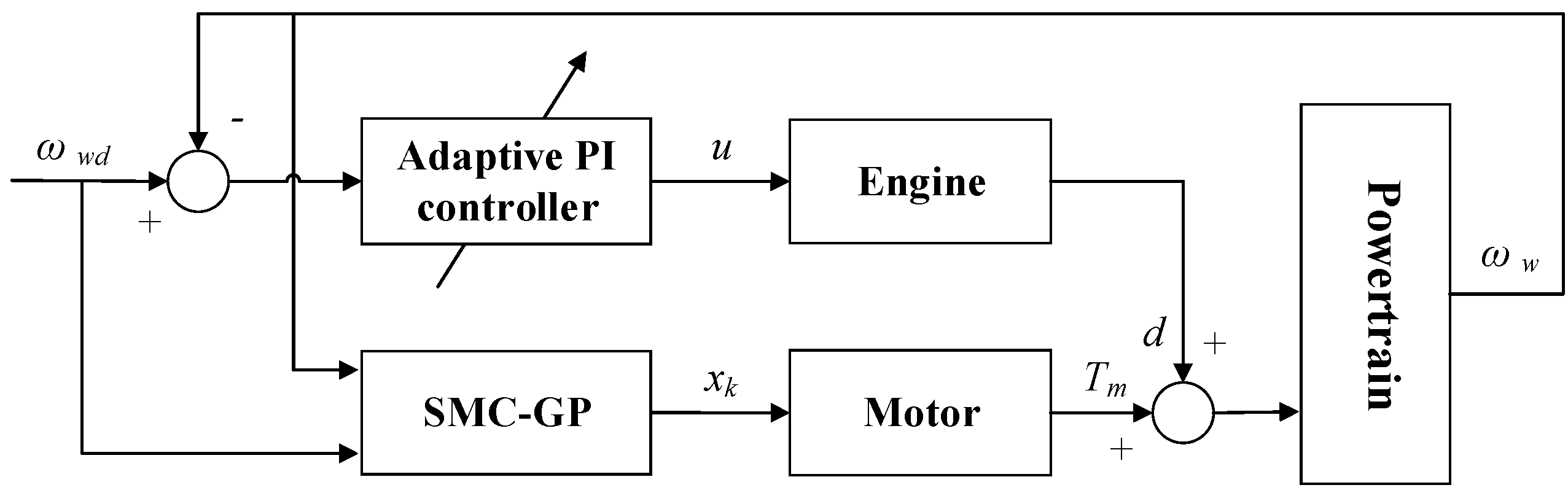
During the clutch slipping process, the disturbance torque is introduced to the HEV powertrain. If the output torque of the motor is still in accordance with the torque commands given by the energy management strategy (EMS), the torque demand of the driver may not be satisfied, which results in the deterioration of the drivability performance. Furthermore, the speed difference of the clutch may increase the torque disturbance. The driven plate speed is equal to the speed of the motor, which can be derived from the vehicle velocity. Then, the speed difference can be reduced by engine speed regulation. Considering the interaction between the two power sources during clutch slipping, the proposed coordinated control strategy, including an adaptive PI control strategy for engine control and an SMC-GP algorithm for motor control, is proposed in this research, as illustrated in Figure 3.
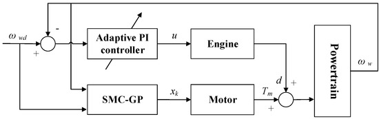
Figure 3.
Block diagram of proposed coordinated control strategy during clutch slipping.
3.1. Control Strategy for the Motor
For the studied parallel HEV, the motor is a key component that can be controlled to compensate for the disturbance torque during clutch slipping. In this situation, the motor, as the sole power supplier for the parallel HEV, must also be able to achieve accurate tracking of the target velocity. Here, we consider a general nonlinear system, as follows:
where x(t) stands for the system state, u(t) denotes the control input, and t0 and tf are the initial time and terminal time, respectively. For a given general performance function J(u), the control input u(t) should satisfy the following condition:
where F(x(tf), tf) is the terminal index function, and L(x, u, t) is the Lagrange function. U is the maximum of control input. Since the control input is independent of the Lagrange function, the above equation can be transformed into:
The appropriate Lagrange function with positive constants M0 and α can be defined by:
On the basis of this definition, we can further deduce and obtain the equation as follows.
According to Equations (6), (7) and (9), the following inequality can be derived by
That is, if the control input u(t) is derived from Equation (8) and satisfies corresponding constraints, a smaller performance index than that of Equation (10) can be obtained. Considering the complexity of the motor control problem during the clutch slipping process, an SMC strategy was selected to solve this problem.
3.1.1. SMC Strategy
In terms of control theory, SMC is a nonlinear control method with strong immunity and robustness for parameter perturbation and external disturbance, and does not rely on an accurate control system model [31]. The control input is changed for a certain purpose that can force the system trajectory to move on a predetermined sliding surface. As shown in Figure 4, the system trajectory will gradually converge to the sliding surface S(x) = 0. Therefore, the SMC strategy is suitable for application in the motor control during the clutch slipping process, as it can avoid the phenomenon of torque interruption and unfavorable drivability.
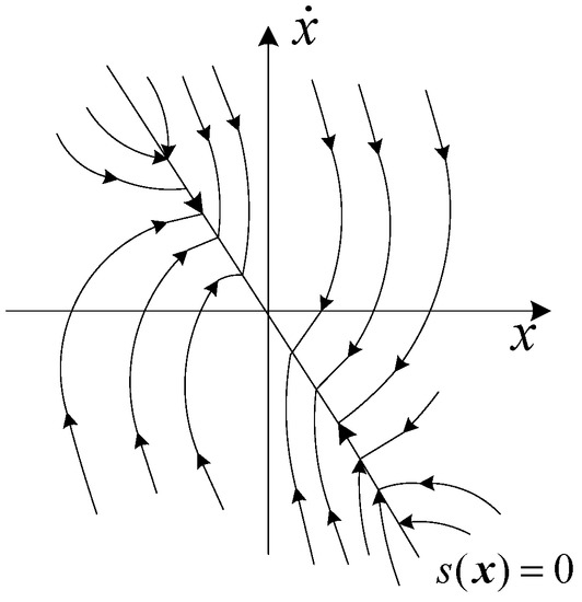
Figure 4.
The diagram of the sliding mode motion.
Here, the motor torque is selected as the control variable. The motor speed is regarded as the system state variable, and its ideal trajectory xd can be defined as:
where ωwd is the expected wheel speed, and its value is dependent on the vehicle velocity. From Equation (8), the sliding surface with the Lagrange function can be designed as:
where k denotes the constant with a positive value. When the system is in sliding mode, the equation will be satisfied. The control law u1 can be derived as follows:
where d is the disturbance, and it contains the modeling error and parameter perturbation; χ is a positive constant. When the state trajectory reaches the sliding mode surface, the system will traverse between both sides of the sliding surface and approach the equilibrium point. During this process, the control variable will generate high-frequency oscillation [32]. In this study, sgn(s) is replaced by the continuous function θ(s) to restrain the chattering phenomenon.
where σ is the positive constant with a smaller value.
xd = ωwd·ig·i0
S= k(x − xd) − L(x, t) = k(x-xd) − M0 exp(−αt)
3.1.2. GP-SMC Strategy
In 2001, the group-preserving scheme was first proposed by Liu [33]. The differential equations representing a nonlinear system can be converted into a Lie algebra in the augmented space of Minkowski. By using a group-preserving scheme with Cayley transformation and Padé approximation, the augmented state points can be updated to lie on the cone [34]. The asymptotic behavior of the original dynamic systems is preserved. In this way, spurious solutions and ghost fixed points can be easily excluded. The differential equations are solved using the Runge–Kutta method, which not only maintains the characteristics of the Hamilton function, but also guarantees an accuracy of O (h4), where h is the step size.
In general, the torque required by the vehicle is determined by the EMS in accordance with the driver’s intentions. For the proposed HEV powertrain, the vehicle velocity is related to the motor speed and can be expressed as:
where Rw is the wheel radius. The precise control of the motor helps to satisfy the driver’s driving intentions, especially during the clutch slipping process. Hence, the sliding mode control strategy based on the group-preserving (GP-SMC) scheme ensures that the motor can accurately accomplish a specific trajectory tracking. According to Equation (11), the differential equations concerning the vehicle dynamic during the clutch slipping process are reconstructed as:
where , Tm_max stands for the maximum motor torque.
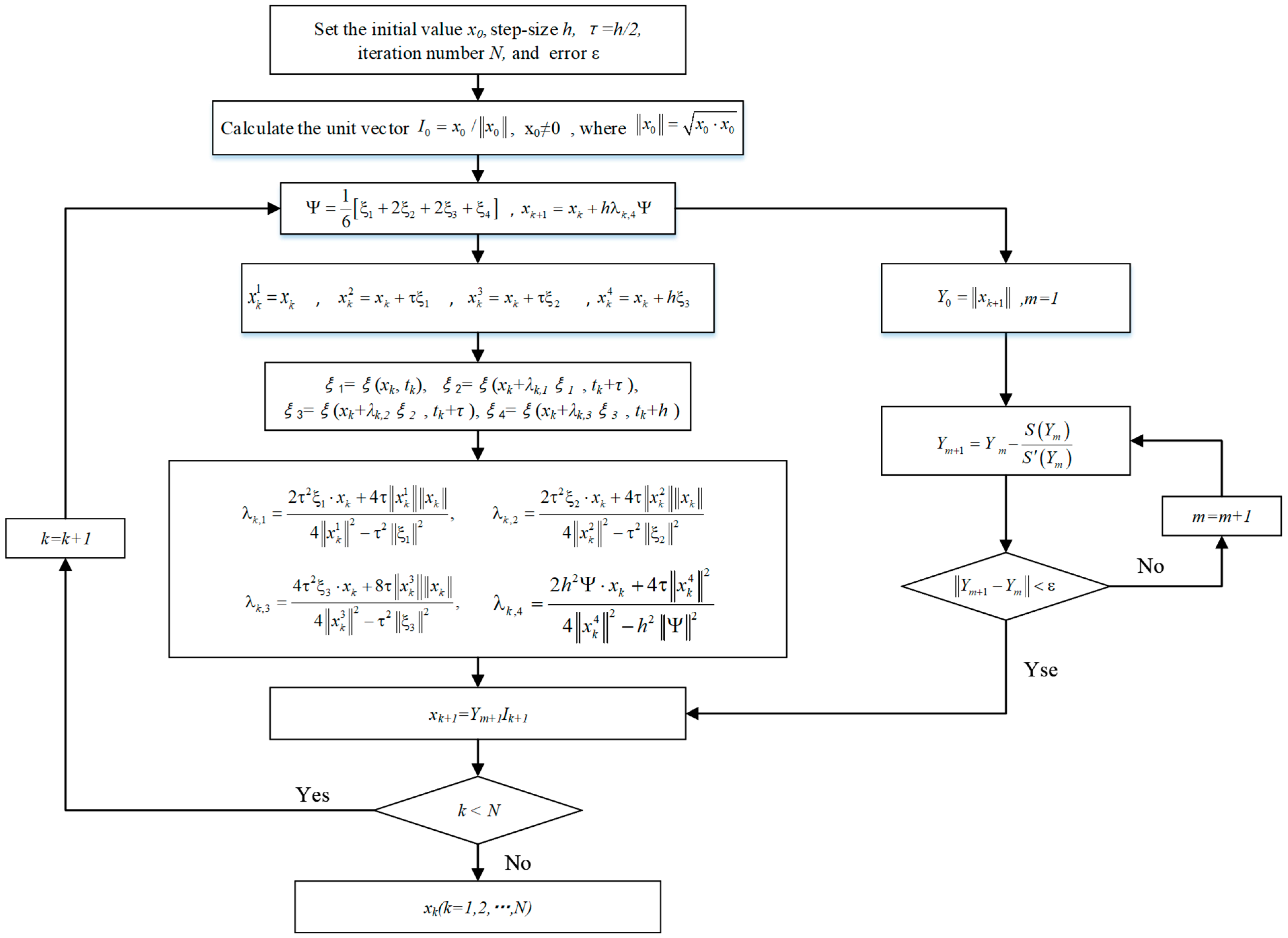
The Runge–Kutta method was proposed by C. Runge and M. W. Kutta in 1900, and belongs to a single-step iterative method [35]. It is able to suppress cumulative errors and has the advantage of high arithmetic accuracy. The four points located on the cone can be defined as:
where h is the step size, and τ = h/2. Here, we define the variable as follows.
Then, the slope values for these aforementioned points can be calculated by
where λk,1, λk,2 and λk,3 are the regulation coefficients for the corresponding slope values. The detailed computational procedure is listed in Figure 5, and the solution’s xk can be regarded as the control law for the motor.
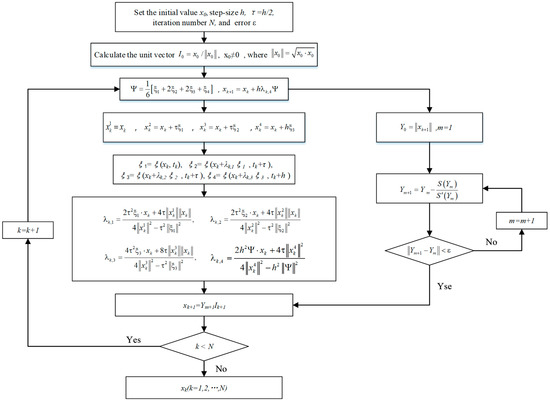
Figure 5.
Computational procedure of the sliding mode control based on group-preserving scheme.
3.2. Control Strategy for the Engine
To avoid the disturbance torque generated from the large speed difference of the clutch, the engine was operated in the mode of speed regulation in this study. The driving plate of the clutch should be maintained to follow the speed of the driven plate.
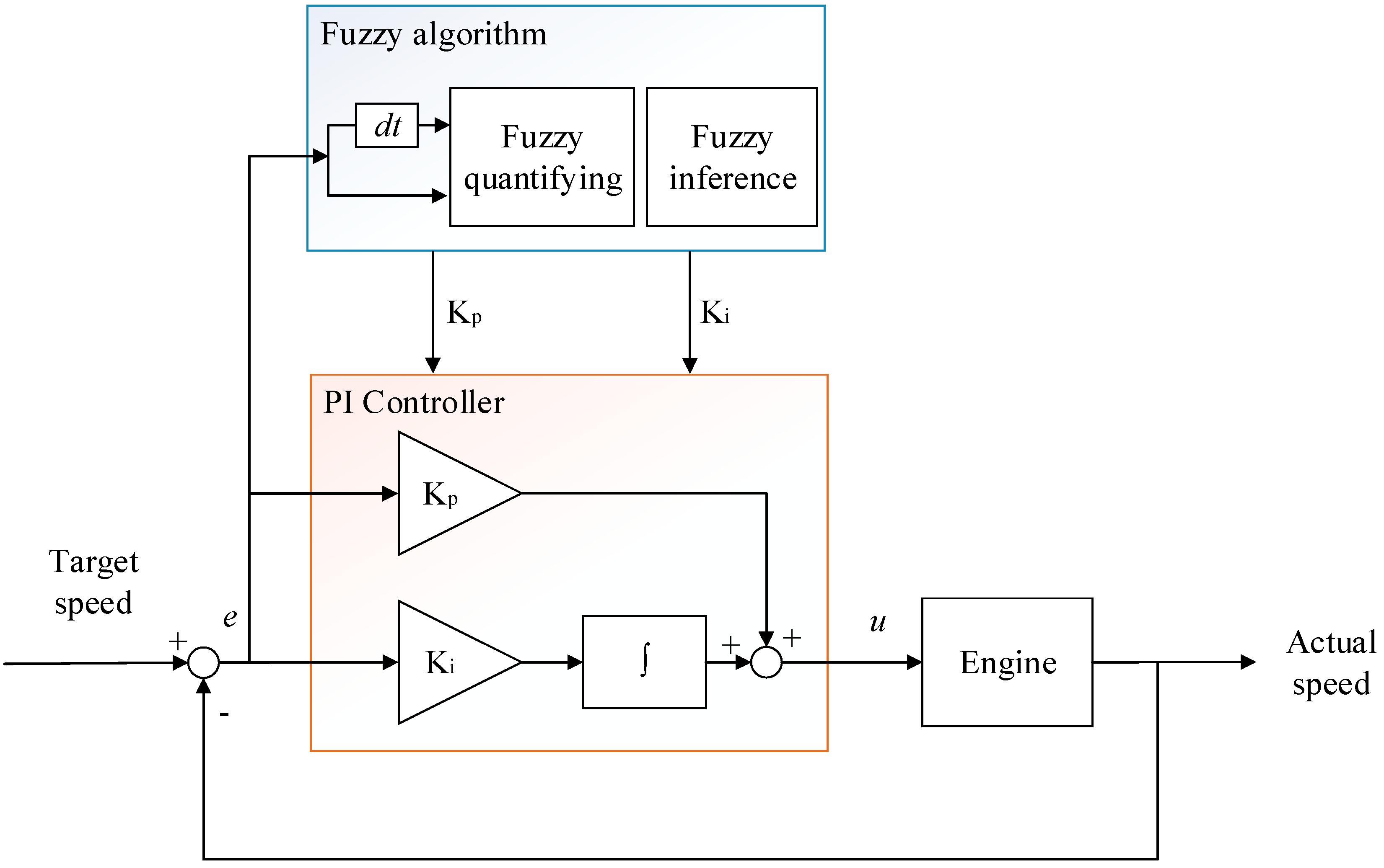
As far as we know, conventional PI controllers with fixed parameters are not suitable for regulating the engine speed because of their complicated dynamic characteristics [36,37,38]. The parameters of the controller must be adjusted according to the actual operating state of the engine. Here, a fuzzy algorithm was introduced and applied in the PI controller to form an adaptive method, rather than the method with fixed parameters. The engine speed control principle diagram is depicted in Figure 6.
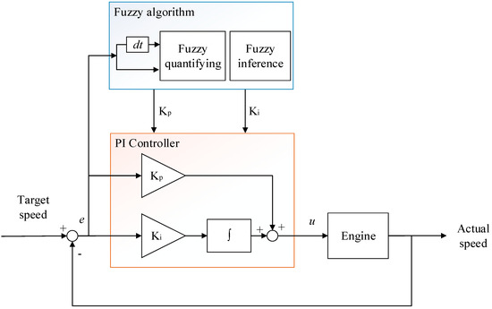
Figure 6.
Architecture of the adaptive PI controller.
To improve the dynamic response of the engine speed regulation, eliminate integral saturation phenomenon, and avoid overshoot and oscillation of the engine speed, the fuzzy algorithm was adopted to correct parameters of the PI controller. The PI controller can be expressed as:
where Kp denotes the proportional coefficient, Ki denotes the integral coefficient, ωe_cmd denotes the target speed for the engine, and e(t) denotes the speed error at the time t.
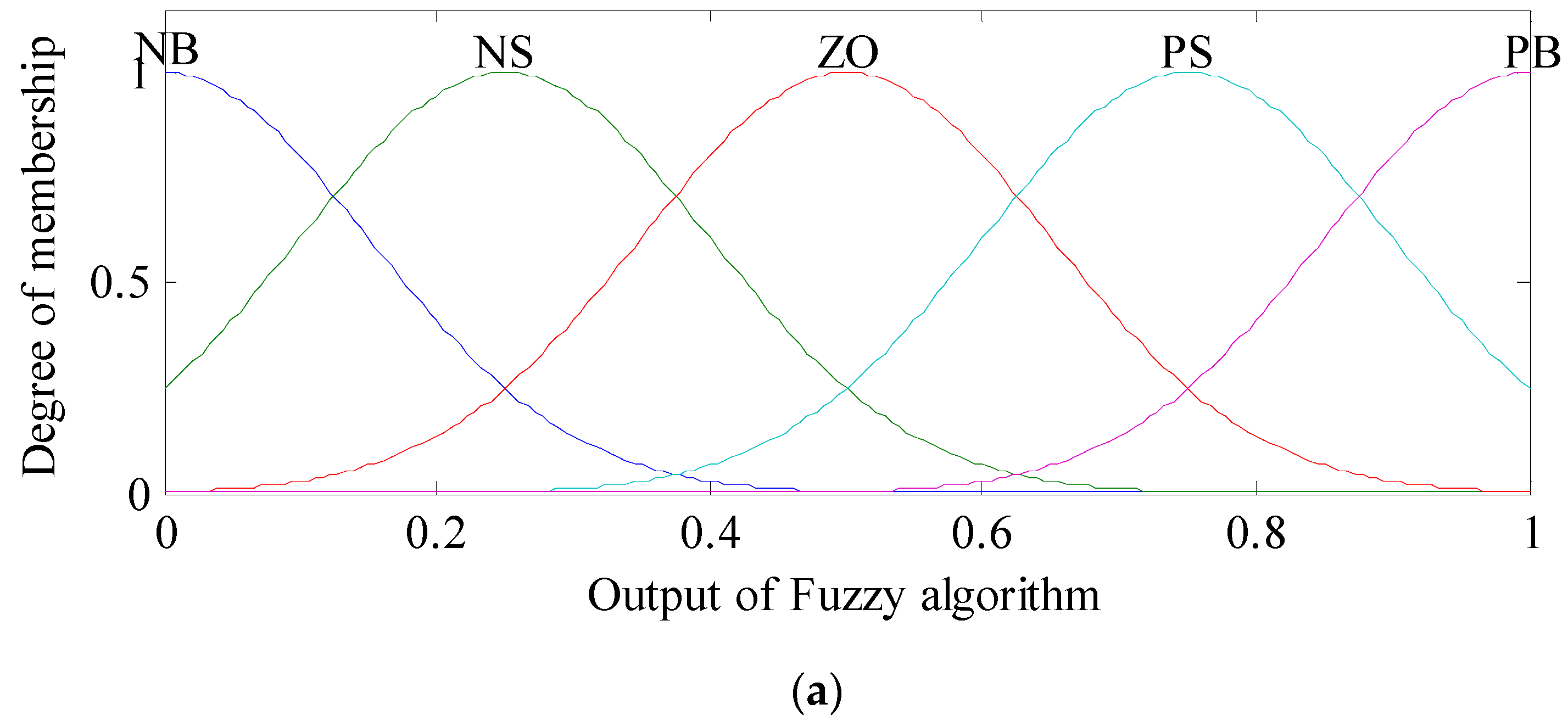
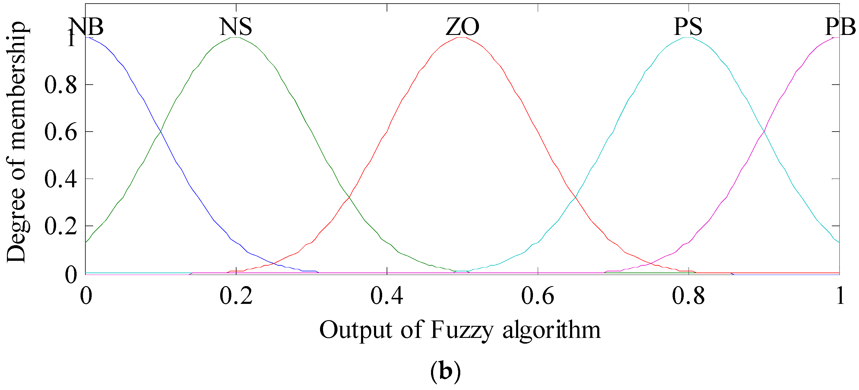
The parameters Kp and Ki of the controller can be normalized by Equations (22) and (23); then, the normalized parameters and in the interval [0, 1] are generated, which can be represented by the fuzzy sets {NB, NS, ZO, PS, PB}. Figure 7 shows their corresponding membership functions.
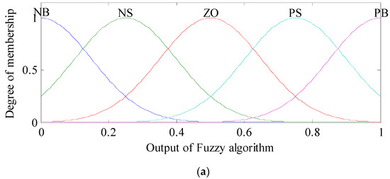
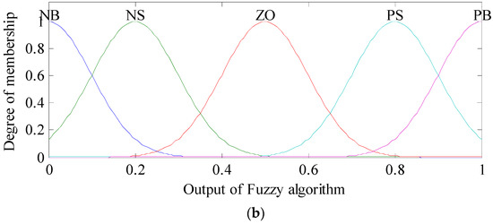
Figure 7.
Membership functions of parameters: (a) and (b) .
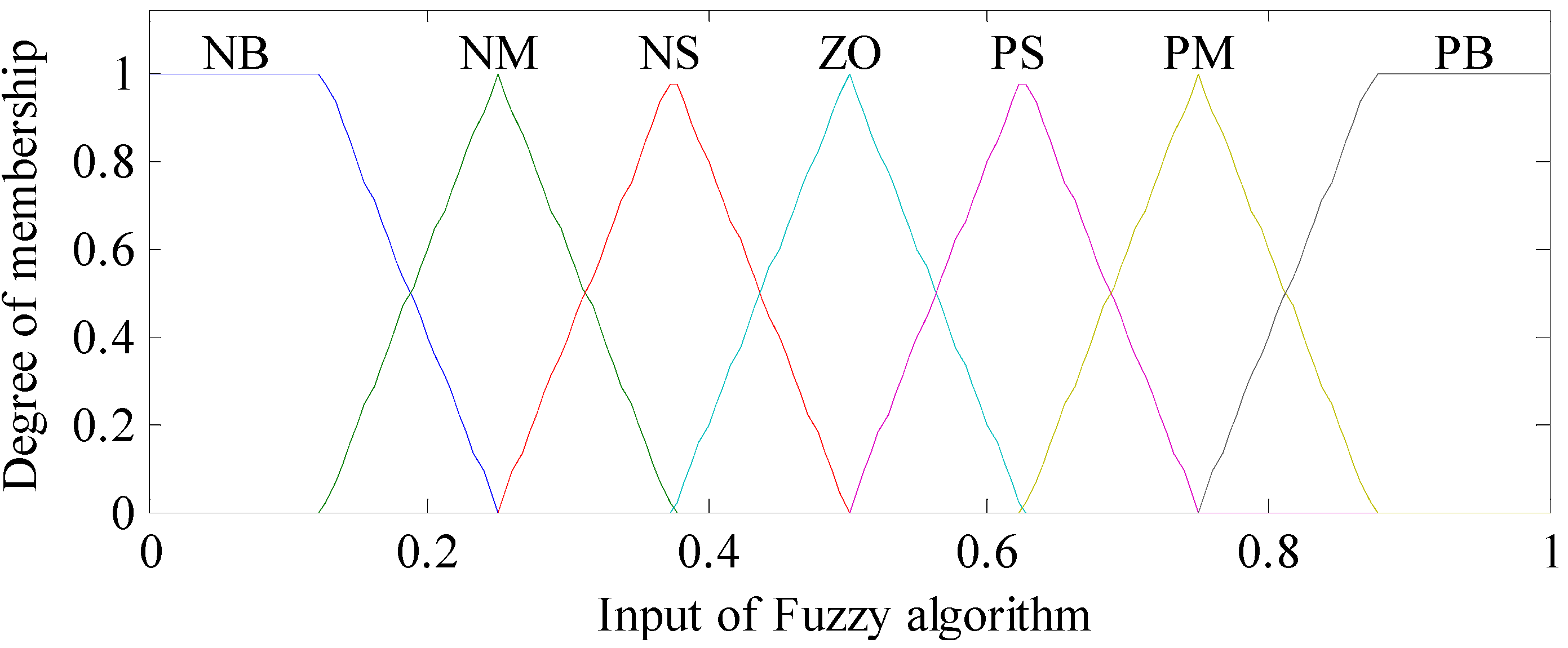
The speed error e and its derivative are regarded as the inputs, which can be expressed by the fuzzy sets {NB, NM, NS, ZO, PS, PM, PB}. Their membership functions are shown in Figure 8. The fuzzy inference rules for parameters and are listed in Table 2 and Table 3, respectively. Finally, accurate parameters for the PI controller were achieved by the defuzzification. In this study, the height method was applied to calculate PI controller parameters, which can be expressed as [39]:
where is fuzzy sets, yn is fuzzy singletons, xi is the input variable, and M stands for the number of inference rules.
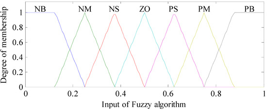
Figure 8.
Membership functions for speed error e and derivative .
Table 2.
Fuzzy inference rules for the parameter .
Table 3.
Fuzzy inference rules for the parameter .
4. Results and Discussion
In order to validate the performance of the proposed strategy, the conducted HIL simulations are described in this section. The verification platform included a real-time parallel HEV model platform and a real-time control platform. Both of the two development platforms can generate the C code and perform online calibration in the MATLAB/Simulink environment [40].
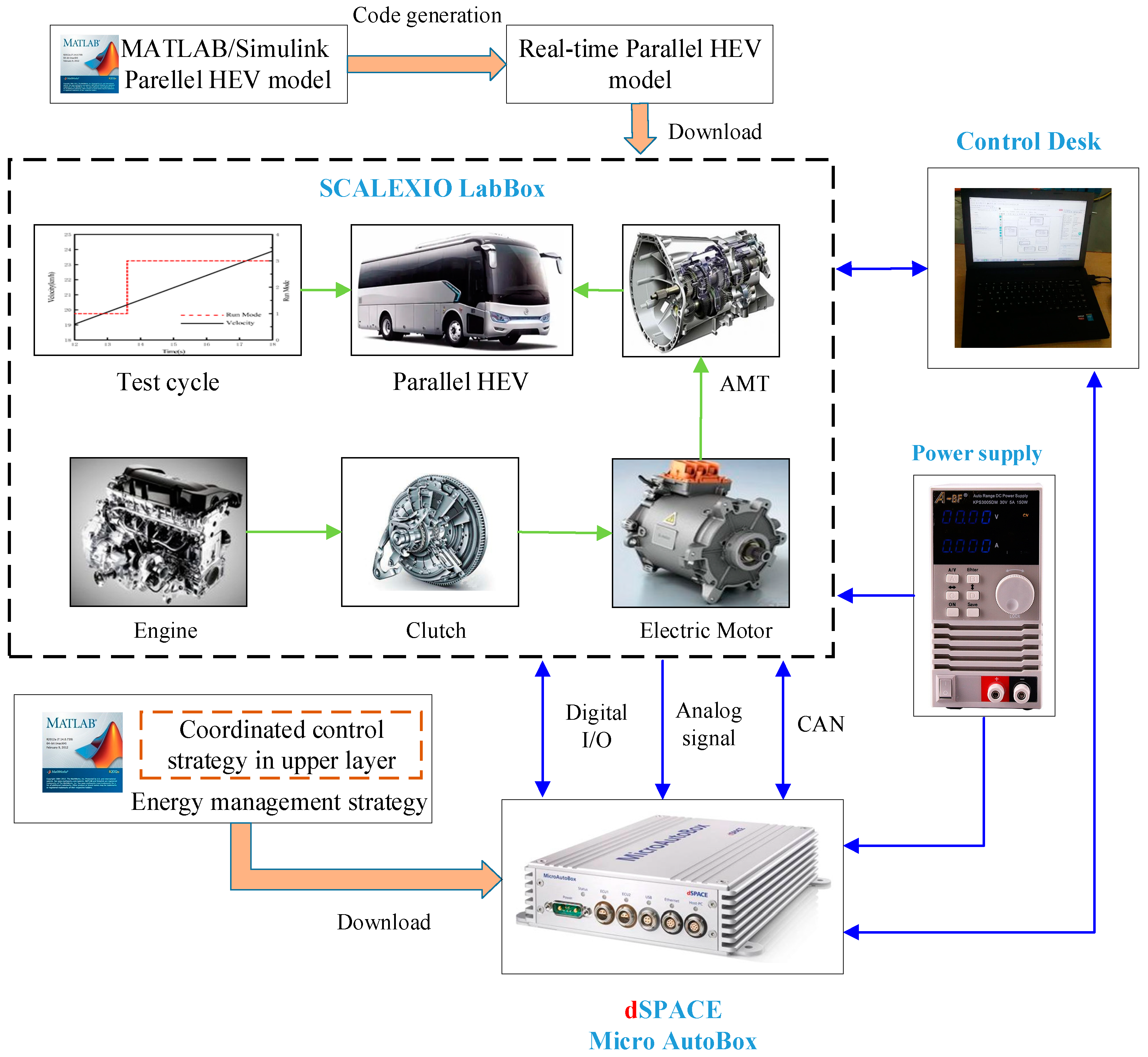
In this study, the development process of the verification platform could be divided into three steps. First, both the parallel HEV model and the control strategy were designed in the MATLAB/Simulink environment. Second, by using the automatic code generation technology, the real-time kernels of the parallel HEV model and control strategy were generated. Third, the real-time kernel of the parallel HEV was downloaded into the SCALEXIO LabBox, which exhibits a strong computing capacity. In addition, the other kernel was flashed into the MicroAutobox, which is an electronic controller [41,42]. All set parameters and verification results in SCALEXIO LabBox and MicroAutobox were monitored by the software Control Desk operating on a laptop [40,41,42,43]. The HIL test bench is depicted in Figure 9.
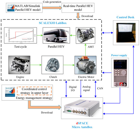
Figure 9.
HIL test bench.
As shown here, the unified model of parallel HEV was constructed with the specifications listed in Table 1. The test cycle was taken from a stretch of typical driving cycles that are widely used by manufacturers, as shown in Figure 9. The whole testing process consisted of the mode transition from the electric mode to the hybrid driving mode. When the vehicle velocity reached about 20 km/h, the engine was dragged to the idle speed by the starting motor and immediately ignited with fuel injection. The clutch was then engaged. After the clutch lockup, the parallel HEV entered the hybrid driving mode. To prove the effectiveness of the proposed coordinated control strategy, the performances of three different cases are compared in this section. A detailed description of three test cases is listed in Table 4.
Table 4.
Description of three test cases.
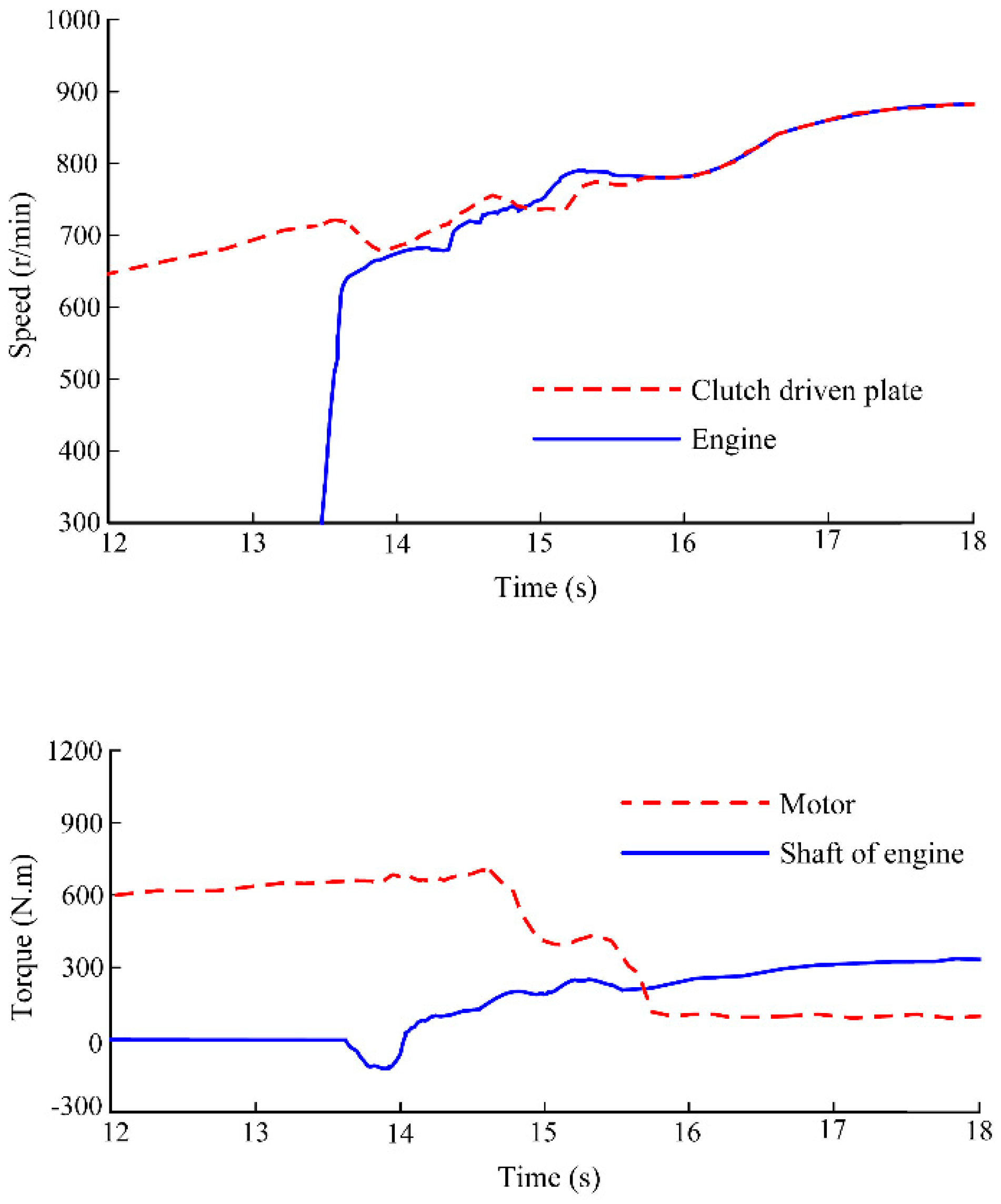
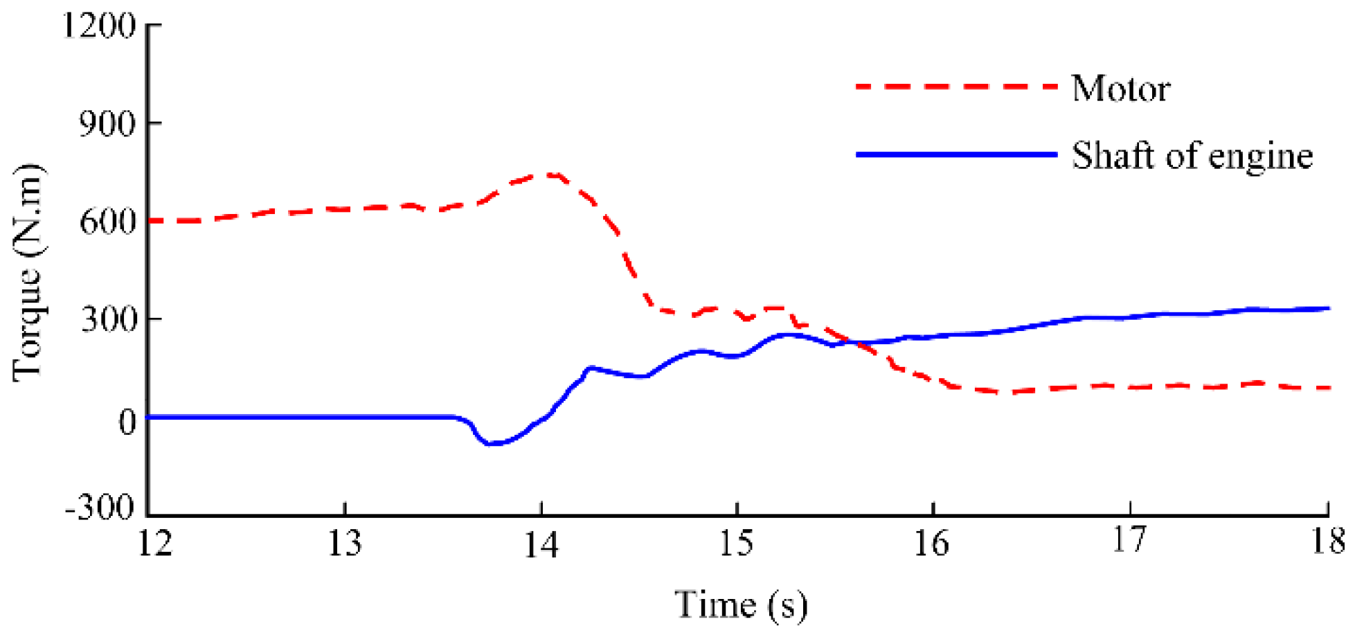
The simulation results for the two power sources for case I are shown in Figure 10. Because the coordinated control strategy was not considered in case I, the control commands for the engine and motor came directly from the energy management strategy. It can be observed that the mode transition occurred around 13.62 s. At the initial stage of the clutch slipping process, the driven plate speed was immediately reduced by about 89 r/min due to the speed difference of the clutch. At this moment, the torque transmitted by the clutch is regarded as an interference torque, which corresponds to a negative torque (−98.7 Nm) on the output shaft of the engine. If this disturbance torque cannot be suppressed or compensated in time, it will lead to a noticeable jerk and vibration in the hybrid powertrain. This means that the coupling torque on the driveshaft does not correspond to the torque required by the powertrain, which results in a large deviation from the actual velocity to the target value. In addition, the variation in the friction plate coefficient with temperature interacts with the engine torque on the driving plate side, which exacerbates the speed fluctuations at both ends of the clutch. Until 15.69 s later, the clutch was completely engaged and in a locked state. With the gradual increase in engine torque, the motor torque decreased to 100 Nm, and the parallel HEV completed the mode transition.
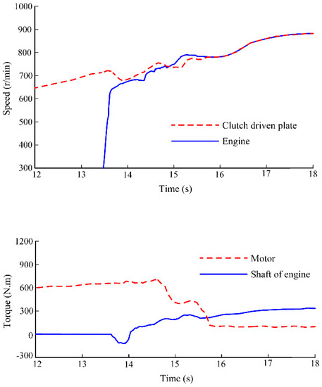
Figure 10.
HIL results for case I.
For case II, the SMC method was used to regulate the motor torque, and the engine still followed control commands that came from the vehicle energy management strategy. It can be seen from Figure 11 that the speed of driven plate decreased by about 43 r/min. This still adversely affected the vehicle performance during the clutch slipping process. Although the control strategy for the motor had a positive effect on depressing the disturbance torque, the fluctuation in engine speed cannot be ignored in this case. Hence, the dynamic responses of the engine should be taken into consideration.
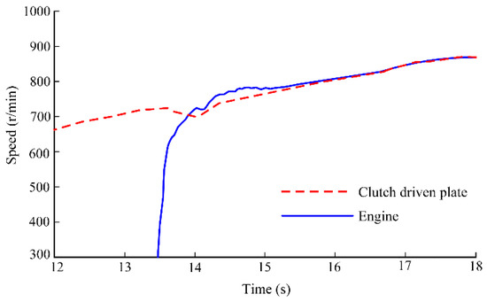
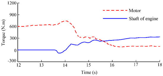
Figure 11.
HIL results for case II.
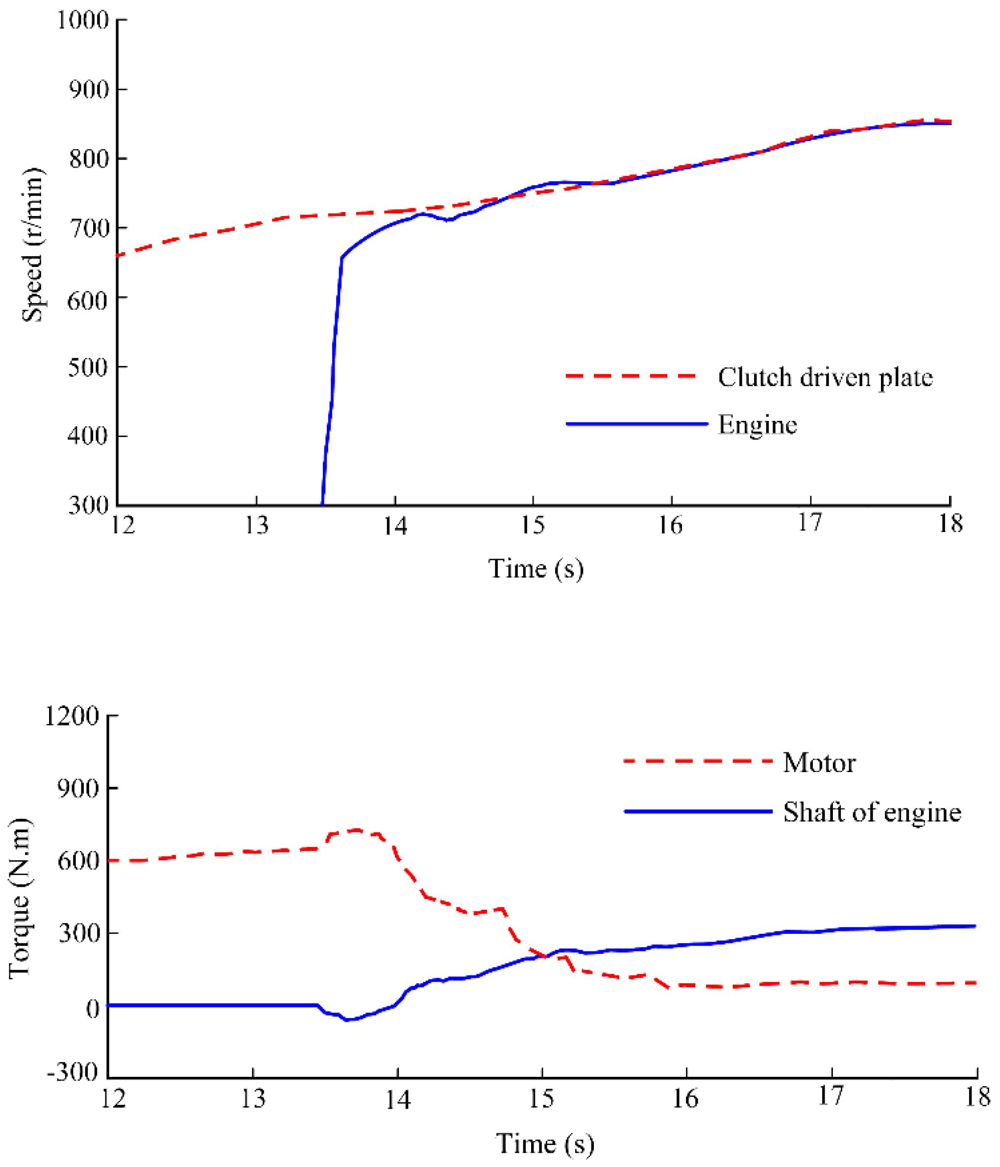
The proposed coordinated control strategy was verified and taken as case III, whose verification results are shown in Figure 12. Similarly, when the velocity was greater than 20 km/h, the engine was dragged to the idle speed by the starting motor. At the engine side, an adaptive PI control strategy based on fuzzy algorithm was adopted to adjust engine speed to synchronize with the driven plate speed and reduce the speed difference of the clutch. The motor was controlled to compensate for the disturbance torque based on the SMC-GP method. From Figure 12, it is seen that the proposed coordinated control strategy exhibited a better control performance in terms of the speed and torque output from both power sources among the parallel HEV.
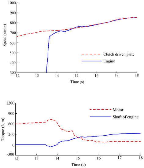
Figure 12.
HIL results for case III.
As is well-known, vehicle jerk and clutch frictional loss are two important criteria that are widely used to quantitatively evaluate the control strategy performance for mode transitions [44,45,46]. Jerk is defined as the derivative of vehicle acceleration, as shown in Equation (25). Vehicle jerk with a large value denotes that the driveline torque occurs as an obvious fluctuation phenomenon, and it will result in the deterioration of the vehicle’s drivability and smoothness. The recommended value is less than 17.64 m/s3 in China and 10 m/s3 in Germany, respectively [47,48,49].
where J is the vehicle jerk, a is the vehicle acceleration, and v is the vehicle velocity determined by the driving cycle.
Clutch frictional loss indicates the work done by friction during the clutch slipping process, which is closely related to the clutch lifespan. The clutch frictional loss Wf can be written as:
where t1 and t2 stand for initial time and end time of the clutch slipping process, respectively.
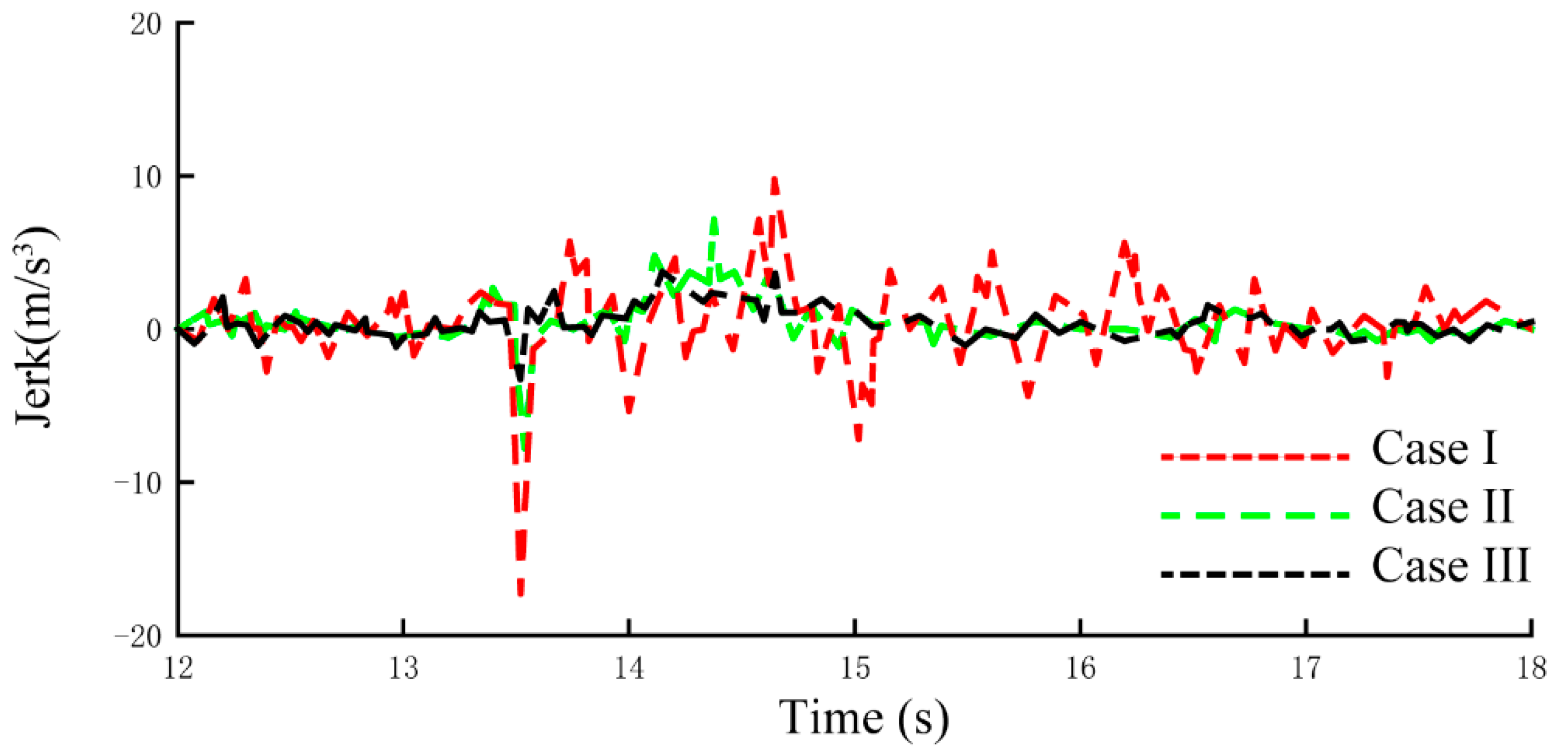
Figure 13 shows the vehicle jerks for the three cases, and their performance comparisons are summarized in Table 5. Due to the influence of disturbance torque and diversity of dynamic responses between the two power sources, the maximum vehicle jerk during the clutch slipping process reached up to 18.81 m/s3 for case I. In addition, vehicle jerk fluctuations further deteriorated the drivability and smoothness performance. In case II, the maximum vehicle jerk could be reduced to 7.65 m/s3 when the SMC method was used to control motor to compensate for the disturbance torque. However, the clutch frictional loss reached up to 4.983 kJ. The black dashed line represents the jerk for case III in Figure 13. It can be observed that by using the proposed strategy, the vehicle jerk was significantly reduced. The clutch frictional loss in case III was only 1.897 kJ, which avoids the unnecessary energy loss and prolongs the clutch lifespan. Additionally, the maximum vehicle velocity error was also restricted to an acceptable range. Hence, the performance comparison for the three cases validates the effectiveness of the proposed strategy in terms of the smoothness and drivability improvement.
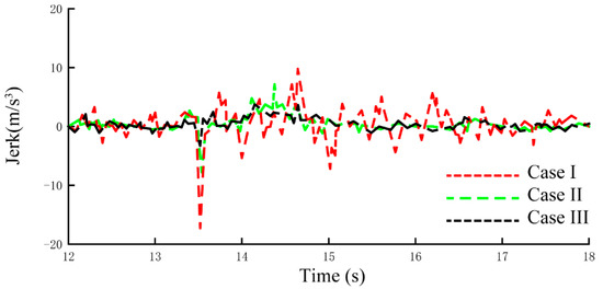
Figure 13.
Vehicle jerks for the three cases.
Table 5.
Performance comparison for the three cases.
5. Conclusions
This paper presents a novel coordinated control strategy to address the deterioration of vehicle smoothness and drivability during the clutch slipping process. The strategy was combined with the motor control and engine control, taking both torque disturbances and model uncertainty into account. Based on the GP-SMC method, a suitable controller for the motor was designed to reduce torque interruption. The dynamic differential equations of the vehicle were constructed by means of the sliding surface with the Lagrange function, and solutions with an accuracy of O (h4) were obtained by using the Runge–Kutta method. Meanwhile, an adaptive PI controller was constructed to adjust the engine speed to reduce the speed difference of the clutch during the slipping process. To verify the effectiveness of the proposed coordinated control strategy, a control model was formulated in the MATLAB/Simulink environment, and HIL simulations were carried out. The results demonstrate that the expected smoothness and drivability of a parallel HEV could be obtained. The vehicle jerk under the proposed coordinated control was limited to 4 m/s3, while the value without coordinated control was 18.81 m/s3. The clutch frictional losses were also effectively reduced, which will extend the clutch lifespan. Although the complexity of the proposed algorithm increased, it was still acceptable. Hence, the proposed coordinated control strategy helps to improve the performance of parallel HEVs and promote their application in the automotive industry. For future work, the system delay and parameter sensitivity studies will be involved to improve the robustness and performance of the coordinated control strategy.
Author Contributions
Conceptualization, S.X. and X.T.; methodology, C.W. and Y.Q.; validation, X.L., J.Z. and T.H.; writing—original draft preparation, S.X., X.T. and X.S.; supervision, X.T. and X.S. All authors have read and agreed to the published version of the manuscript.
Funding
This work was supported by the Foundation for the Jiangsu Key Laboratory of Traffic and Transportation Security (No. TTS2021-02), the sponsored project of Jiangsu province Six Talent Peaks (grant no. XNYQC-002) and the Key R & D projects of Huai’an (grant no. HAG201912).
Institutional Review Board Statement
Not applicable.
Informed Consent Statement
Not applicable.
Data Availability Statement
Not applicable.
Conflicts of Interest
The authors declare no conflict of interest.
Nomenclature
| t | combined inertia of the engine and accessories |
| Jw | inertia of wheels |
| ωm | motor speed |
| bm | motor internal friction coefficient |
| bw | tire damping coefficient |
| i0 | gear ratio of the final drive |
| ks | spring coefficient of the driveline |
| Te | engine torque |
| Tc | clutch torque |
| g | gravity acceleration |
| fr | rolling resistance coefficient |
| A | frontal area |
| va | vehicle velocity |
| Ti | input torque of the driving plate |
| Nc | friction plate number |
| R | outer radius of the diaphragm spring |
| △ω | speed difference |
| u(t) | control input |
| tf | terminal time |
| U | maximum of control input |
| α | positive constant |
| xd | ideal trajectory |
| k | constant with a positive value |
| d | disturbance |
| σ | positive constant with a smaller value |
| Tm_max | maximum motor torque |
| λk,1 | regulation coefficient for slope value 1 |
| λk,2 | regulation coefficient for slope value 2 |
| λk,3 | regulation coefficient for slope value 3 |
| Ki | integral coefficient |
| e(t) | speed error at the time t |
| Kp_min | minimum of the parameter Kp |
| Ki_min | minimum of the parameter Ki |
| yn | fuzzy singletons |
| M | number of inference rules |
| v | vehicle velocity determined by the driving cycle |
| t1 | initial time of the clutch slipping process |
| J | vehicle jerk |
| N | iteration number |
| Jm | combined inertia of the motor rotor and transmission |
| ωe | engine speed |
| ωw | wheel speed |
| be | engine friction coefficient |
| ig | gear ratio of the AMT |
| bs | equivalent damping coefficient of the driveline |
| θs | torsional displacement of the driveshaft |
| Tm | motor torque |
| TL | vehicle load torque |
| m | gross mass |
| θ | road slope angle |
| CD | air drag coefficient |
| δ | modified coefficient of the rotating mass |
| uc | clutch friction coefficient |
| Fc | normal force |
| r | inside radius of the diaphragm spring |
| x(t) | system state |
| t0 | initial time |
| J(u) | performance function |
| M0 | positive constant |
| S(x) | sliding surface |
| ωwd | expected wheel speed |
| u1 | control law |
| χ | positive constant |
| Rw | wheel radius |
| h | step size |
| Kp | proportional coefficient |
| ωe_cmd | target speed for engine |
| Kp_max | maximum of the parameter Kp |
| Ki_max | maximum of the parameter Ki |
| fuzzy sets | |
| xi | input variable |
| a | vehicle acceleration |
| Wf | clutch frictional loss |
| t2 | end time of the clutch slipping process |
| F(x(tf), tf) | terminal index function |
| L(x, u, t) | Lagrange function |
References
- Agamloh, E.; Von Jouanne, A.; Yokochi, A. An Overview of Electric Machine Trends in Modern Electric Vehicles. Machines 2020, 8, 20. [Google Scholar] [CrossRef]
- Tian, X.; Cai, Y.; Sun, X.; Zhu, Z.; Xu, Y. A Novel Energy Management Strategy for Plug-in Hybrid Electric Buses Based on Model Predictive Control and Estimation of Distribution Algorithm. IEEE/ASME Trans. Mechatron. 2022, 1–12. [Google Scholar] [CrossRef]
- Mercorelli, P. Parameter identification in a permanent magnet three-phasesynchronous motor of a city bus for an intelligent drive assistant. Int. J. Model. Identif. Control 2014, 21, 352–361. [Google Scholar] [CrossRef]
- Wang, Z.; Cai, Y.; Zeng, Y.; Yu, J. Multi-objective optimization for plug-in 4WD hybrid electric vehicle powertrain. Appl. Sci. 2019, 9, 4068. [Google Scholar] [CrossRef]
- Morales-Morales, J.; Rivera-Cruz, M.A.; Cruz-Alcantar, P.; Santos, H.B.; Cervantes-Camacho, I.; Herrera, V.A.R. Performance Analysis of a Hybrid Electric Vehicle with Multiple Converter Configuration. Appl. Sci. 2020, 10, 1074. [Google Scholar] [CrossRef]
- Ebbesen, S.; Elbert, P.; Guzzella, L. Battery State-of-Health Perceptive Energy Management for Hybrid Electric Vehicles. IEEE Trans. Veh. Technol. 2012, 61, 2893–2900. [Google Scholar] [CrossRef]
- Tang, X.; Yang, W.; Hu, X.; Zhang, D. A novel simplified model for torsional vibration analysis of a series-parallel hybrid electric vehicle. Mech. Syst. Signal Process. 2017, 85, 329–338. [Google Scholar] [CrossRef]
- Nüesch, T.; Elbert, P.; Flankl, M.; Onder, C.H.; Guzzella, L. Convex Optimization for the Energy Management of Hybrid Electric Vehicles Considering Engine Start and Gearshift Costs. Energies 2014, 7, 834–856. [Google Scholar] [CrossRef]
- Sun, X.; Shi, Z.; Zhu, J. Multiobjective Design Optimization of an IPMSM for EVs Based on Fuzzy Method and Sequential Taguchi Method. IEEE Trans. Ind. Electron. 2020, 68, 10592–10600. [Google Scholar] [CrossRef]
- Koprubasi, K.; Westervelt, E.R.; Rizzoni, G. Toward the Systematic Design of Controllers for Smooth Hybrid Electric Vehicle Mode Changes. In Proceedings of the 2007 American Control Conference, New York, NY, USA, 9–13 July 2007; pp. 2985–2990. [Google Scholar] [CrossRef]
- Chen, L.; Xi, G.; Sun, J. Torque Coordination Control During Mode Transition for a Series–Parallel Hybrid Electric Vehicle. IEEE Trans. Veh. Technol. 2012, 61, 2936–2949. [Google Scholar] [CrossRef]
- Zhang, H.; Wang, C.-L.; Zhang, Y.; Liang, J.-Y.; Yin, C.-L. Drivability improvements for a single-motor parallel hybrid electric vehicle using robust controls. J. Zhejiang Univ. A 2014, 15, 291–301. [Google Scholar] [CrossRef]
- Kim, H.; Kim, J.; Lee, H. Mode Transition Control Using Disturbance Compensation for a Parallel Hybrid Electric Vehicle. Proc. Inst. Mech. Eng. Part D J. Automob. Eng. 2011, 225, 150–166. [Google Scholar] [CrossRef]
- Yang, C.; Jiao, X.; Li, L.; Zhang, Y.; Chen, Z. A robust H∞ control-based hierarchical mode transition control system for plug-in hybrid electric vehicle. Mech. Syst. Signal Process. 2018, 99, 326–344. [Google Scholar] [CrossRef]
- Zeng, X.; Yang, N.; Wang, J.; Song, D.; Zhang, N.; Shang, M.; Liu, J. Predictive-model-based dynamic coordination control strategy for power-split hybrid electric bus. Mech. Syst. Signal Process. 2015, 60–61, 785–798. [Google Scholar] [CrossRef]
- Michalek, M.M.; Patkowski, B.; Gawron, T. Modular Kinematic Modelling of Articulated Buses. IEEE Trans. Veh. Technol. 2020, 69, 8381–8394. [Google Scholar] [CrossRef]
- Sun, X.; Cai, F.; Yang, Z.; Tian, X. Finite Position Control of Interior Permanent Magnet Synchronous Motors at Low Speed. IEEE Trans. Power Electron. 2022, 37, 7729–7738. [Google Scholar] [CrossRef]
- Suhail, M.; Akhtar, I.; Kirmani, S.; Jameel, M. Development of Progressive Fuzzy Logic and ANFIS Control for Energy Management of Plug-In Hybrid Electric Vehicle. IEEE Access 2021, 9, 62219–62231. [Google Scholar] [CrossRef]
- Tian, X.; He, R.; Sun, X.; Cai, Y.; Xu, Y. An ANFIS-Based ECMS for Energy Optimization of Parallel Hybrid Electric Bus. IEEE Trans. Veh. Technol. 2019, 69, 1473–1483. [Google Scholar] [CrossRef]
- Ji, Y.; Lee, H. Event-Based Anomaly Detection Using a One-Class SVM for a Hybrid Electric Vehicle. IEEE Trans. Veh. Technol. 2022, 71, 6032–6043. [Google Scholar] [CrossRef]
- Sun, X.; Shi, Z.; Cai, Y.; Lei, G.; Guo, Y.; Zhu, J. Driving-Cycle-Oriented Design Optimization of a Permanent Magnet Hub Motor Drive System for a Four-Wheel-Drive Electric Vehicle. IEEE Trans. Transp. Electrif. 2020, 6, 1115–1125. [Google Scholar] [CrossRef]
- Bhattacharjee, S.; Halder, S.; Yan, Y.; Balamurali, A.; Iyer, L.V.; Kar, N.C. Real-Time SIL Validation of a Novel PMSM Control Based on Deep Deterministic Policy Gradient Scheme for Electrified Vehicles. IEEE Trans. Power Electron. 2022, 37, 9000–9011. [Google Scholar] [CrossRef]
- Wang, L.; Zhang, Y.; Yin, C.; Zhang, H.; Wang, C. Hardware-in-the-loop simulation for the design and verification of the control system of a series–parallel hybrid electric city-bus. Simul. Model. Pract. Theory 2012, 25, 148–162. [Google Scholar] [CrossRef]
- Hong, S.; Kim, H.; Kim, J. Motor control algorithm for an optimal engine operation of power split hybrid electric vehicle. Int. J. Automot. Technol. 2015, 16, 97–105. [Google Scholar] [CrossRef]
- Sun, X.; Cao, J.; Lei, G.; Guo, Y.; Zhu, J. A Composite Sliding Mode Control for SPMSM Drives Based on a New Hybrid Reaching Law With Disturbance Compensation. IEEE Trans. Transp. Electrif. 2021, 7, 1427–1436. [Google Scholar] [CrossRef]
- Serrao, L.; Onori, S.; Rizzoni, G. A Comparative Analysis of Energy Management Strategies for Hybrid Electric Vehicles. J. Dyn. Syst. Meas. Control 2011, 133, 031012. [Google Scholar] [CrossRef]
- Sun, X.; Zhang, Y.; Lei, G.; Guo, Y.; Zhu, J. An Improved Deadbeat Predictive Stator Flux Control with Reduced-Order Disturbance Observer for In-Wheel PMSMs. IEEE/ASME Trans. Mechatron. 2021, 27, 690–700. [Google Scholar] [CrossRef]
- Pathmanathan, M.; Semsar, S.; Viana, C.; Lehn, P.W. Power Sharing Control Algorithm for Direct Integration of Fuel Cells in a Dual-Inverter Electric Vehicle Drivetrain. IEEE Trans. Transp. Electrif. 2022, 8, 2490–2500. [Google Scholar] [CrossRef]
- Zhou, Q.; Yao, D.; Wang, J.; Wu, C. Robust control of uncertain semi-Markovian jump systems using sliding mode control method. Appl. Math. Comput. 2016, 286, 72–87. [Google Scholar] [CrossRef]
- Jin, Z.; Sun, X.; Lei, G.; Guo, Y.; Zhu, J. Sliding Mode Direct Torque Control of SPMSMs Based on a Hybrid Wolf Optimization Algorithm. IEEE Trans. Ind. Electron. 2021, 69, 4534–4544. [Google Scholar] [CrossRef]
- Krueger, B.; Filomeno, G.; Golle, A.; Dennin, D.; Tenberge, P. Unified Mode-Based Description of Arbitrary Hybrid and Electric Powertrain Topologies. IEEE Trans. Veh. Technol. 2021, 71, 1293–1306. [Google Scholar] [CrossRef]
- Tian, X.; Cai, Y.; Sun, X.; Zhu, Z.; Xu, Y. An adaptive ECMS with driving style recognition for energy optimization of parallel hybrid electric buses. Energy 2019, 189, 116151. [Google Scholar] [CrossRef]
- Liu, C.-S. Cone of non-linear dynamical system and group preserving schemes. Int. J. Non-Linear Mech. 2001, 36, 1047–1068. [Google Scholar] [CrossRef]
- Lu, J.; Tang, J.; Qin, X.; Feng, Y. Modified group preserving methods and applications in chaotic systems. Acta Phys. Sin. 2016, 65, 11–19. [Google Scholar]
- Hager, W.W. Runge-Kutta methods in optimal control and the transformed adjoint system. Numer. Math. 2000, 87, 247–282. [Google Scholar] [CrossRef]
- Huang, C.; Chen, L.; Jiang, H.B.; Yuan, C.C.; Xia, T. Nonlinear Analysis and Intelligent Control of Integrated Vehicle Dynamics. Math. Probl. Eng. 2014, 2014, 832864. [Google Scholar] [CrossRef]
- Mura, R.; Utkin, V.; Onori, S. Energy Management Design in Hybrid Electric Vehicles: A Novel Optimality and Stability Framework. IEEE Trans. Control Syst. Technol. 2015, 23, 1307–1322. [Google Scholar] [CrossRef]
- Tian, X.; Cai, Y.; Sun, X.; Zhu, Z.; Wang, Y.; Xu, Y. Incorporating Driving Style Recognition into MPC for Energy management of Plug-in Hybrid Electric Buses. IEEE Trans. Transp. Electrif. 2022, 1. [Google Scholar] [CrossRef]
- Ferrara, A.; Hametner, C. Impact of energy management strategies on hydrogen consumption and start-up/shut-down cycles in fuel cell-ultracapacitor-battery vehicles. IEEE Trans. Veh. Technol. 2022, 7, 5692–5703. [Google Scholar] [CrossRef]
- Sun, J.; Xing, G.; Liu, X.; Fu, X.; Zhang, C. A Novel Torque Coordination Control Strategy of a Single-Shaft Parallel Hybrid Electric Vehicle Based on Model Predictive Control. Math. Probl. Eng. 2015, 2015, 960678. [Google Scholar] [CrossRef]
- Laurén, M.; Goswami, G.; Tupitsina, A.; Jaiswal, S.; Lindh, T.; Sopanen, J. General-Purpose and Scalable Internal-Combustion Engine Model for Energy-Efficiency Studies. Machines 2021, 10, 26. [Google Scholar] [CrossRef]
- Sun, X.; Li, T.; Yao, M.; Lei, G.; Guo, Y.; Zhu, J. Improved Finite-Control-Set Model Predictive Control with Virtual Vectors for PMSHM Drives. IEEE Trans. Energy Convers. 2021, 1. [Google Scholar] [CrossRef]
- Mironova, A.; Mercorelli, P.; Zedler, A. A multi input sliding mode control for peltier cells using a cold-warm sliding surface. J. Frankl. Inst. 2018, 355, 9351–9373. [Google Scholar] [CrossRef]
- Sun, X.; Cao, J.; Lei, G.; Guo, Y.; Zhu, J. A Robust Deadbeat Predictive Controller With Delay Compensation Based on Composite Sliding-Mode Observer for PMSMs. IEEE Trans. Power Electron. 2021, 36, 10742–10752. [Google Scholar] [CrossRef]
- Muna, Y.B.; Kuo, C.-C. Feasibility and Techno-Economic Analysis of Electric Vehicle Charging of PV/Wind/Diesel/Battery Hybrid Energy System with Different Battery Technology. Energies 2022, 15, 4364. [Google Scholar] [CrossRef]
- Sun, X.; Li, T.; Zhu, Z.; Lei, G.; Guo, Y.; Zhu, J. Speed Sensorless Model Predictive Current Control Based on Finite Position Set for PMSHM Drives. IEEE Trans. Transp. Electrif. 2021, 7, 2743–2752. [Google Scholar] [CrossRef]
- Shabbir, W.; Evangelou, S.A. Threshold-changing control strategy for series hybrid electric vehicles. Appl. Energy 2018, 235, 761–775. [Google Scholar] [CrossRef]
- Li, P.; Jiao, X.; Li, Y. Adaptive real-time energy management control strategy based on fuzzy inference system for plug-in hybrid electric vehicles. Control Eng. Pract. 2020, 107, 104703. [Google Scholar] [CrossRef]
- Hwang, H.S.; Yang, D.H.; Choi, H.K.; Kim, H.S.; Hwang, S.-H. Torque control of engine clutch to improve the driving quality of hybrid electric vehicles. Int. J. Automot. Technol. 2011, 12, 763–768. [Google Scholar] [CrossRef]


Publisher’s Note: MDPI stays neutral with regard to jurisdictional claims in published maps and institutional affiliations. |
© 2022 by the authors. Licensee MDPI, Basel, Switzerland. This article is an open access article distributed under the terms and conditions of the Creative Commons Attribution (CC BY) license (https://creativecommons.org/licenses/by/4.0/).