Article

Alignment Control Reconfigurability Analysis and Autonomous Control Methods of Air Spring Vibration Isolation System for High Power Density Main Engine (HPDME-ASVIS)

1
Institute of Noise & Vibration, Naval University of Engineering, Wuhan 430033, China
2
National Key Laboratory on Ship Vibration & Noise, Wuhan 430033, China
*
Author to whom correspondence should be addressed.
Appl. Sci. 2022, 12(16), 8211; https://doi.org/10.3390/app12168211
Submission received: 16 July 2022 / Revised: 12 August 2022 / Accepted: 15 August 2022 / Published: 17 August 2022

Abstract

:
The alignment stability and controllability deteriorate considerably when the air spring vibration isolation system for the high power density main engine (HPDME-ASVIS) is in a special running state of high power and high output torque. The coupling characteristics among the alignment components are obtained by analyzing the mechanical characteristics of HPDME-ASVIS. A control response model is established, which can predict the alignment state and the vertical displacement of air springs after k times of inflation/deflation. By solving the linear programming problem, the alignment controllability judgment models are constructed for two conditions, which are under hard constraints and soft constraints, respectively. Furthermore, alignment reconfigurability is described and an autonomous control method is established. The experimental results confirm that high output torque will cause large and serious coupling of horizontal offset, self-rotation angle, and vertical deformation of air springs. Meanwhile, hey cannot reach the given control precision range. The traditional control method under hard constraints will result in a state of oscillation and may bring many reliability problems to HPDME-ASVIS. The alignment reconfigurability analysis can judge the alignment control influence degree based on different torque accurately. The autonomous control can use the control parameters autonomous adjustment and the spatial configuration to realize the alignment control reconfigurability for two different alignment control fault states. The stability of the alignment control system in HPDME-ASVIS can be improved observably, which is of great significance to the engineering application of the high power density main engine (HPDME) in the field of marine propulsion technology.

1. Introduction

In the field of high-efficiency vibration isolation of marine propulsion devices, there is a serious conflict between low-frequency vibration isolation and shaft alignment stability [1]. The air spring vibration isolation system (ASVIS) can realize an excellent vibration isolation effect for the main engine. However, at the same time, the safe operation is affected by shaft misalignment, caused by strong disturbances such as output torque [2]. Shaft misalignment is divided into parallel misalignment (offset), angular misalignment (skew), and combined misalignment (including parallel misalignment and angular misalignment). The influence of parallel misalignment is dominant at two times the characteristic frequency [3]. Parallel misalignment shows a stronger 1X axial and torsional response, and the angular misalignment shows a very strong 3X harmonic component in the axial and torsional vibration response at one-third of the critical speed [4]. The control of alignment will affect the isolation effect of the system. He et al. [2] used a simplified impedance method to estimate the isolation effect of the system. In practice, larger shaft misalignments will increase the vibration of the mounting foundation. However, the shaft misalignment has a more significant influence on the safe operation of the device than on the vibration isolation effect. Through a series of studies [5,6,7,8,9], the alignment stability and controllability of the air spring vibration isolation system for the main engine under the conventional running state have been preliminarily solved.
When the new-type high power density main engine is applied to marine [10], there will be a problem of failure control of shaft alignment due to high torques. Compared to a conventional DC motor, the output torque dramatically increases as the power density can rise by dozens of times while the mass of the device changes at a glacial pace [11]. Compared with low parameter conditions, failures occur more prominently in high parameter conditions, such as high pressure, high power, high flow rate, large thrust-weight ratio, and so on [12]. In comparison with the traditional main engine, the alignment control failures of the high power density main engine (HPDME) at high power are more prominent [11]. When the traditional alignment control methods are still used in the HPDME, it will lead to poor alignment stability. The methods of [5,6,7,8,9] did not investigate the case where the output torque reaction is extremely prominent at high power density. It will force the system into an uncontrollable state, which is also known as an alignment control fault state. Therefore, it is necessary to reconfigure this alignment control fault state in the high output torque running state of the ASVIS for the HPDME (HPDME-ASVIS).
With the increased complexity of engineering systems, there are some dynamic characteristics during system failure, such as sequence dependency, functional dependency, and spares [13]. Liu et al. [14] analyzed that the main reason for many serious spacecraft accidents is defects in fault diagnosis and treatment, which are due to the lack of reconfigurability. Wang et al. [15] reviewed and studied the reconfigurability of spacecraft control systems. They define reconfigurability as “the ability of a system to overcome failures and recover all/partial of its established functions by autonomously changing spatial configurations or control algorithms within a safe time under certain resource allocation and operating conditions” [15]. The measure of control reconfigurability can be considered intrinsic reconfigurability [16,17]. Contreras et al. [16] used the controllability gramian under partial failure to estimate system reconfigurability, but this method is only suitable for control systems with limited energy consumption. HUANG et al. [18] pointed out that the reconfigurability is also called the recoverability of failure, and the reconfigurability is evaluated from the perspective of a community, i.e., the system is not reconfigurable if the system cannot find a controllable community.
The reconfigurability modeling methods can be generally classified into four types: based on the residual controllability/observability of faulty systems [16,18,19,20,21,22], based on Bayesian [13,23,24,25], based on the Markov model [26,27,28], based on a multiobjective evolutionary algorithm based on decomposition (MOEA/D) framework [29]. At present, most of the research on reconfigurability is based on the residual controllability/observability of faulty systems [15]. To describe the reconfigurability of HPDME-ASVIS, the alignment controllability should be studied. The alignment control problem is a multi-objective optimization problem with multivariable and multi-constraints. Fu et al. [29] pointed out that objective optimization is a typical trade-off problem where it is cognitively impossible to optimize all conflicting objectives simultaneously. In other words, the optimization of any objective will lead to the degradation of one/more other objectives. Based on the geometric method, Xi and Li [30] proposed a controllability analysis method for the constrained multi-objective multi-degree-of-freedom optimization (CMMO) in a steady state, which solves the high-dimensional space intersection problem (including intersection region estimation) and inequality compatibility problems (including compatibility region estimation). The feasibility of the constrained optimization problem is a prerequisite for a controllability system [31]. Xi and Gu [32] used an algebraic method for solving linear programming problems to judge the feasibility of CMMO. They also propose a CMMO feasibility analysis and soft constraint adjustment algorithm, in which the priority level of the constraint needs to be adjusted by the user. Zhang et al. [33] propose a feasibility analysis and constraint adjustment of automatic constraint optimization control without user participation and demonstrated its effectiveness by a simulation test of a petroleum fractionator. JIANG et al. [34] solved the instability problem of the steam generator system of the nuclear power plant under hard constraints by using soft constraints model predictive control (MPC), which can improve the stability during steam disturbance and large-scale power variation of the unit. Lu et al. [35] guarantee the recursive feasibility of MPC by softening the input constraints and state constraints. K. P. Wabersich et al. [36] propose a soft constraints MPC formulation supporting polytopic invariance region in half-space and climax, which increases the feasible set and improves asymptotic stability significantly. Therefore, alignment controllability can be analyzed by solving linear programming problems, and the soft constraints are expected to solve the alignment control failure of HPDME-ASVIS at high output torque state.
Based on the results of the analysis of the alignment controllability, the reconfigurability is described. Liu and Wang [14] used Fault Reconfigurable Degree (FRD) and System Reconfigurable Rate (SRR) as evaluation indexes for spacecraft reconfigurability, where FRD is a contradictory judgment based on whether the system is reconfigurable or not. The alignment of FRD and SRR are defined, and then the autonomous control is designed.
The overall purpose of this paper is to analyze the reconfigurability of HPDME-ASVIS and propose an automatic control method by analyzing the device mechanics and establishing an alignment control response. The structure of this paper is organized as follows. In Section 2, the device mechanics are analyzed and the research problem is formulated. In Section 3, the alignment control response model is established. In Section 4, the alignment controllability judgment model, reconfigurability analysis, and autonomous control are described. In Section 5, supporting experimental results are provided. In Section 6, some conclusions and future work are presented.

2. Mechanical Analysis and Research Problem

2.1. Preliminary Knowledge

The output torque and the deformation of air springs will affect the shaft alignment attitude, especially the horizontal offset and self-rotation angle of HPDME-ASVIS. Taking HPDME-ASVIS as the research object, the global coordinate system is established as shown in Figure 1, in which the center of gravity is regarded as the origin of the coordinate and the output shaft is regarded as the positive direction of the y-axis.
The air springs are arranged symmetrically with respect to the yoz plane and the xoz plane at the same height. The main engine and foundation are treated as rigid bodies. Each air spring is treated as a linear spring. HPDME-ASVIS dynamics equation can be expressed [2] as
M x ¨ g + K x g = f
where M is the mass matrix of HPDME-ASVIS, x g = [ x g , y g , z g , α , β , χ ] T is the displacement vector of HPDME-ASVIS which includes translational displacements of the center of gravity ( x g , y g and z g ) and angular displacements ( α , β and χ ), K is the global stiffness matrix formed by the stiffness matrix of the air springs and the elastic coupling, and f is the external force vector exerted on HPDME-ASVIS..
The alignment state vector in the coupling center point is
x c = [ x c , y c , z c , α , β , χ ] T
where x c is the horizontal offset, y c is the axial offset, z c is the vertical offset, α is the vertical angularity, β is the self-rotation angle, χ is the horizontal angularity.
Considering the effect of external disturbances as a quasi-static process ( x ¨ g = 0 ), from Equation (1) the displacement response of the HPDME-ASVIS is
x g = K 1 f
The alignment at the coupling center point is
x c = G c x g
where G c is the position transformation matrix of the coupling center point in the global coordinate system.
In previous studies of the ASVIS for the main engine, the alignment control objectives usually include the following three parts [37]. The first is to achieve high precision alignment control at the coupling center point. The second is to control the vertical deformation of the air springs within an acceptable range, and the third is to maintain the load distribution of the air springs as evenly as possible during the control process [37]. As HPDME-ASVIS often operate under special conditions of high power and high output torque, the research problem of this paper is how to offset the output torque while assuring that the alignment components (especially horizontal offset and self-rotation angle) are within the given control precision range in the situation of coupling/conflicting alignment objectives. The mechanical analysis of the HPDME-ASVIS is carried out in Section 2.2 to explain this alignment control problem more intuitively.

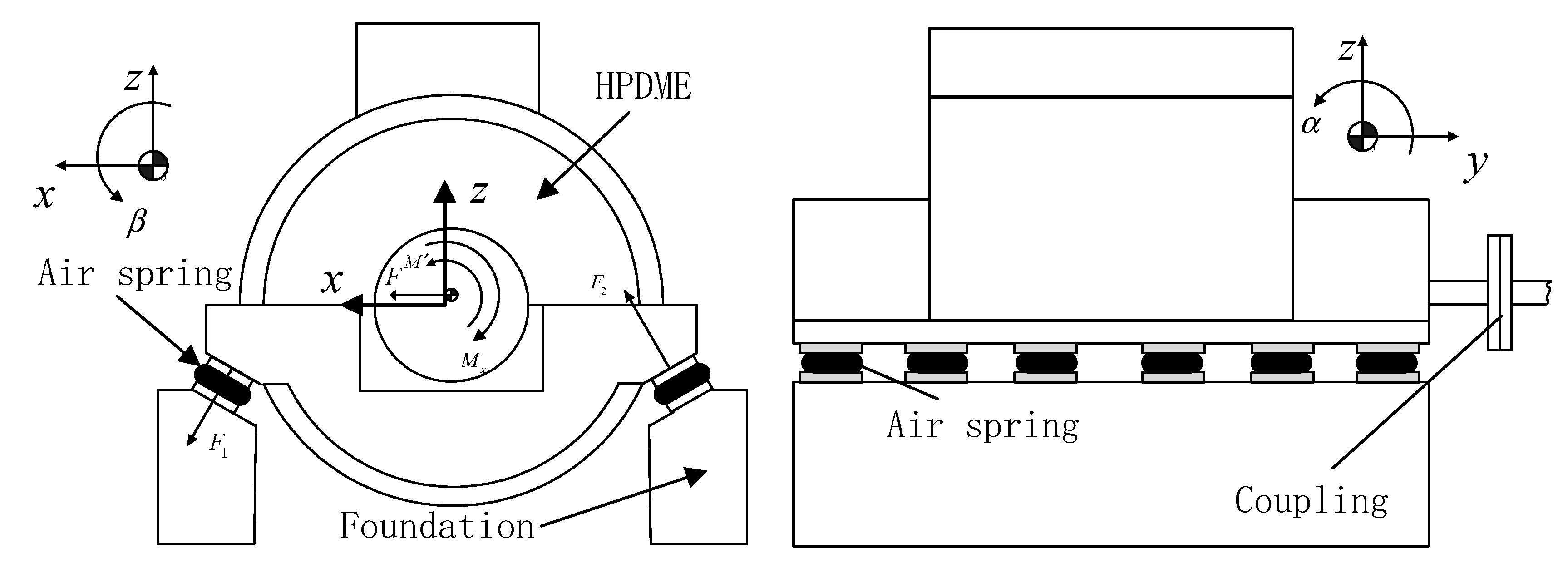
2.2. Mechanical Analysis

2.2.1. Mechanical Influence Analysis of Output Torque

The center of gravity, the horizontal offset, and the self-rotation angle vary with the output torque. For HPDME-ASVIS, the misalignment effect caused by the output torque is far greater than that caused by other disturbances [11]. Ignoring the angular stiffness of the air springs and the stiffness of the coupling [38], the horizontal offset and self-rotation angle caused by the output torque M x are [11]
x c = i = 1 n a x i k 13 i + i = 1 n k 1 i a z c a z i = 1 n a x i k 13 i 2 + i = 1 n k 1 i i = 1 n a x i 2 k 3 i M x β = i = 1 n k 1 i i = 1 n a x i k 13 i 2 + i = 1 n k 1 i i = 1 n a x i 2 k 3 i M x
where M x is output torque, a i c ( i = x , y , z ) are the coordinates of the coupling center point in the global coordinate, a x i , a y i , a z are the coordinates of the i# air spring in the global coordinate system, k 1 i , k 2 i , k 3 i , k 13 i are the stiffness of the i# air spring in the directions of the global coordinate, which can be expressed as
k 1 i = k p i cos 2 θ + k r i sin 2 θ k 2 i = k q i k 3 i = k p i sin 2 θ + k r i cos 2 θ k 13 i = k 31 i = sgn a x i k p i k r i sin θ cos θ
where k p i , k q i , k r i are the lateral, lateral, and vertical stiffness of the i# air spring, θ is the inclination angle of the air springs and sgn a x i is the sign function of a x i (1 if a x i > 0 or −1 if a x i < 0 ).
Equation (5) shows a linear relationship between the output torque M x and the horizontal offset x c and the self-rotation angle β positively, so they are greatly affected in HPDME-ASVIS at high output torque running state.

2.2.2. Vertical Deformation Analysis of Air Springs

The air springs produce large vertical deformations due to the large self-rotation angle β caused by the high output torque M x . The displacement of the i# air spring is
x i = G i x g
where G i is the position transformation matrix of the i# air spring in the global coordinate system. Combining Equations (4) and (7), the vertical deformation of the i# air spring is
z i = z g + a y i α a x i β = z c a y c a y i α + a x c a x i β
Combining Equations (5) and (8), it can be analyzed that the high output torque M x directly leads to the large self-rotation angle β , which leads to large vertical deformation of the i# air spring.

2.2.3. Mechanical Influence Analysis of Additional Force

From Equation (5), to control the horizontal offset x c and the self-rotation angle β into the given control range, a torque M must be generated to offset the output torque M x . However, at the same time, an additional force F in the horizontal direction (or other direction) will be generated as shown in Figure 1 where F is the resultant force of F 1 and F 2 which was generated by each air spring vibration isolator. From Equations (3) and (4), the horizontal offset and self-rotation angle caused by the additional force F are
x c = i = 1 n k 1 i a z 2 a z a z c i = 1 n a x i k 13 i 2 a z a z c + i = 1 n a x i 2 k 3 i i = 1 n a x i k 13 i 2 + i = 1 n k 1 i i = 1 n a x i 2 k 3 i F β = i = 1 n a x i k 13 i i = 1 n k 1 i a z i = 1 n a x i k 13 i 2 + i = 1 n k 1 i i = 1 n a x i 2 k 3 i F
From Equations (5) and (9), it can be concluded that the mechanical influence of additional force is different from that of output torque. When eliminating the horizontal offset x c and the self-rotation angle β caused by the output torque M x , an additional force F will be generated inevitably to cause the variation of the horizontal offset x c and the self-rotation angle β .
To sum up, the alignment controllability of HPDME-ASVIS mainly focuses on offsetting the influence of output torque M x and additional force F , ensuring that the horizontal offset, self-rotation angle, and vertical deformation of the air springs move into the given control precision range. It needs to solve three problems. The first is how to establish the alignment control response method of HPDME-ASVIS. The second is how to establish the alignment controllable judgment model and analyze the alignment reconfigurability. The third is how to establish an autonomous control for HPDME-ASVIS through the soft constraints adjustment strategy.

3. Alignment Control Response Model

It is assumed that only one air spring is inflated/deflated each time. The equivalent force on the main engine for the k-th air pressure adjustment is [6]
F Δ δ p ( k ) = G i T sgn a x i Δ δ p i S e sin θ , 0 , Δ δ p i S e cos θ , 0 , 0 , 0 T
where i is the air spring serial number for k-th inflated/deflated, Δ δ p i is the air pressure variation of i-th air spring, θ is the inclination angle of the air springs, sgn ( a x i ) is the sign function of a x i (1 if a x i > 0 or −1 if a x i < 0 ), and S e is the effective load-bearing area of the air spring (all air springs have the same area).
Ignoring the effect of air pressure variation on the global stiffness matrix, the alignment control response for the k-th air pressure adjustment can be obtained as [6]
Δ x c k + 1 = G c K - 1 F Δ δ p k
In the first k times of inflation/deflation, it is assumed that the air pressure variation for each air spring is δ p k = [ δ p 1 , δ p 2 δ p n ] T . Summing Equation (10), the equivalent force on the main engine after k times air pressure adjustment can be obtained as
F δ p k = i = 1 k F Δ δ p i = N δ p k
where each column N represents the equivalent force of unit pressure variation of each air spring, which can be expressed as
N = G 1 T sgn a x 1 S e sin θ 0 S e cos θ 0 0 0 , , G n T sgn a x n S e sin θ 0 S e cos θ 0 0 0
Summing Equation (11), the variation of the alignment state after k times air pressure adjustment can be obtained as
j = 0 k Δ x c j + 1 = j = 0 k G c K - 1 F Δ δ p j = G c K - 1 j = 0 k F Δ δ p j
After k times of air pressure adjustment, the alignment state of the main engine is
x c k + 1 = x c 0 + j = 0 k Δ x c j + 1
where x c 0 is the initial alignment state. Substituting Equations (12) and (14) into Equation (15), the alignment state can be further expressed as
x c k + 1 = x c 0 + G c K - 1 N δ p k
Generally, axial deformation y c is not used as the alignment monitoring component and control objective [37]. From Equation (8), it can be analyzed that the larger the y-direction coordinate of the air spring, the larger the vertical deformation it is likely to produce. At the same time, the vertical deformation of the air spring is often limited by the vertical displacement at the four corners of the HPDEME-ASVIS, which can be monitored by the displacement sensor. Therefore, the alignment control vector and vertical displacement vector are
y = x c z c α β χ T = 1 0 0 0 0 0 0 0 1 0 0 0 0 0 0 1 0 0 0 0 0 0 1 0 0 0 0 0 0 1 x c y c z c α β χ = Cx c z = z 1 z 2 z 3 z 4 = 0 0 1 a y 1 a y c a x c a x 1 0 0 0 1 a y 2 a y c a x c a x 2 0 0 0 1 a y 3 a y c a x c a x 3 0 0 0 1 a y 4 a y c a x c a x 4 0 x c y c z c α β χ = Dx c
where a x i , a y i (i = 1, 2, 3, 4) are the x-coordinate and y-coordinate of the four corners in the global coordinate system.
Substituting Equation (16) into Equation (17), the alignment control vector and vertical displacement vector after k times air pressure adjustment can be further expressed as
y k + 1 = C x c 0 + C G c K - 1 N δ p k z k + 1 = D x c 0 + D G c K - 1 N δ p k
With Equation (18), the values of the alignment control vector and the vertical displacement vector can be predicted before k times air pressure adjustment.

4. Reconfigurability Judgment Analysis and Autonomous Control Method

4.1. Alignment Controllability Judgement Analysis

For the alignment control system, the air pressure variation vector δ p is regarded as the input vector. The vertical displacement vector z is regarded as the linear function of the input vector. The alignment control vector y is regarded as the output vector.
According to the literature [31], input constraints, input association constraints, and output constraints during the alignment control are
δ p m i n δ p δ p m a x z m i n z k + 1 = D x c 0 + D G c K - 1 N δ p k z m a x y m i n y y m a x
According to the literature [39], the boundary for each alignment control component and vertical displacement constraint is
y m a x = y m i n = x c max , z c max , α max , β max , χ max T 0 z m a x = z m i n = z max , z max , z max , z max T 0
The air pressure adjustment constraint boundary is
δ p m i n = P m i n p 0 = p min , p min , p min T p 0 δ p m a x = P m a x p 0 = p max , p max , p max T p 0
where p 0 is the initial air pressure distribution. The input constraint space, input interconnection constraint space, and output constraint space are defined as
P ( δ P ) = δ p = δ p 1 , δ p 2 δ p n T δ p m i n δ p δ p m a x P Z ( δ P ) = δ p = δ p 1 , δ p 2 δ p n T z m i n z k + 1 = D x c 0 + D G c K - 1 N δ p k z m a x P ( Y ) = y = x c , z c , α , β , χ T y m i n y y m a x
The input generation space is defined as
P Y ( δ P ) = δ p = δ p 1 , δ p 2 δ p n T y m i n y k + 1 = C x c 0 + C G c K - 1 N δ p k y m a x
Taking the two-dimensional domain as an example, the controllability analysis of the HPDME-ASVIS is equivalent to the analysis of the intersection between the convex polyhedron P ( δ P ) , P Z ( δ P ) and P Y ( δ P ) , as shown in Figure 2. If the system is controllable, the intersection is a nonempty set.
It is assumed assume that the air spring pressure variation, the alignment control vector, and the vertical deformation vector of the air spring are δ p s , y s , z s in steady state condition. Based on linear programming, the alignment controllability can also be defined as: “if there is a non-empty set of parameters δ p s , y s , and z s that makes the Equation (19) valid, the alignment controllability is true, which also means that the alignment system is controllable; otherwise, the alignment controllability is false, which also means that the alignment system is uncontrollable”.

4.2. Alignment Controllability Judgment Model

From the analysis in Section 2, output torque and additional force cannot be offset at the same time. It cannot simultaneously control the horizontal offset, the self-rotation angle, and the vertical deformation of the air spring within a high given control precision range. However, to ensure the safe and stable operation of the shaft system, it is acceptable to relax some constraints and even reduce some of the alignment control precision. Considering the mechanical properties of HPDME-ASVIS, the parameters of air pressure, horizontal offset, self-rotation angle, and vertical deformation can be regarded as soft constraints, of which the constraint boundaries can be expanded. The rest of the parameters are regarded as hard constraints, of which the constraint boundaries are not allowed to adjust. By expanding the boundary of some constraints, the alignment system can be controlled by decreasing control precision. At this time, the control objectives are
P min P 0 ε p min , ε p min , , ε p min T δ p p max P 0 + ε p max , ε p max , , ε p max T z min ε z , ε z , ε z , ε z T z z max + ε z , ε z , ε z , ε z T y min ε x c , 0 , 0 , ε β , 0 T y y max + ε x c , 0 , 0 , ε β , 0 T s . t . { 0 ε p min ε p min max ; 0 ε p max ε p max max 0 ε z ε z max , 0 ε x c ε x c max ; 0 ε β ε β max
where ε p min , ε p max , ε x c , ε β , ε z is the adjustment amount of the boundary of each soft constraint, ε p min max , ε p max max , ε x c max , ε β max , ε z max is the maximum value of each corresponding acceptable adjustment amount.

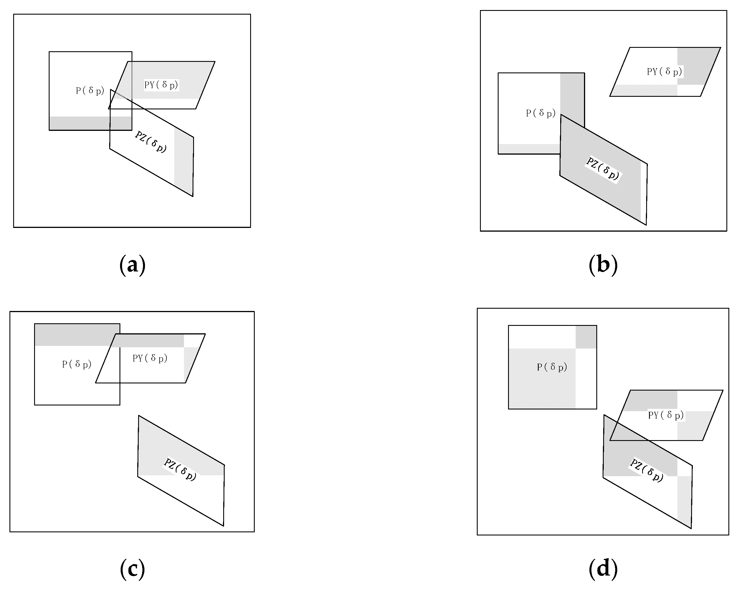
4.2.1. Alignment Controllability Judgment Model under Hard Constraints

For hard constraints conditions, all constraint boundaries are not allowed to adjust. It means that ε p min , ε p max , ε x c , ε β and ε z are all zero in Equation (24), which is equivalent to ε p min max , ε p max max , ε x c max , ε β max and ε z max being zero. Therefore, the controllable under hard constraints can be judged by solving a linear programming problem (LP)
s . t . V = min c T ε p min , ε p max , ε x c , ε β , ε z T , c T = 1 , 1 , 1 , 1 , 1 { P min ε p min , ε p min , , ε p min T P 0 δ p p max + ε p max , ε p max , , ε p max T P 0 y min ε x c , 0 , 0 , ε β , 0 T y = Cx c 0 + CG c K 1 N δ p k y max + ε x c , 0 , 0 , ε β , 0 T z min ε z , ε z , ε z , ε z T z = Dx c 0 + DG c K 1 N δ p k z max + ε z , ε z , ε z , ε z T 0 ε p min , ε p max , ε x c , ε β , ε z T
The judgment condition of alignment controllability under hard constraints is ε p min , ε p max , ε x c , ε β , ε z = 0 , corresponding to V = 0 ; otherwise V 0 , the alignment system under hard constraints is uncontrollable. It is noteworthy that it becomes a none constrained condition when ε p min , ε p max , ε x c , ε β , ε z .

4.2.2. Alignment Controllability Judgment Model under Soft Constraints

If the alignment system under hard constraints is judged as uncontrollable ( V 0 ), it is necessary to expand the boundary of some constraints autonomously, which is known as a control method under soft constraints. For the alignment control, the soft constraints can include air pressure, horizontal offset, self-angle, and vertical deformation of air springs. At the same time, it is fact that the soft constraints have upper and lower boundaries which perform the minimum requirements to ensure running safety. Thus, it should judge whether or not the system can be controlled when soft constraints are at their worst condition (at the boundary of each soft constraint). The adjustment variation of soft constraints can be written as
{ P min s = P min ε p min max , ε p min max , , ε p min T , P max s = P max + ε p max max , ε p max max , , ε p max max T y min s = y min ε x c max , 0 , 0 , ε β max , 0 T , y min s = y min + ε x c max , 0 , 0 , ε β max , 0 T z min s = z min ε z max , ε z max , ε z max , ε z max T , z min s = z min + ε z max , ε z max , ε z max , ε z max T
Similar to Equation (25), the alignment controllability under soft constraints can be judged by solving a linear programming problem (LP).
s . t . V = min c T ε p min , ε p max , ε x c , ε β , ε z T , c T = 1 , 1 , 1 , 1 , 1 { P min s ε p min , ε p min , , ε p min T P 0 δ p P max s + ε p max , ε p max , , ε p max T P 0 y min s ε x c , 0 , 0 , ε β , 0 T y = Cx c 0 + CG c K 1 N δ p k y max + ε x c , 0 , 0 , ε β , 0 T z min s ε z , ε z , ε z , ε z T z = Dx c 0 + DG c K 1 N δ p k z min s + ε z , ε z , ε z , ε z T 0 ε p min , ε p max , ε x c , ε β , ε z T
Combining Equations (26) and (27), the judgment condition of alignment controllability at the boundary of each soft constraint is still ε p min , ε p max , ε x c , ε β , ε z = 0 , corresponding V = 0 ; otherwise V > 0 , the alignment at the boundary of each soft constraint is uncontrollable. Compared with Equation (25), some constraints of Equation (27) have wider boundaries.
In practice, alignment control precision will decrease with the expansion of some soft constraints boundaries. When the system has alignment controllable under soft constraints, the smallest adjustment of each soft constraint boundary can be calculated as
ε p min , ε p max , ε x c , ε β , ε z = arg ε p min , ε p max , ε x c , ε β , ε z min h T ε p min , ε p max , ε x c , ε β , ε z T s . t . { P min ε p min , ε p min , , ε p min T P 0 δ p p max + ε p max , ε p max , , ε p max T P 0 y min ε x c , 0 , 0 , ε β , 0 T y = Cx c 0 + CG c K 1 N δ p k y max + ε x c , 0 , 0 , ε β , 0 T z min ε z , ε z , ε z , ε z T z = Dx c 0 + DG c K 1 N δ p k z max + ε z , ε z , ε z , ε z T 0 ε p min , ε p max , ε x c , ε β , ε z T
where h T = [ h p min , h p max , h x c , h β , h z ] is the weight coefficient vector. To perform dimensionless processing on different unit adjustments and reflect the user’s tolerance level for adjusting soft constraints boundaries, the weight coefficient vector is
h = H 1 ε p min max , 1 ε p max max , 1 ε x c max , 1 ε β max , 1 ε z max T = d i a g H p min , H p max , H x c , H β , H z 1 ε p min max , 1 ε p max max , 1 ε x c max , 1 ε β max , 1 ε z max T
where H i > 0 is the weight coefficient vector, which indicates the user’s tolerance level for adjusting soft constraints boundary. If H i < H j , it indicates that the user is more tolerant to adjust the boundary of ε i than to adjust the boundary of ε j . It is unacceptable to adjust the boundaries of this constraint when H i is extremely big. For the alignment control of HPDME-ASVIS, since the self-rotation angle has little influence on the deformation of the coupling, it is more acceptable to adjust the boundary of the self-rotation angle than the boundary of other adjustable parameters, so H i > H β .

4.3. Alignment Reconfigurability Analysis

Wang et al. [15] pointed out that three elements need to be considered when describing the actual reconfiguration capability of a spacecraft control system. They are constraints, reconfiguration methods, and reconfiguration goals, in which the reconfiguration methods include changing the spatial configuration and control algorithms. This paper only analyzes the alignment reconfigurability in the specific running situation of high output torque. So the reconfigurability of HPDME-ASVIS is described as:
  • When the alignment control system under hard constraints is judged as controllable, the state is classified as a fault-free state (F state). It can achieve full alignment control objectives.
  • When the alignment system under hard constraints is judged as uncontrollable but is judged as controllable under soft constraints, the state is classified as I alignment control fault state (I state). At this time, the alignment of control objectives can be achieved by changing the control algorithm, which is also called software adjustment, but the alignment control precision will decrease.
  • When the alignment system under hard and soft constraints is judged as uncontrollable, the state is classified as an II alignment control fault state (II state). At this time, the minimum safety goal cannot be achieved by changing the control algorithm. The emergency protection device should be enabled. The emergency protection device is rigidly connected with the HPDME-ASVIS through the hydraulic cylinder, whose mechanism has been described in the literature [2]. The system is supported in a rigid rather than the air spring vibration isolation system. The spatial configuration of HPDME-ASVIS is changed, which is also called hardware adjustment. The safety alignment goal is achieved by sacrificing the vibration isolation of the HPDME-ASVIS.
  • When the alignment system under hard and under soft constraints are judged as uncontrollable and the emergency protection device failure occurs, this state is classified as a III alignment control fault state (III state). At this time, the safety and stability of the device cannot be guaranteed. HPDME-ASVIS must be shut down to assure safety immediately.
The reconfigurability of the HPDME-ASVIS will be described in Table 1.
The HPDME-ASVIS has four reconfiguration stages. Combining Equations (25) and (27), the alignment FRD can be defined as
γ = 1.0 i f   V = 0 0.9 i f   V 0   a n d   V = 0 0.1 i f   V 0   a n d   V 0 0 o t h e r w i s e
where γ is artificially determined according to constraints and reconfiguration goal. Correspondingly, the SRR can be defined as:
r = γ
Combining Equations (28) and (29), the FRD of the I state( V 0 and V = 0 ) can be further expressed as
γ = 0.1 × 1 H p min , 1 H p max , 1 H x c , 1 H β , 1 H z 1 - ε p min ε p min max , 1 - ε p max ε p max max , 1 - ε x c ε x c max , 1 - ε β ε β max , 1 - ε z ε z max T 1 H p min + 1 H p max + 1 H x c + 1 H β + 1 H z + 0.9
It is noteworthy that it can be obtained γ = 1 from Equation (32) when ε p min , ε p max , ε x c , ε β , ε z = 0 which is the FRD value of the F state.

4.4. Alignment Autonomous Control Method

The flow chart of the alignment autonomous control can be seen in Figure 3.
Combining Equations (25)–(27), and (30), the alignment autonomous control method of HPDME-ASVIS can be designed as:
Step 1: the device displacement, rotational speed, air spring pressure, and other sensor signals are collected, and the initial alignment state is calculated;
Step 2: the alignment FRD is calculated by analyzing the reconfigurability.
Step 3: if γ = 1 go to Step 4; if γ = 0.9 go to Step 5; if γ = 0.1 go to Step 6; otherwise, HPDME-ASVIS must be shut down immediately.
Step 4: the alignment control method under hard constraint is executed until the alignment state reaches the given control precision range, end;
Step 5: by solving Equation (28), the smallest adjustment ε p min , ε p max , ε x c , ε β , ε z of each soft constraint boundary is obtained, and ε p min max , ε p max max , ε x c max , ε β max , ε z max in Equation (26) is replaced to modify the hard constraint boundary. The alignment control method based on a new constraint boundary is used to control the alignment state. Then go to Step 4 after modifying the hard constraint boundary;
Step 6: the emergency protection device is activated, end.
Comparing Figure 3a,b, the advantages of the autonomous control method can be seen intuitively. When the alignment system under hard constraints is judged as uncontrollable, the feasible solution to the problem can be broadened by modifying the control algorithm and expanding the hard constraint boundary automatically.

5. Experiment

5.1. Experiment Settings

To verify the mechanical analysis and autonomous control method proposed in this paper, experiments are carried out for a HPDME-ASVIS. The total weight of the HPDME-ASVIS is about 50 tons and the air spring with a load of 8 tons and a natural frequency of 5 Hz. HPDME-ASVIS is supported by 12 air springs with an inclined angle of 30°. The placement of air springs and sensors is shown in Figure 4.
In Figure 4b, 1#~4# are vertical displacement sensors, and 5#~7# are horizontal displacement sensors, which are used to monitor the alignment state of the HPDME-ASVIS. The compositions of HPDME-ASVIS are shown in Table 2.

5.2. Experiment Results

5.2.1. Mechanical Analysis Verification Experiment

To verify the analysis results obtained in Section 2.2, the running state of the HPDME-ASVIS is classed as five states: S1, S2, S3, S4, and S5. The output torque of the S1 state is 67.54 kN·m. The output torque of the S3 state is 109.14 kN·m. The output torque of the S5 state is 290.65 kN·m. The output torque of the S2 state is gradually increased from 67.54 kN·m to 109.14 kN·m(S1 to S3). The output torque of the S4 state is gradually increased from 109.14 kN·m to 290.65 kN·m(S3 to S5). The alignment control process under hard constraints is shown in Figure 5.
It can be seen in Figure 5:
(1) Under the condition of medium and low output torque (S1–S3), HPDME-ASVIS can achieve high alignment control precision, and the vertical displacement of the air spring is also within the given control precision range;
(2) In the S4 state, with the increase of output torque, the self-rotation angle decreases gradually and goes out of given control precision;
(3) In the S5 state, the effective performance of the horizontal offset and the self-rotation angle is conflicting. The self-rotation angle is controlled into the given control precision range while the horizontal offset is controlled beyond range. At the same time, in the S5 state in Figure 5b, the values of the 1# and 2# vertical displacement also go beyond the given control precision range. In the S5 state in Figure 5c, the system state switches between 1 state and 3 state frequently (1 state represents normal operation, 3 state represents emergency protection), which shows that the air vibration isolation device frequently opens and closes the emergency protector device. At this time, the alignment control system falls into oscillation.
The experiment result confirms the mechanical analysis results in Section 2.2.

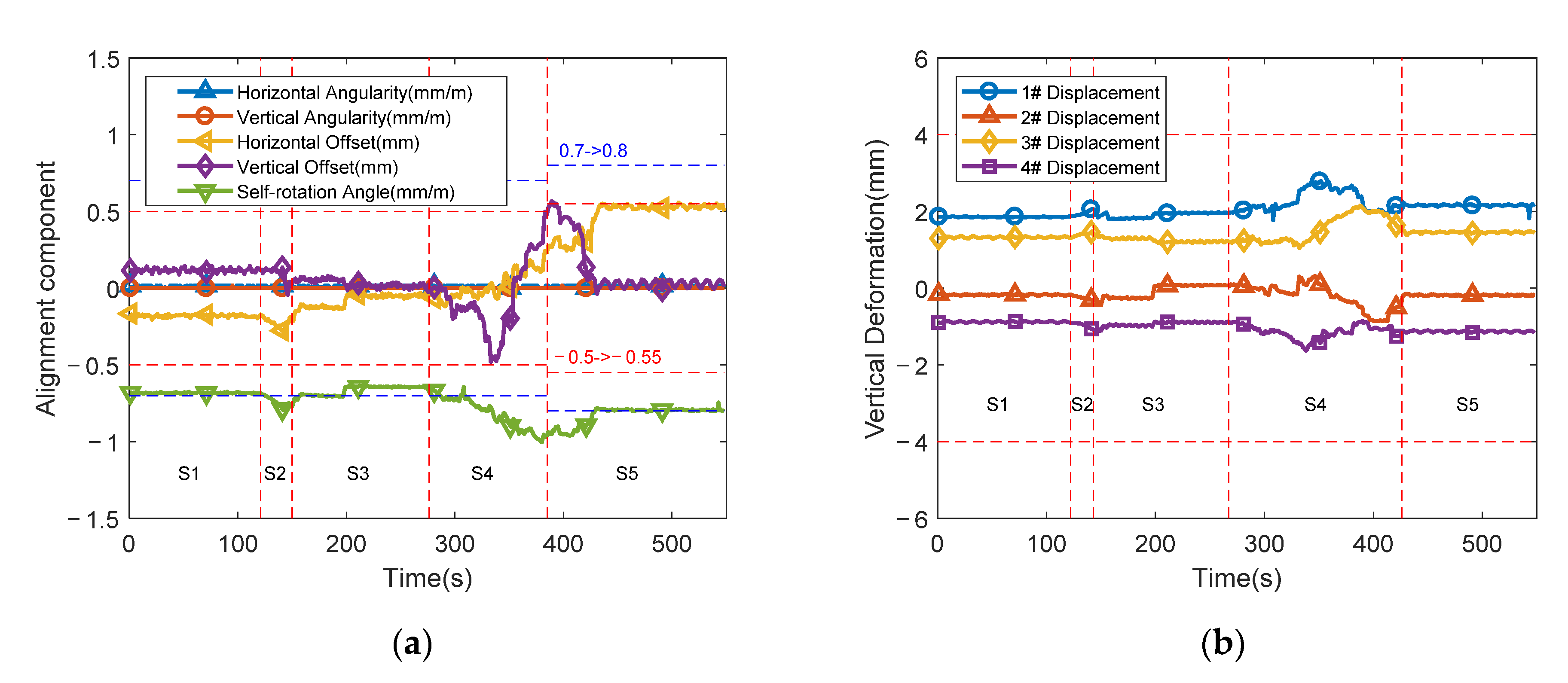
5.2.2. Validation Experiment of Alignment Autonomous Control Method

Under the same experimental conditions, the initial alignment target is the same, and the alignment autonomous control method is used to control the device. The alignment control process is shown in Figure 6. Since the initial target range of air pressure and vertical displacement is already very large, it is not desirable to adjust it, so it is acceptable to adjust the target range of the self-rotation angle and horizontal offset. H p min , H p max , and H z are set to larger values, while H x c and H β are set to smaller values.
It can be seen from Figure 6 that the air spring vibration isolation device can normally complete the alignment control not only under medium and low output torque conditions but also in high output torque conditions. The main experimental results are:
(1) From the trend of Figure 6a, with the increase of output torque, horizontal offset and self-rotation angle sharply decrease in the S2 state, in which the self-rotation angle goes beyond the given control precision range. In the S3 state, the self-rotation angle is controlled within the given control precision range immediately. As the output torque increases further (S4 state), the self-rotation angle goes beyond the given control precision range greatly.
(2) In the S5 state, the system is judged uncontrollable under hard constraints. The system state is classed as an II alignment control fault state under soft constraints. The smallest adjustment of self-rotation angle boundary and horizontal offset boundary is calculated, in which the boundary of self-rotation angle is adjusted from ±0.7 mm/m to ±0.8 mm/m and the boundary of horizontal is adjusted from ±0.5 mm to ±0.55 mm. The alignment state can then be controlled to the given accuracy range under soft constraints. Meanwhile, all vertical displacements are within the given control precision range in Figure 6b all the time.
The experiment result confirms that the autonomous control is effective in HPDME-ASVIS.

6. Conclusions and Future Works

Aiming at the special running situation of high power and high output torque in HPDME-ASVIS, the alignment controllability under hard constraints and soft constraints is analyzed by solving the linear programming problem. The alignment reconfigurability analysis is described based on alignment controllability. Then the alignment autonomous control is designed, which uses the combination of software and hardware to reconfigure the alignment control fault state. The experimental results verify the effectiveness of the method. The main conclusions of this paper are as follows:
(1) By studying the control response model, the values of the alignment control vector and the vertical displacement vector can be predicted before k times of the air spring inflation/deflation actual.
(2) By solving the linear programming problem, the alignment controllability judgment model under hard constraints and soft constraints are constructed, respectively.
(3) Based on the controllability judgment model, the alignment reconfigurability of HPDME-ASVIS is analyzed. Furthermore, an alignment of autonomous control is proposed. By changing the control algorithm, the I alignment control fault state is reconfigured. By changing the spatial configuration, the II alignment control fault state is reconfigured.
(4) The experiment results confirm that there is a conflict between horizontal offset and the self-rotation angle. The alignment autonomous control can accurately judge the controllability of the system and reconfigure the I alignment control fault state.
The disadvantage of this paper is that it does not consider the quantitative calculation of the reconfigurability when each component of the device fails. The next step will be to study the quantitative calculation of reconfigurability when each component of the device fails.

Author Contributions

Conceptualization, W.-J.B. and L.S.; methodology, W.-J.B., and L.S.; resources, W.-J.B. and L.S.; data curation, J.-W.C.; writing—original draft preparation, J.-W.C. All authors have read and agreed to the published version of the manuscript.

Funding

This research was funded by Key Laboratory of Fund Project of China, grant number 9140C280301.

Institutional Review Board Statement

Not applicable.

Informed Consent Statement

Not applicable.

Acknowledgments

The authors are grateful to the anonymous reviewers and the editor for their critical and constructive comments on this paper.

Conflicts of Interest

The authors declare no conflict of interest.

Nomenclature

F additional force generated by each air spring vibration isolator M the mass matrix of HPDME-ASVIS
f the external force vector exerted on HPDME-ASVIS M x output torque
p 0 the initial air pressure distribution of the air springs x c 0 the initial alignment state
δ p the air pressure variation of each air spring Δ δ p i the air pressure variation of i-th air spring
G c the position transformation matrix of the coupling center point in the global coordinate system
G i the position transformation matrix of the i# air spring in the global coordinate system
δ p s , y s , z s the air spring pressure variation, the alignment control vector, and the vertical deformation vector of the air spring in steady state condition
ε p min , ε p max , ε x c , ε β , ε z the adjustment amount of the boundary of each soft constraint
ε p min max , ε p max max , ε x c max , ε β max , ε z max the maximum value of each corresponding acceptable adjustment amount

References

  1. Shi, L.; He, L.; Bu, W.J.; Xu, W. Response characteristic analysis and alignment control algorithm for a main engine air suspension system. J. Vib. Shock 2012, 31, 136–139. [Google Scholar]
  2. He, L.; Xu, W.; Bu, W.J.; Shi, L. Dynamic analysis and design of air spring mounting system for marine propulsion system. J. Sound Vib. 2014, 333, 4912–4929. [Google Scholar] [CrossRef]
  3. Hujare, D.P.; Karnik, M.G. Vibration responses of parallel misalignment in Al shaft rotor bearing system with rigid coupling. Mater. Today Proc. 2018, 5, 23863–23871. [Google Scholar] [CrossRef]
  4. Patel, T.H.; Darpe, A.K. Vibration response of misaligned rotors. J. Sound Vib. 2009, 325, 609–628. [Google Scholar] [CrossRef]
  5. Bu, W.J.; He, L.; Shi, L.; Zhao, Y.L. Output shaft alignment attitude real time monitoring for a marine main engine air mounting system. J. Vib. Shock 2009, 28, 210–217. [Google Scholar]
  6. Xu, W.; He, L.; Shi, L. Alignment disturbance control of an air-suspended main engine. J. Vib. Shock 2011, 30, 6–10. [Google Scholar]
  7. Bu, W.J.; He, L. Alignment control straegy for an air spring mounting system of marine propulsion engine. J. Vib. Shock 2012, 31, 112–115. [Google Scholar]
  8. Shi, L.; He, L.; Xu, W.; Bu, W.J. Alignment controllability of ship main engine air suspension system. J. Nav. Univ. Eng. 2011, 23, 27–30, 35. [Google Scholar]
  9. Bu, W.J.; He, L.; Shi, L. Alignment controllability of air spring vibration isolation system of a ship propulsion plant. J. Vib. Shock 2015, 34, 56–60. [Google Scholar]
  10. Zhao, X.Q.; Shuai, C.G.; Xu, W. On design of vibration-isolating system for high-power-density propulsion motor. J. Nav. Univ. Eng. 2019, 31, 31–35. [Google Scholar]
  11. Zhao, J.M.; Bu, W.J.; Shi, L.; Hu, Z. Stability Design of Air Vibration Isolation Device for a High Power Density Main Engine. Symmetry 2021, 13, 1244. [Google Scholar] [CrossRef]
  12. Gao, J.J. Ji Qi Gu Zhang Zhen Zhi Yu Zi Yu Hua; Higher Education Press Beijing: Beijing, China, 2012. (In Chinese) [Google Scholar]
  13. Li, Y.F.; Mi, J.; Huang, H.Z.; Xiao, N.C.; Zhu, S.P. System reliability modeling and assessment for solar array drive assembly based on bayesian networks. China Sci. 2012, 15, 986–991. [Google Scholar]
  14. Liu, C.; Wang, D. Reconfigurability Analysis Method for Spacecraft Autonomous Control. Math. Probl. Eng. 2014, 2014, 105–110. [Google Scholar]
  15. Wang, D.Y.; Tu, Y.Y.; Liu, C.R.; He, Y.Z.; Li, W.B. Connotation and Research of Reconfigurability for Spacecraft Control Systems: A Review. Acta Autom. Sin. 2017, 43, 1687–1702. [Google Scholar]
  16. Contreras, B.; Checa, N.D.; Aguilar, M.; Michcol, B.C.; Morales Lopez, F.E. Using a Realization Technique for System Reconfigurability Evaluation: Simulation Application on a DC Motor. In Proceedings of the 2011 IEEE Electronics, Robotics and Automotive Mechanics Conference, Cuernavaca, Mexico, 15–18 November 2011. [Google Scholar]
  17. Yang, Z.Y. Reconfigurability analysis for a class of linear hybrid systems. IFAC Proc. Vol. 2006, 39, 974–979. [Google Scholar] [CrossRef]
  18. Huang, C.K.; Yang, H.; Ren, W.J.; Jiang, B. Reconfigurability Analysis for a Class of Meta Aircraft Based on Interconnected System Method. Inf. Control 2018, 47, 290–296. [Google Scholar]
  19. Shaker, H.R.; Shaker, F. Control configuration selection for linear stochastic systems. J. Process Control 2014, 24, 146–151. [Google Scholar] [CrossRef]
  20. Du, G.X.; Quan, Q.; Yang, B.X.; Cai, K.Y. Controllability analysis for multirotor helicopter rotor degradation and failure. J. Guid. Control Dyn. 2015, 38, 978–985. [Google Scholar] [CrossRef]
  21. Vey, D.; Lunze, J. Structural reconfigurability analysis of multirotor UAVs after actuator failures. In Proceedings of the 2015 54th IEEE Conference on Decision and Control (CDC), Osaka, Japan, 15–18 December 2015. [Google Scholar]
  22. Ren, W.; Yang, H.; Jiang, B.; Staroswiecki, M. Fault recoverability analysis of switched nonlinear systems. Int. J. Syst. Sci. 2017, 48, 471–484. [Google Scholar] [CrossRef]
  23. Li, Y.F.; Zhu, S.P.; Li, J.; Peng, W.W.; Huang, H.Z. Uncertainty Analysis in Fatigue Life Prediction of Gas Turbine Blades Using Bayesian Inference. Int. J. Turbo Jet Engines 2015, 32, 319–324. [Google Scholar] [CrossRef]
  24. Brito, M.; Griffiths, G. A Bayesian approach for predicting risk of autonomous underwater vehicle loss during their missions. Reliab. Eng. Syst. Saf. 2016, 146, 55–67. [Google Scholar] [CrossRef]
  25. Mi, J.H.; Li, Y.F.; Yang, Y.J.; Peng, W.W.; Huang, H.Z. Reliability assessment of complex electromechanical systems under epistemic uncertainty. Reliab. Eng. Syst. Saf. 2016, 152, 1–15. [Google Scholar] [CrossRef]
  26. Li, X.Y.; Huang, H.Z.; Li, Y.F.; Xiong, X. A Markov Regenerative Process model for phased mission systems under internal degradation and external shocks. Reliab. Eng. Syst. Saf. 2021, 215, 107796. [Google Scholar] [CrossRef]
  27. Li, X.Y.; Huang, H.Z.; Li, Y.F. Reliability analysis of phased mission system with non-exponential and partially repairable components. Reliab. Eng. Syst. Saf. 2018, 175, 119–127. [Google Scholar] [CrossRef]
  28. Li, X.Y.; Huang, H.Z.; Li, Y.F.; Zio, E. Reliability assessment of multi-state phased mission system with non-repairable multi-state components. Appl. Math. Model. 2018, 61, 181–199. [Google Scholar] [CrossRef]
  29. Fu, G.Z.; Huang, H.Z.; Li, Y.F.; Zhou, J. An adaptive hybrid evolutionary algorithm and its application in aeroengine maintenance scheduling problem. Soft Comput. 2021, 25, 1–12. [Google Scholar] [CrossRef]
  30. Xi, Y.; Li, K. Feasibility Analysis of Constrained Multi-Objective MultiDegree-of-Freedom Optimization Control in Industrial Processes. Control Theory Appl. 1995, 12, 590–596. [Google Scholar]
  31. Luo, X.L.; Zhou, X.L.; Wang, S.B. Analysis of constrained optimal control with related constraints of input variables. Acta Autom. Sin. 2013, 39, 679–689. [Google Scholar] [CrossRef]
  32. Xi, Y.G.; Gu, H.Y. Feasibility analysis and soft constraints adjustment of CMMO. Acta Autom. Sin. 1998, 24, 727–732. [Google Scholar]
  33. Zhang, X.L.; Wang, S.B.; Luo, X.L. Feasibility analysis and constraints adjustment of constrained optimal control in chemical processes. CIESC J. 2011, 62, 2546–2554. [Google Scholar]
  34. Jiang, D.; Liu, X.J.; Kong, X.B. Soft Constrained MPC on Water Level Control in Steam Generator of a Nuclear Power Plant. Acta Autom. Sin. 2019, 45, 1111–1121. [Google Scholar] [CrossRef]
  35. Lu, S.; Lee, J.H.; You, F. Soft-constrained model predictive control based on data-driven distributionally robust optimization. AIChE J. 2020, 66, e16546. [Google Scholar] [CrossRef]
  36. Wabersich, K.P.; Krishnadas, R.; Zeilinger, M.N. A Soft Constrained MPC Formulation Enabling Learning From Trajectories With Constraint Violations. IEEE Control Syst. Lett. 2022, 6, 980–985. [Google Scholar] [CrossRef]
  37. Bu, W.J. Research on Alignment Detection and Control of Air Spring Vibration Isolation Technology for Ship Propulsion Main Engine; Naval University of Engineering: Wuhan, China, 2010. (In Chinese) [Google Scholar]
  38. Zhu, S.J.; Lou, J.J.; He, Q.W.; Wen, X.T. Vibration Theory and Vibration Isolation; National Defense Industry Press: Beijing, China, 2006. (In Chinese) [Google Scholar]
  39. Xu, W. Theoretical and Experimental Research on Air Spring Vibration Isolation Technology for Recommended Main Engines on Ships; Naval University of Engineering: Wuhan, China, 2010. (In Chinese) [Google Scholar]
Figure 1. Schematic diagram of HPDME-ASVIS.
Applsci 12 08211 g001
Figure 2. Controllability analysis based on geometric methods: (a) The three convex polyhedrons have a nonempty intersection, and the alignment is controllable; (b) Only P ( δ P ) and P Y ( δ P ) intersect, and the alignment is uncontrollable; (c) Only P ( δ P ) and P Z ( δ P ) intersect, and the alignment is not controllable; (d) Only P Y ( δ P ) and P Z ( δ P ) intersect, and the alignment is uncontrollable.
Applsci 12 08211 g002
Figure 3. Control flow chart: (a) The alignment control method under hard constraints; (b) The alignment autonomous control method.
Applsci 12 08211 g003
Figure 4. Experiment device: (a) Physical diagram of HPDME-ASVIS; (b) Human interaction of the control system.
Applsci 12 08211 g004
Figure 5. The alignment control process under hard constraints: (a) The control process of different alignment components; (b) The control process of vertical deformations of air springs at the four corners of the HPDEME-ASVIS; (c) The system state and the air spring number of inflation/deflation.
Applsci 12 08211 g005
Figure 6. The alignment control process using the alignment autonomous control method: (a) The change of the alignment component; (b) The change of the deformation of the vertical displacement sensor.
Applsci 12 08211 g006
Table 1. The reconfigurability description of HPDME-ASVIS.
ConditionConstraintsReconfiguration MethodReconfiguration GoalState
controllable under hard constraintshard constraints-full goalF
uncontrollable under hard constraints controllable under soft constraintssoft constraintssoftware adjustmentfull goalI
uncontrollable under hard constraints
uncontrollable under soft constraints
-hardware adjustmentsafety goalII
other cases--unreconfigurableIII
Table 2. The compositions table of HPDME-ASVIS.
DeviceAbbreviationNumberFunction
Industrial Personal ComputerIPC1collect sensor data, control the alignment state of HPDME-ASVIS, control the emergency protection device, carry out fault diagnosis and maintenance suggestions for HPDME-ASVIS, display data information, etc.
Displacement SensorDS7monitor the displacement
Air Spring-12support the weight of the HPDME-ASVIS and isolate vibration
Emergency Protection DeviceEPD6fix HPDME-ASVIS to limit excessive displacement in emergencies
Gas Source UnitGSU1control gas source.
Air Control UnitACU6control the inflation/deflation of air spring, adjust air pressure
Hydraulic Control UnitHCU1control emergency protector
Hydraulic LineHL1connect hydraulic source and protection
Air Line-1connect the gas source and air springs
Gas SourceGas1provide a clean and stable air source for the air spring
Hydraulic SourceHydraulic1provide stable hydraulic oil for the emergency protection device
Publisher’s Note: MDPI stays neutral with regard to jurisdictional claims in published maps and institutional affiliations.

