
Laboratory Testing and Theoretical Modeling of Deformations of Reinforced Soil Wall


Abstract
:1. Introduction
2. Methods
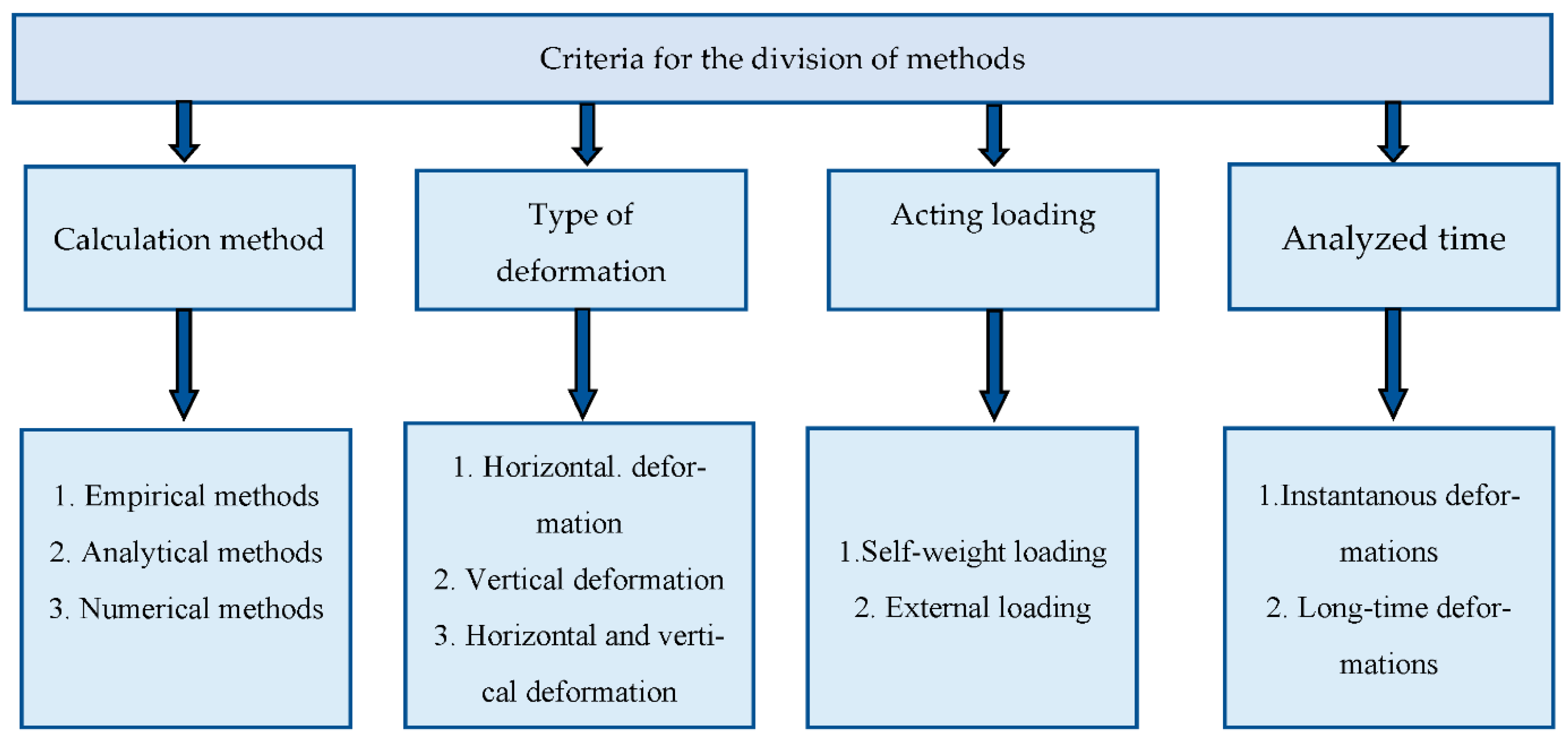
2.1. Background
2.2. Analytical Methods
2.3. Numerical Methods
3. Laboratory Model Tests
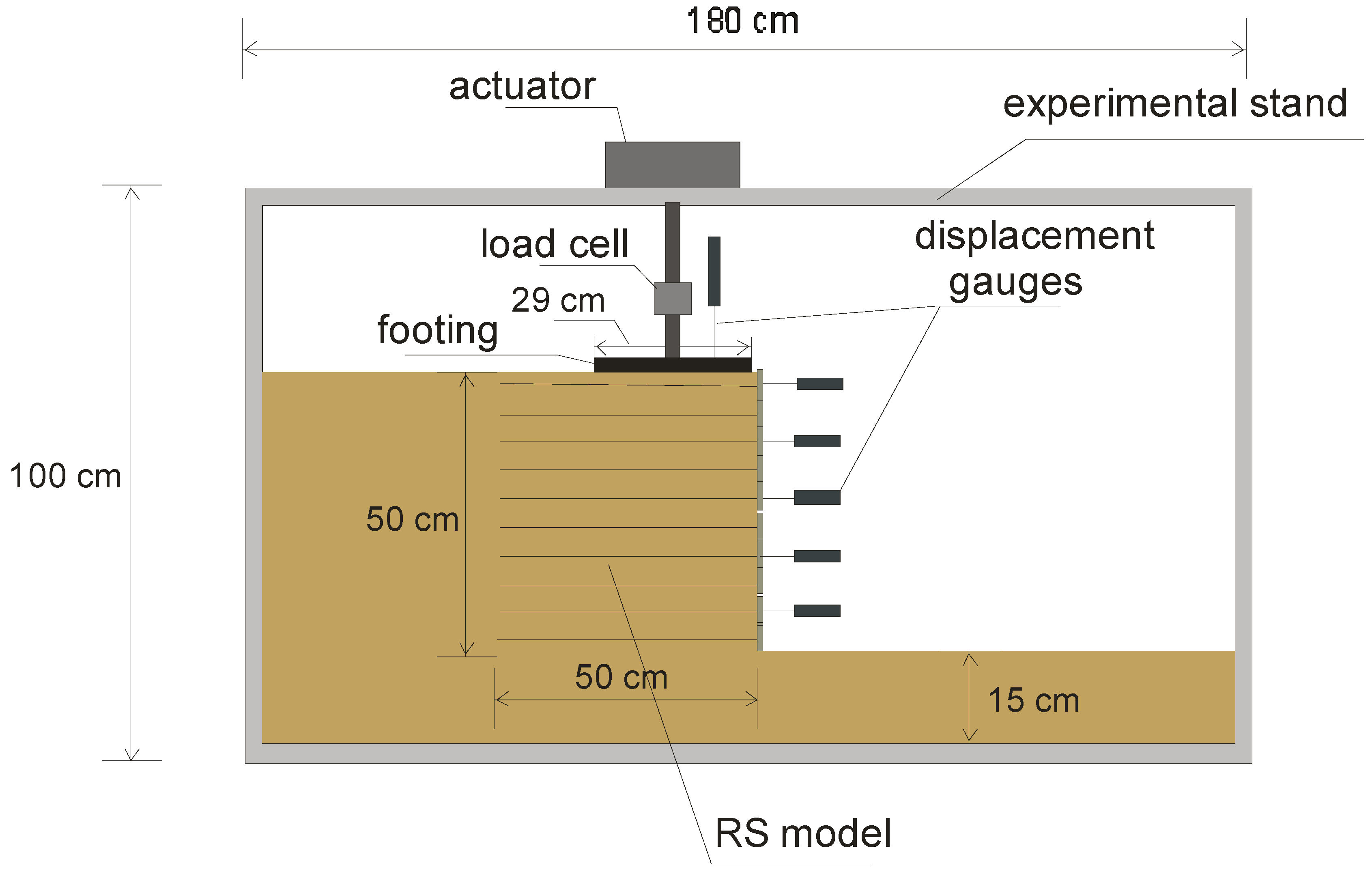
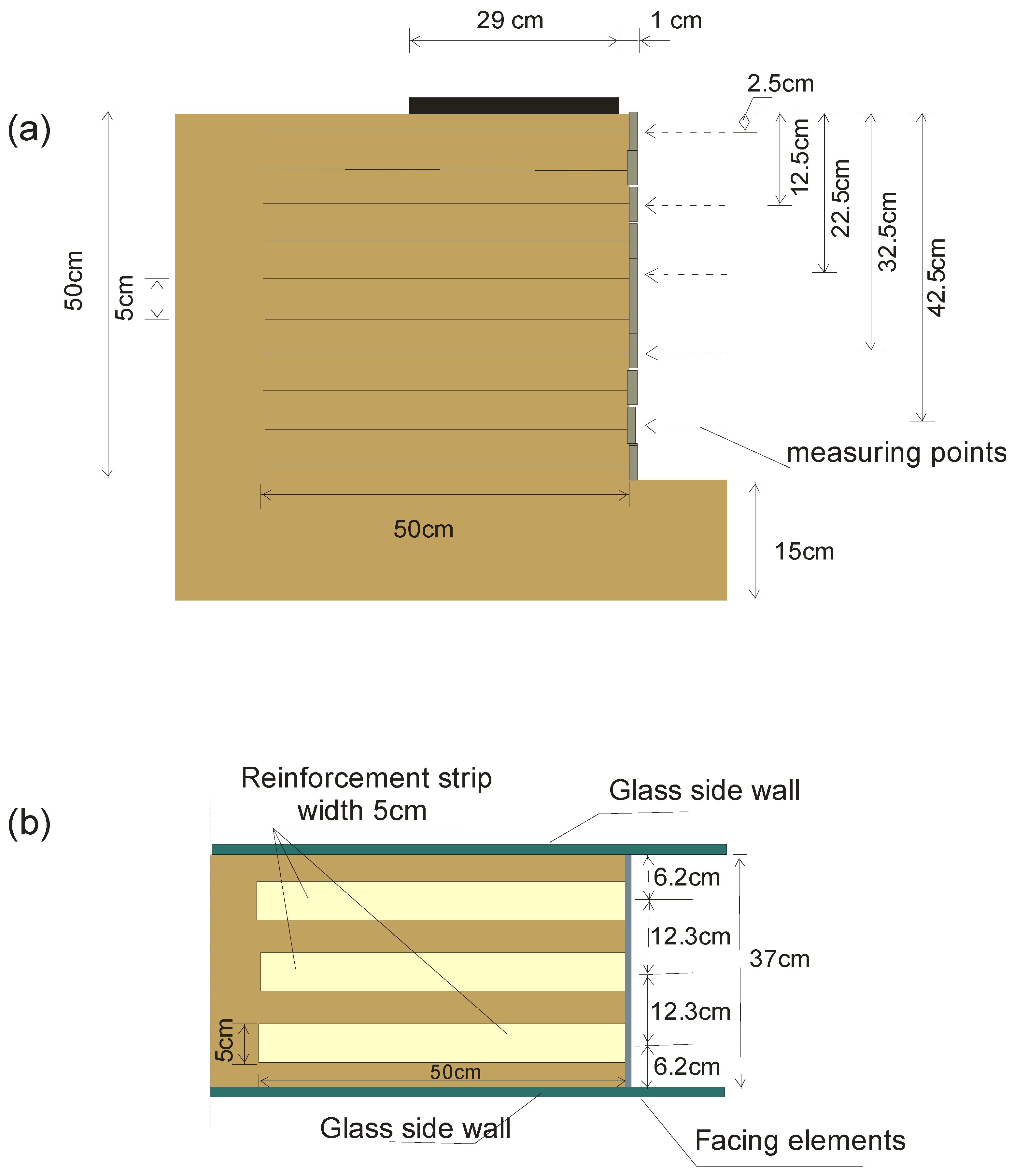
3.1. Experimental Set-Up
3.2. Characteristics of Materials Used in the Experimental Procedure
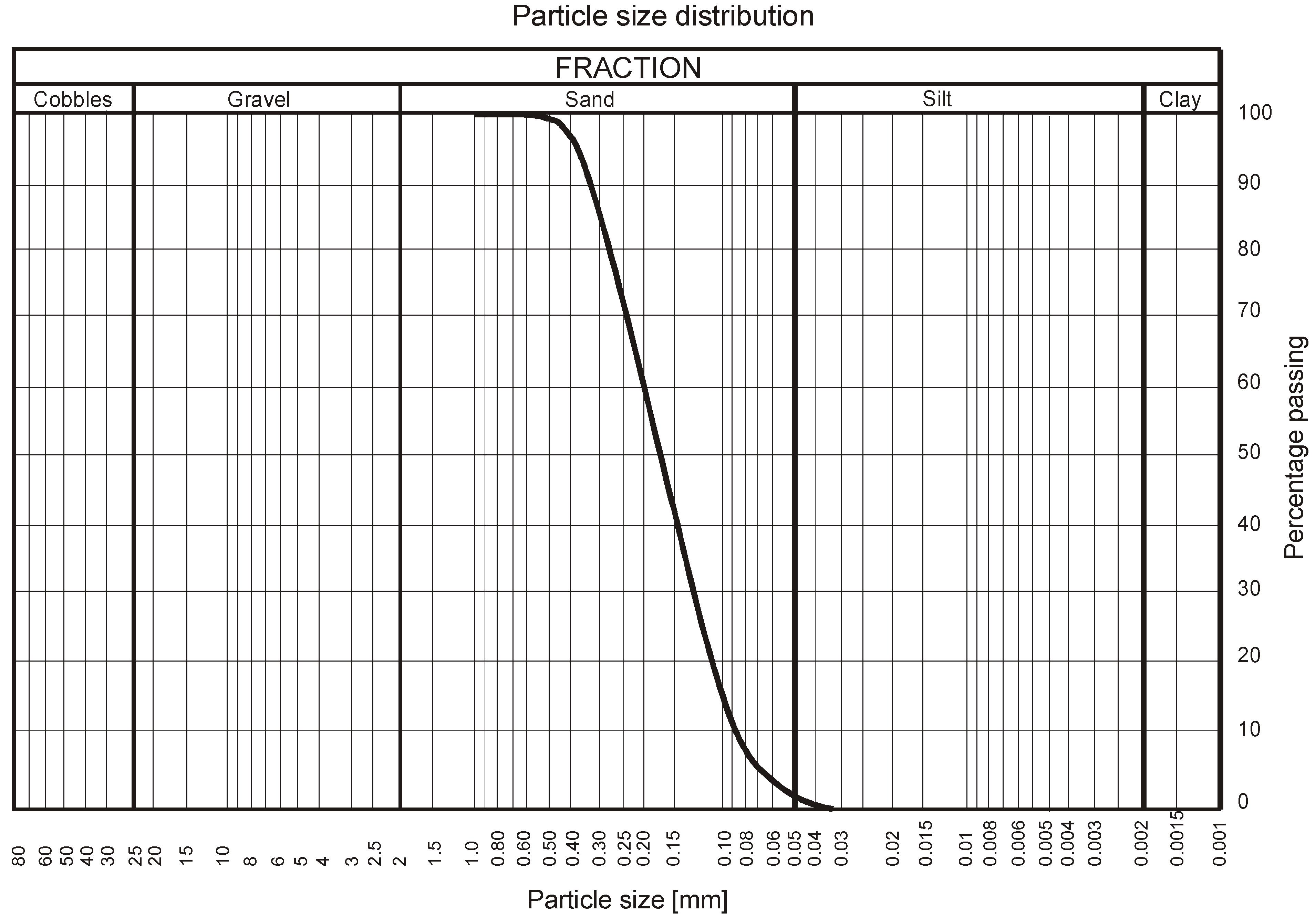
3.2.1. Backfill
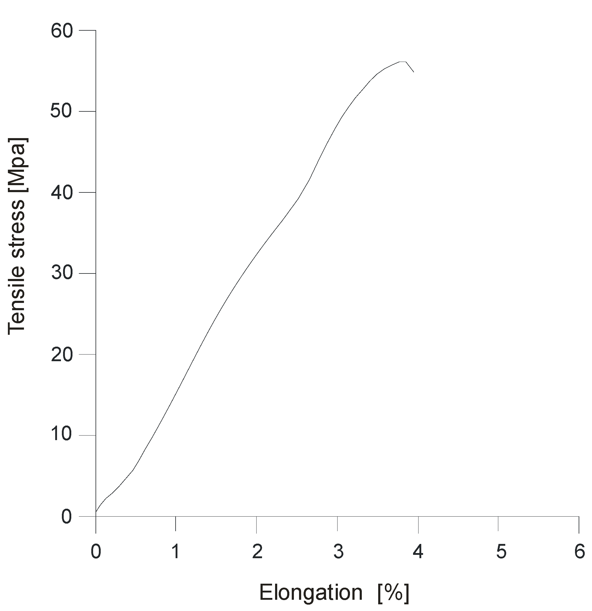
3.2.2. Reinforcement
3.2.3. Facing
3.3. Testing Procedure
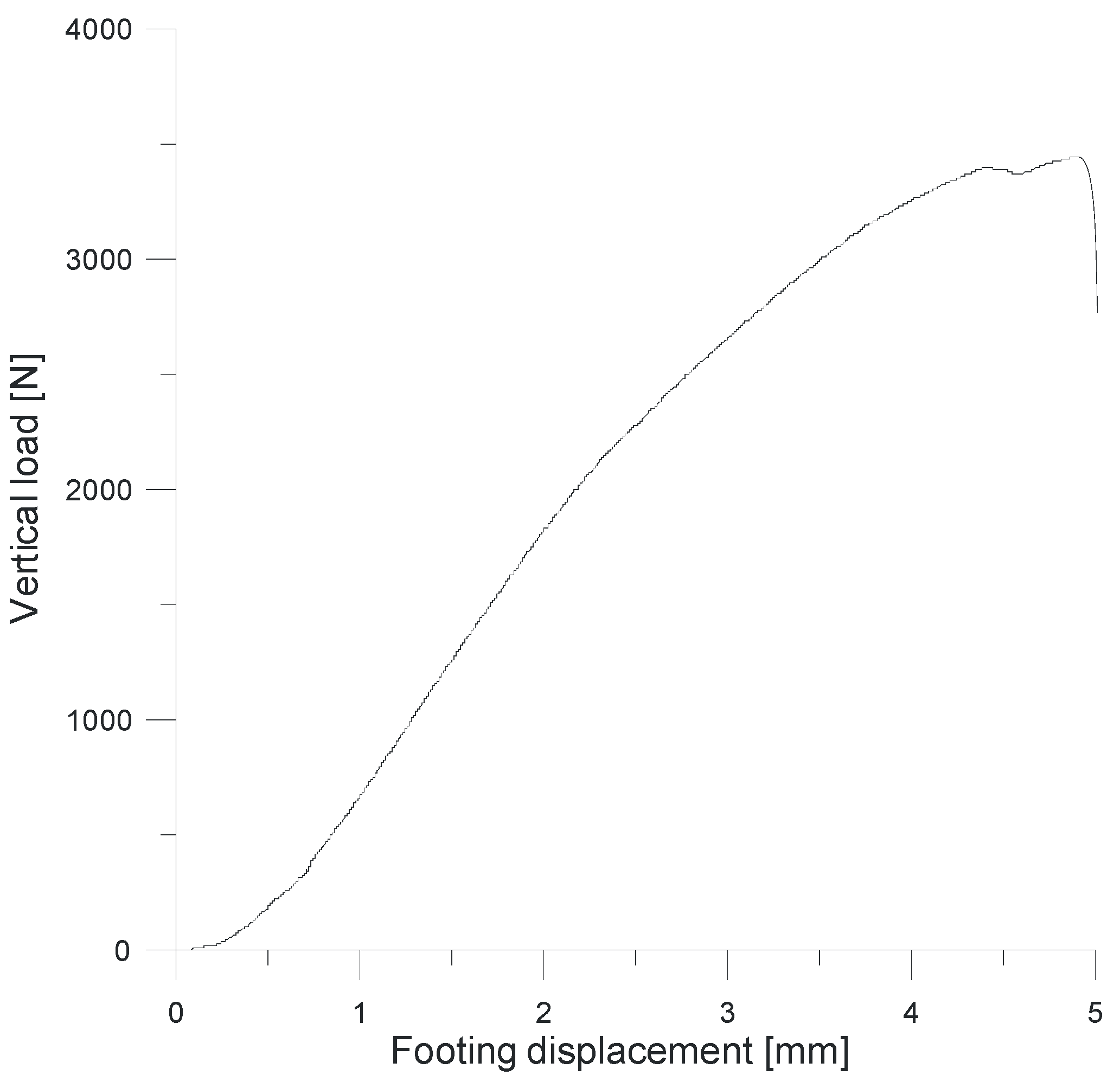
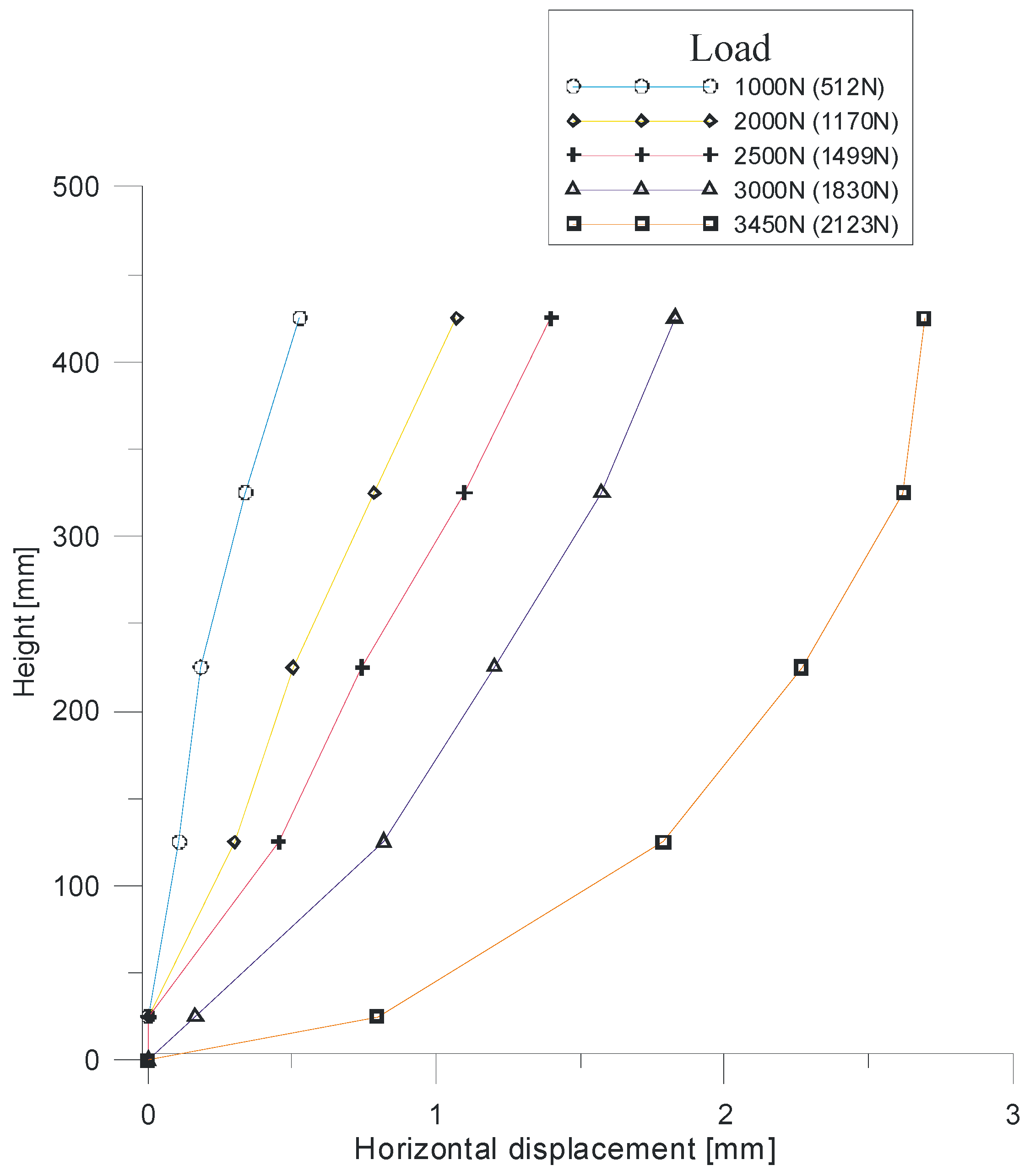
3.4. Experimental Results
3.5. The Effect of Friction between the Backfill and Side Walls of the Test Box
4. Theoretical Analysis: Analytical Approach
4.1. Basic Assumptions
- -
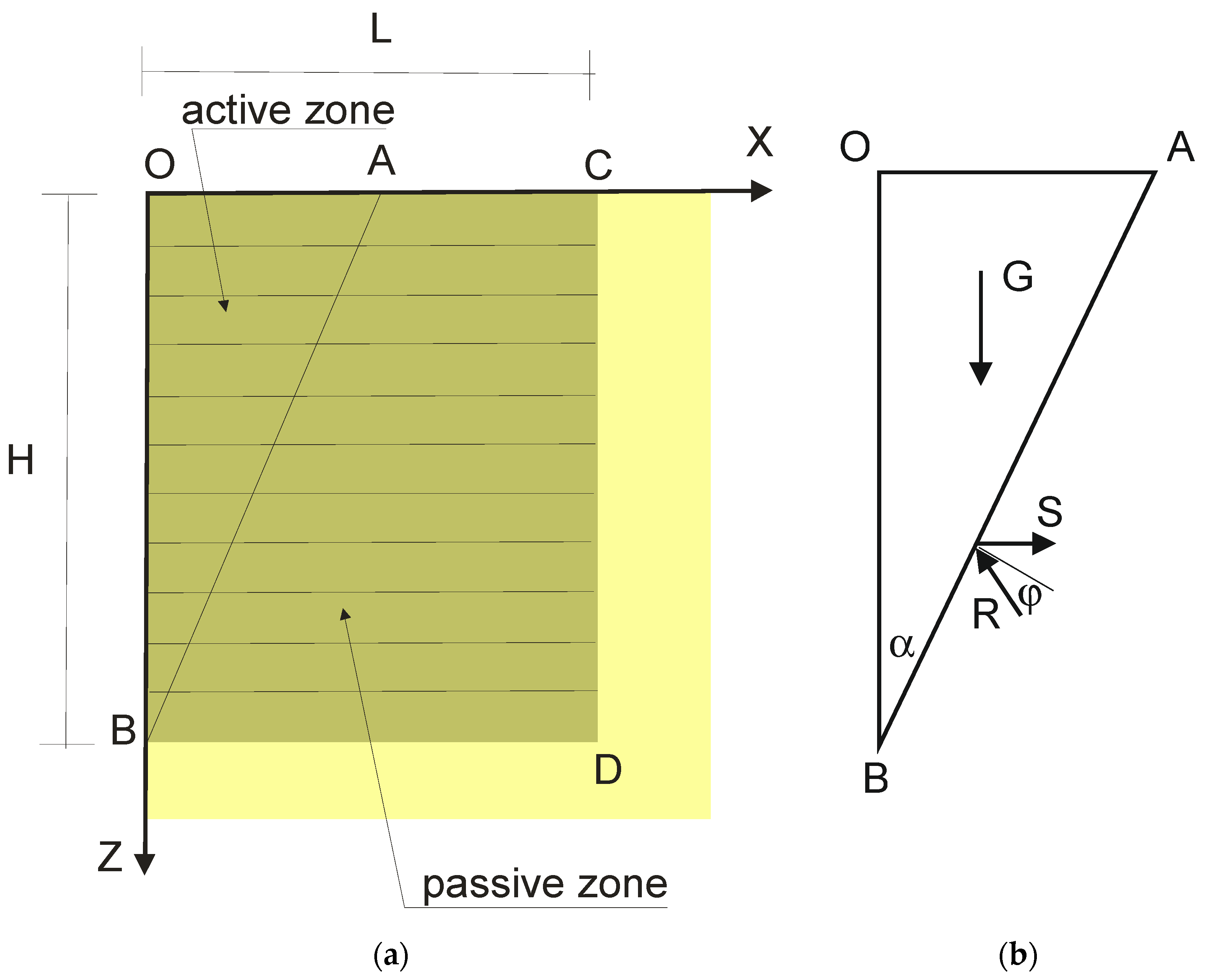
- The typical cross-section of the RS retaining wall was taken into consideration (Figure 11).
- -
- The soil was in a plastic state within the potential failure wedge ABO (active zone) and was rigid outside this area (passive zone).
- -
- Perfect bonding between the soil and the reinforcement was assumed (slippage of the reinforcement did not occur).
- -
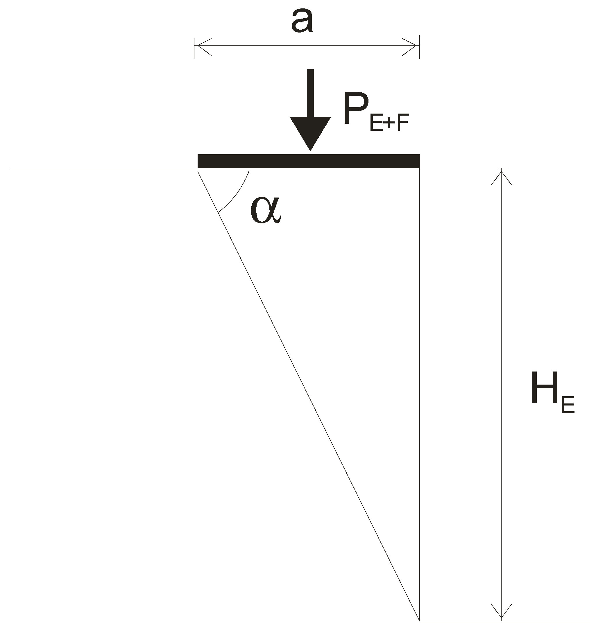
- The increasing external load (acting on the top of the structure) was, at first, smaller than, and eventually equal to, the collapse load.
- -
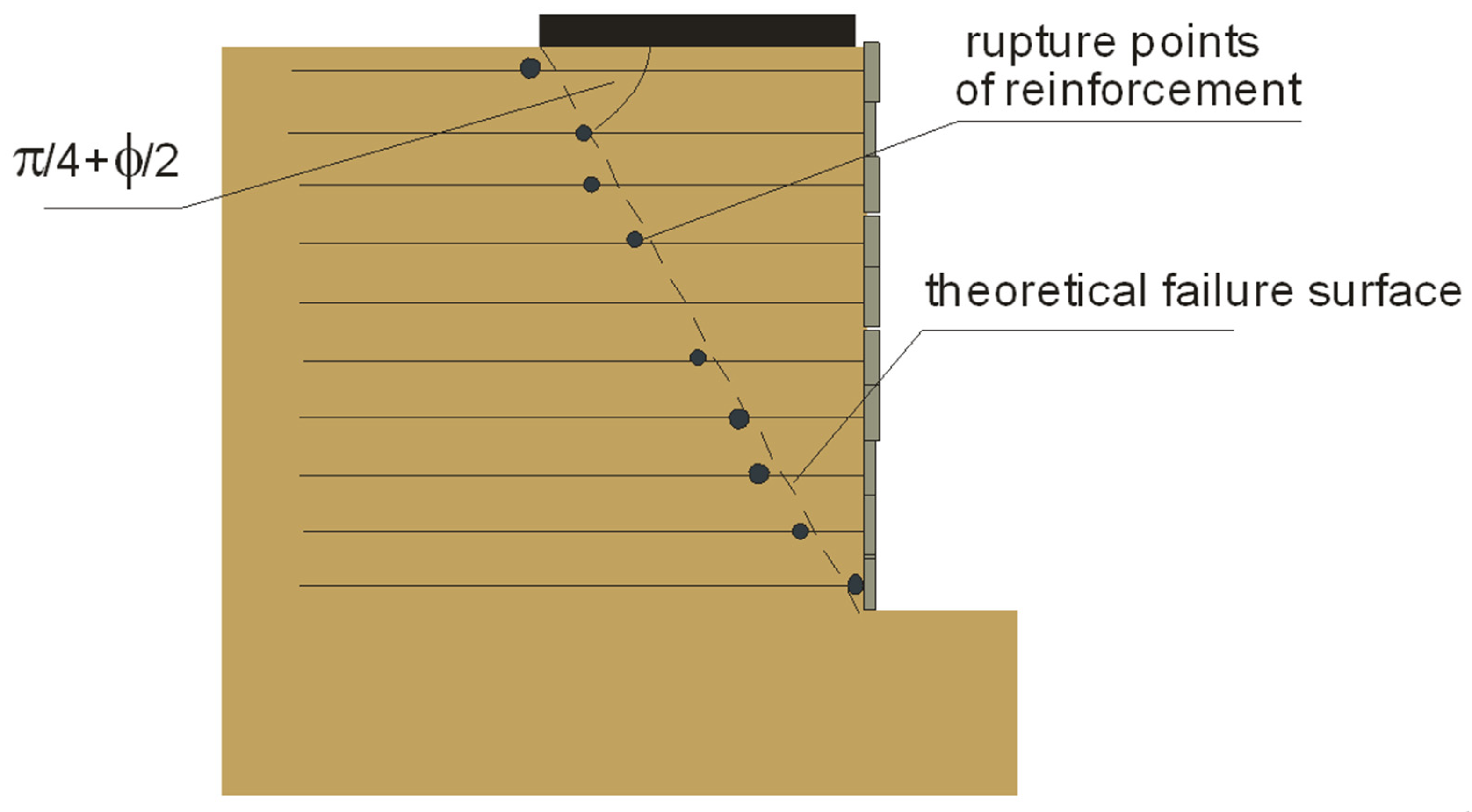
- The slippage of the wedge occurred along a planar failure surface that passed through the toe of the structure.
- -
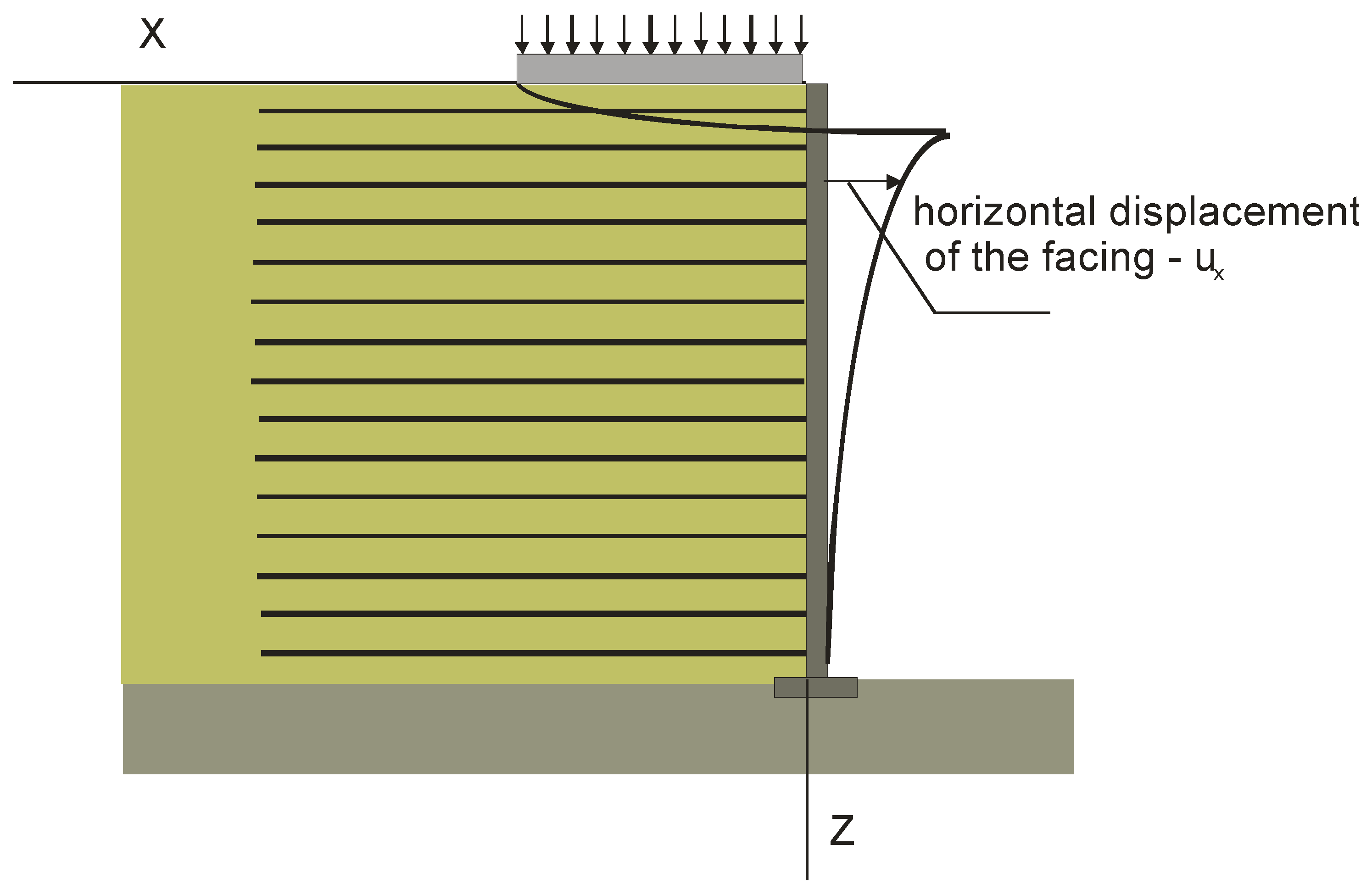
- The horizontal displacement (ux) of the facing of the model RS wall consisted of two parts:
4.2. Deformation in the Plastic Zone
4.3. Deformation in the Rigid Zone
- (1)
- (2)
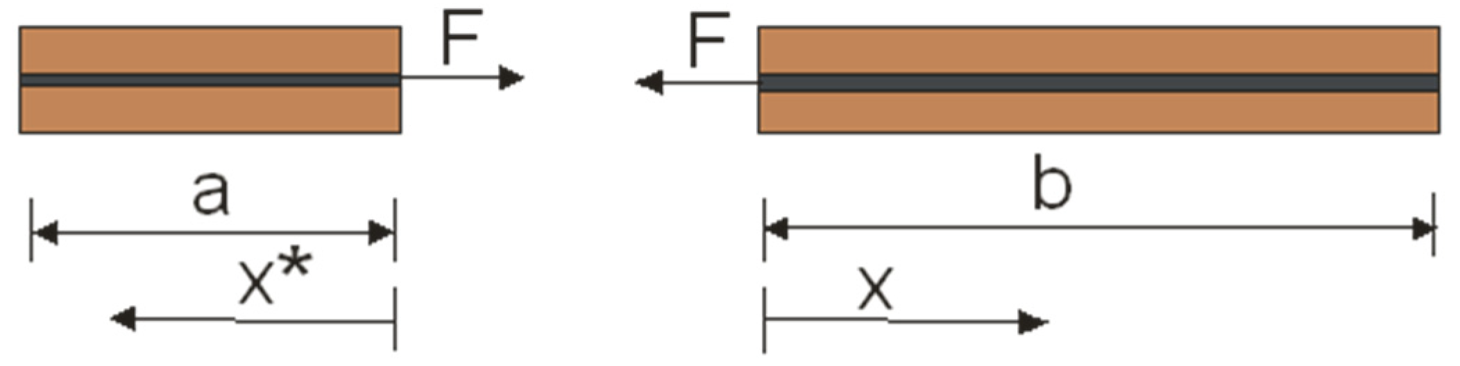
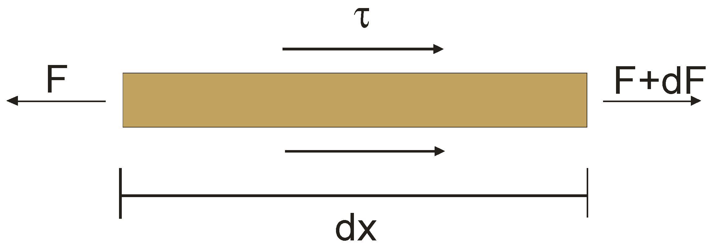
- The equation describing strain in the reinforcement strip:
- (3)
- The correlation between sheer stress (τ) and displacement (u):
- (4)
- The relationship between tensile strength and strain:
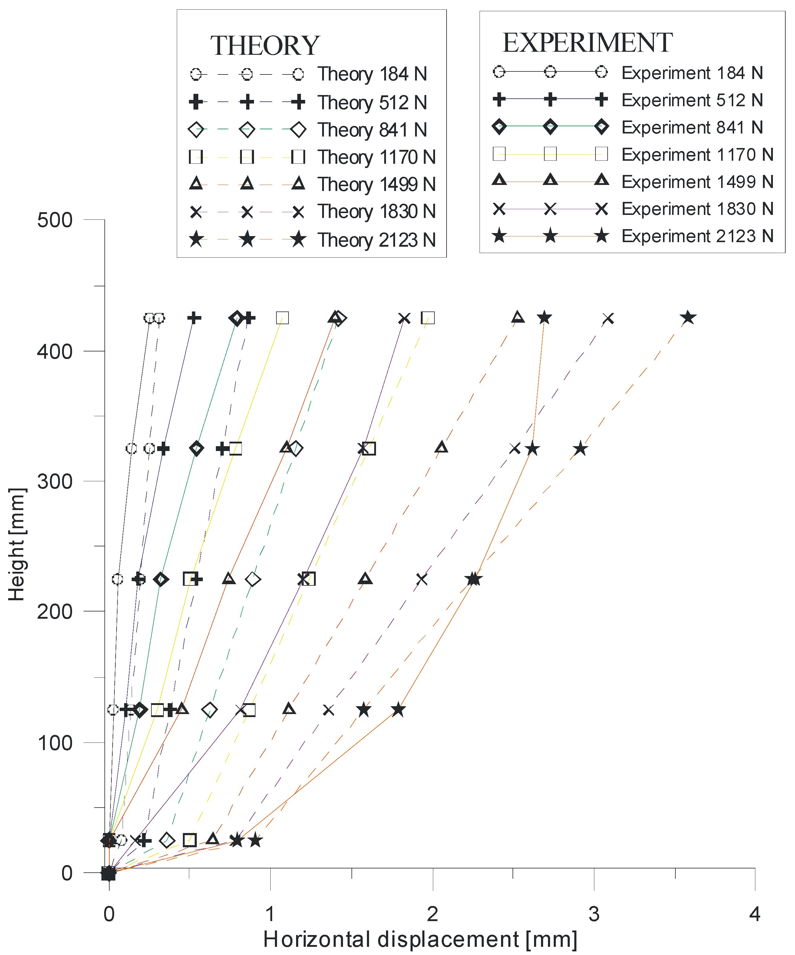
5. Comparison of Experimental and Theoretical Results
Verification of the Accurate Prediction of Experimental Results
6. Conclusions and Discussion
- -
- The experimental investigations of the reinforced soil wall made it possible to observe the magnitude and pattern of horizontal displacements under a sustained external load at the top of the model. The largest displacements occurred in the top layers of the RS structure and gradually decreased as the height of the model wall decreased. Our results were similar to those observed by other researchers [40,50,51].
- -
- An important and new insight that this paper introduces is the effect of friction between the backfill and the side walls of the test box on displacement. The effects of this factor tend to be omitted, or only generally discussed, by the authors of other experiments. However, our results show that friction has a significant impact on the value of external loading actually acting on the structure. In the analyzed case, even with the highest value of external loading on top of the structure, minimal reductions in the value of external loading actually acting on the structure were above 60% (Table 4). For example, the minimal reduction was 62.5% for an external load of 3450 N, 63.9% for an external load of 3000 N, and 66.8% for an external load of 2500 N. Therefore, the results clearly show that friction between the backfill and the side walls of the test box significantly influenced the horizontal displacement of the RS wall during the tests.
- -
- Our results suggest that the proposed analytical method can be used as an alternative approach to other analytical and numerical methods used to model the deformations of RS wall structures. Although far from exhaustive, the first verification of the accuracy of the IBW PAN method produced promising results.
- -
- The average difference between the recorded and calculated values of deformation did not exceed twenty five percent. Discrepancies between the model predictions and the experimental results may have resulted from inaccurate soil and reinforcement data.
- -
- The theoretical horizontal displacements that were analytically predicted for the model wall were larger than the experimental horizontal displacements. This tendency is correct and shows that the proposed analytical method can be used without breaching safety rules.
- -
- More complex constitutive soil models are investigated in the literature, but these models require input properties that are seldom available to design engineers. Moreover, greater accuracy in the predictions for more advanced models may not be assured [92]. Considering the accuracy of the results obtained, it should be stated that the proposed approach (and the models selected) are adequate from an engineering point of view.
- -
- The final results may be particularly useful when designing the reinforced soil structures used in transport engineering (e.g., bridge abutments), where the deformation limit values cannot be exceeded. In such cases, the key factor determining the permissible durability of the structures is the second limit state of use (related to the size of the deformations occurring).
Author Contributions
Funding
Institutional Review Board Statement
Informed Consent Statement
Data Availability Statement
Conflicts of Interest
References
- Allen, T.; Bathurst, R. Soil reinforcement loads in geosynthetic walls at working stress conditions. Geosynth. Int. 2002, 9, 525–566. [Google Scholar] [CrossRef]
- Lavasan, A.A.; Ghazavi, M. Behavior of closely spaced square and circular footings on reinforced sand. Soils Founduation 2012, 52, 160–167. [Google Scholar] [CrossRef] [Green Version]
- Mehrjardi, G.T.; Ghanbari, A.; Mehdizadeh, H. Experimental study on the behaviour of geogrid-reinforced slopes with respect to aggregate size. Geotext. Geomembr. 2016, 44, 862–871. [Google Scholar] [CrossRef]
- Sun, X.; Han, J.; Corey, R. Equivalent modulus of geogrid-stabilized granular base back-calculated using permanent deformation. J. Geotech. Geoenviron. Eng. 2017, 143, 06017012. [Google Scholar] [CrossRef]
- Weerasekara, L.; Hall, B.; Wijewickreme, D. A new approach for estimating internal stability of reinforced soil structures. Geosynth. Int. 2017, 24, 419–434. [Google Scholar] [CrossRef]
- Javankhoshdel, S.; Bathurst, R.J. Deterministic and probabilistic failure analysis of simple geosynthetic reinforced soil slopes. Geosynth. Int. 2017, 24, 14–29. [Google Scholar] [CrossRef]
- Mehrjardi, G.T.; Motarjemi, F. Interfacial properties of geocell-reinforced granular soils. Geotext. Geomembr. 2018, 46, 384–395. [Google Scholar] [CrossRef]
- Abd, A.H.; Utili, S. Design of geosynthetic-reinforced slopes in cohesive backfills. Geotext. Geomembr. 2017, 45, 627–641. [Google Scholar] [CrossRef]
- Wang, J.Q.; Zhang, L.L.; Xue, J.F. Load-settlement response of shallow square footings on geogrid-reinforced sand under cyclic loading. Geotext. Geomembr. 2018, 46, 586–596. [Google Scholar] [CrossRef]
- Xu, C.; Liang, C.; Shen, P. Experimental and theoretical studies on the ultimate bearing capacity of geogrid-reinforced sand. Geotext. Geomembr. 2019, 47, 417–428. [Google Scholar] [CrossRef]
- Rowe, R.K.; Yu, Y. Magnitude and significance of tensile strains in geomembrane landfill liners. Geotext. Geomembr. 2019, 47, 439–458. [Google Scholar] [CrossRef]
- Chehade, H.A.; Dias, D.; Sadek, M. Seismic analysis of geosynthetic- reinforced retaining wall in cohesive soils. Geotext. Geomembr. 2019, 47, 315–326. [Google Scholar] [CrossRef]
- Bildik, S.; Laman, M. Effect of geogrid reinforcement on soil—Structure–pipe interaction in terms of bearing capacity, settlement and stress distribution. Geotext. Geomembr. 2020, 48, 844–853. [Google Scholar] [CrossRef]
- Vidal, H. The principle of reinforced earth. Highw. Res. Rec. 1969, 1–16. Available online: https://onlinepubs.trb.org/Onlinepubs/hrr/1969/282/282-001.pdf (accessed on 14 May 2022).
- Lee, K.L.; Adams, B.D.; Vagneron, J.M.J. Reinforced earth retaining walls. J. Soil Mech. Found. Div. 1973, 99, 745–764. [Google Scholar] [CrossRef]
- Schlosser, F. Mechanically stabilized earth retaining structures in Europe. In Design and Performance of Earth Retaining Structures; Lambe, P., Hansen, L.A., Eds.; Geotechnical Special Publication; ASCE: Reston, VA, USA, 1990; pp. 347–378. [Google Scholar]
- Jones, C.J.F.B. Earth Reinforcement and Soil Structures (Butterworth’s Advanced Series in Geotechnical Engineering); Butterworth-Heinemann: London, UK, 1996; p. 379. [Google Scholar]
- Sawicki, A. Mechanics of Reinforced Soil; CRC Press: Brookfield, VT, USA, 2000. [Google Scholar]
- Karpurapu, R.; Bathurst, R.J. Behavior of geosynthetic reinforced soil retaining walls using the finite element analysis. Comput. Geotech. 1995, 17, 179–299. [Google Scholar] [CrossRef]
- Ho, S.K.; Rowe, R.K. Effect of wall geometry on the behaviour of reinforced soil walls. J. Geotext. Geomembr. 1996, 14, 521–541. [Google Scholar] [CrossRef]
- Rowe, R.K.; Ho, S.K. Continuous panel reinforced soil walls on rigid foundations. J. Geotech. Geoenviron. Eng. 1997, 123, 912–920. [Google Scholar] [CrossRef]
- Rowe, R.K.; Skinner, G.D. Numerical analysis of geosynthetic reinforced retaining wall constructed on a layered soil foundation. Geotext. Geomembr. 2001, 19, 387–412. [Google Scholar] [CrossRef]
- Ling, H.I.; Leshchinsky, D. Finite element parametric study of the behavior of segmental block reinforced-soil retaining walls. Geosynth. Int. 2003, 10, 77–94. [Google Scholar] [CrossRef]
- Hatami, K.; Bathurst, R.J. Development and verification of a numerical model for the analysis of geosynthethic-reinforced soil segmental walls under working stress conditions. Can. Geotech. J. 2005, 42, 1066–1085. [Google Scholar] [CrossRef]
- Hatami, K.; Bathurst, R.J. Numerical model for reinforced soil segmental walls under surcharge loading. J. Geotech. Geoenviron. Eng. 2006, 132, 673–684. [Google Scholar] [CrossRef]
- Skinner, G.D.; Rowe, R.K. Design and Behaviour of a Geosynthetic Reinforced Retaining Wall and Bridge Abutment on a Yielding Foundation. Geotext. Geomembr. 2005, 23, 234–260. [Google Scholar] [CrossRef]
- Chungsik, Y.; Kim, S.-B. Performance of a two-tier geosynthetic reinforced segmental retaining wall under a surcharge load: Full-scale load test and 3D finite element analysis. Geotext. Geomembr. 2008, 26, 460–472. [Google Scholar]
- Mendonça, A.; Lopes, M.; Pinho-Lopes, M. Construction and post-construction behaviour of a geogrid-reinforced steep slope. Geotech. Geol. Eng. 2003, 21, 129–147. [Google Scholar] [CrossRef]
- Bathurst, R.J.; Nernheim, A.; Walters, D.L.; Allen, T.M.; Burgess, P.; Saunders, D.D. Influence of reinforcement stiffness and compaction on the performance of four geosynthetic-reinforced soil walls. Geosynth. Int. 2009, 16, 43–59. [Google Scholar] [CrossRef]
- Kongkitkul, W.; Tatsuoka, F.; Kawahata, S.; Hirakawa, D.; Sugimoto, T.; Ito, M. Time histories of tensile force in geogrid arranged in two full-scale high walls. Geosynth. Int. 2010, 17, 12–32. [Google Scholar] [CrossRef]
- Horpibulsuk, S.; Suksiripattanapong, C.; Niramitkornburee, A.; Chinkulkijniwat, A.; Tangsutthinon, T. Performance of an earth wall stabilized with bearing reinforcements. Geotext. Geomembr. 2011, 29, 514–524. [Google Scholar] [CrossRef]
- Vieira, C.S.; Lopes, M.D.L.; Caldeira, L.M. Earth pressure coefficients for design of geosynthetic reinforced soil structures. Geotext. Geomembr. 2011, 29, 491–501. [Google Scholar] [CrossRef]
- Yang, G.; Liu, H.; Lv, P.; Zhang, B. Geogrid-reinforced lime-treated cohesive soil retaining wall: Case study and implications. Geotext. Geomembr. 2012, 35, 112–118. [Google Scholar] [CrossRef]
- Yang, G.; Liu, H.; Zhou, Y.T.; Xiong, B.L. Post-construction performance of a two-tiered geogrid reinforced soil wall backfilled with soil-rock mixture. Geotext. Geomembr. 2014, 42, 91–97. [Google Scholar] [CrossRef]
- Riccio, M.; Ehrlich, M.; Dias, D. Field monitoring and analyses of the response of a block-faced geogrid wall using fine-grained tropical soils. Geotext. Geomembr. 2014, 42, 127–138. [Google Scholar] [CrossRef]
- Benjamim, C.V.S.; Bueno, B.S.; Zornberg, J.G. Field monitoring evaluation of geotextile-reinforcedsoil-retaining walls. Geosynth. Int. 2007, 14, 100–118. [Google Scholar]
- Liu, J.; Liu, M.; Zhu, Z. Sand deformation around an uplift plate anchor. J. Geotech. Geoenviron. Eng. 2011, 138, 728–737. [Google Scholar] [CrossRef]
- Portelinha, F.H.M.; Zornberg, J.G.; Pimentel, V. Field performance of retaining walls reinforced with woven and nonwoven geotextiles. Geosynth. Int. 2014, 21, 270–284. [Google Scholar] [CrossRef] [Green Version]
- Scotland, I.; Dixon, N.; Frost, M.; Fowmes, G.; Horgan, G. Modelling deformation during the construction of wrapped geogrid-reinforced structures. Geosynth. Int. 2016, 23, 219–232. [Google Scholar] [CrossRef] [Green Version]
- Kazimierowicz-Frankowska & Kulczykowski, 2021 Deformation of model reinforced soil structures: Comparison of theoretical and experimental results. Geotext. Geomembr. 2021, 49, 1176–1191.
- Adams, M.T.; Ooi, P.S.K.; Nicks, J.E. Mini-pier testing to estimate performance of full-scale geosynthetic reinforced soil bridge abutments. Geotech. Test. J. ASTM Int. 2014, 37, 884–894. [Google Scholar] [CrossRef]
- Eliahu, U.; Watt, S. Geogrid-Reinforced Wall Withstands Earthquake. In Geotechnical Fabrics Report; IFAI: Saint Paul, MN, USA, 1991; Volume 9, pp. 8–13. [Google Scholar]
- Fakharian, K.; Attar, I. Static and seismic numerical modeling of geosynthetic- reinforced soil segmental bridge abutments. Geosynth. Int. 2007, 14, 228–243. [Google Scholar] [CrossRef]
- Helwany, S.M.; Wu, J.T.; Froessl, B. GRS bridge abutments—An effective means to alleviate bridge approach settlement. Geotext. Geomembr. 2003, 21, 177–196. [Google Scholar] [CrossRef]
- Lee, K.Z.; Wu, J.T. A synthesis of case histories on GRS bridge-supporting structures with flexible facing. Geotext. Geomembr. 2004, 22, 181–204. [Google Scholar] [CrossRef]
- Won, G.; Hull, T.; De Ambrosis, L. Performance of a Geosynthetic Segmental Block Wall Structure to Support Bridge Abutments; Ochiai, H., Yasufuku, N., Omine, K., Eds.; Earth Reinforcement: Rotterdam, The Netherlands, 1996; pp. 543–548. [Google Scholar]
- Xiao, C.; Han, J.; Zhang, Z. Experimental study on performance of geosynthetic- reinforced soil model walls on rigid foundations subjected to static footing loading. Geotext. Geomembr. 2016, 44, 81–94. [Google Scholar] [CrossRef]
- Zheng, Y.; Fox, P.J. Numerical investigation of geosynthetic-reinforced soil bridge abutments under static loading. J. Geotech. Geoenviron. Eng. 2016, 142, 1–18. [Google Scholar] [CrossRef]
- Zheng, Y.; Fox, P.; Shing, P.B.; McCartney, J.S. Physical model tests of half- scale geosynthetic reinforced soil bridge abutments. I: Static loading. J. Geotech. Geoenviron. Eng. 2019, 145, 04019094. [Google Scholar] [CrossRef] [Green Version]
- Kazimierowicz-Frankowska, K. Deformation of model RS retaining walls due to creep and reinforcement pull-out. Geosynth. Int. 2003, 10, 153–164. [Google Scholar] [CrossRef]
- Kazimierowicz-Frankowska, K. Deformations of reinforced-soil retaining walls. In Proceedings of the 11th International Conference on Geosynthetics, Seoul, Korea, 16–21 September 2018. [Google Scholar]
- Selvadurai, A.; Gnanendran, C. An experimental study of a footing located on a sloped fill: Influence of a soil reinforcement layer. Can. Geotech. J. 1989, 26, 467–473. [Google Scholar] [CrossRef]
- Huang, C.; Tatsuoka, F.; Sato, Y. Failure mechanism of reinforced sand slopes loaded with footing. Soil Found. 1994, 24, 27–40. [Google Scholar] [CrossRef] [Green Version]
- Bathurst, R.J. Lessons learned from full scale model tests of reinforced walls and slopes: Keynote paper. In Proceedings of the 2nd Asian Regional Conference on Geosynthetics, Kuala Lumpur, Malaysia, 29–31 May 2000; Volume 1, pp. 1–22. [Google Scholar]
- Lee, K.M.; Manjunath, V.R. Experimental and numerical studies of geosynthetic reinforced sand slopes loaded with footing. Can. Geotech. J. 2000, 37, 828–842. [Google Scholar] [CrossRef]
- Yoo, C. Laboratory investigation of bearing capacity behavior of strip footing on geogrid reinforced sand slope. Geotext. Geomembr. 2001, 19, 298. [Google Scholar] [CrossRef]
- Bathurst, R.J.; Jones, C.J.F.P. Earth retaining structures and reinforced slopes. In Geotechnical and Geoenvironmental Engineering Handbook; Rowe, R.K., Ed.; Kluwer Academic Publishing: Norwell, MA, USA, 2001; Chapter 17. [Google Scholar]
- Bathurst, R.J.; Blatz, J.A.; Burger, M.H. Performance of instrumented large-scale unreinforced and reinforced embankments loaded by a strip footing to failure. Can. Geotech. J. 2003, 40, 1067–1083. [Google Scholar] [CrossRef]
- El Sawwaf, M. Behaviour of strip footing on geogrid reinforced sand over a soft clay slope. Geotext. Geomembr. 2007, 25, 50–60. [Google Scholar] [CrossRef]
- Alamshahi, S.; Hataf, N. Bearing capacity of strip footings on sand slopes reinforced with geogrid and grid anchors. Geotext. Geomembr. 2009, 27, 217–226. [Google Scholar] [CrossRef]
- Mittal, S.; Shah, M.Y.; Verma, N.K. Experimental study of footing on reinforced earth slope. Int. J. Geotech. Eng. 2009, 3, 251–260. [Google Scholar] [CrossRef]
- Shukla, S.K.; Sivakugan, N.; Das, B.M. A state of the art review of geosynthetic reinforced slopes. Int. J. Geotech. Eng. 2011, 5, 17–32. [Google Scholar] [CrossRef]
- Bathurst, R.J.; Hatami, K.; Alfaro, M.C. Geosyntheticreinforced soil walls and slopes-seismic aspects. In Handbook of Geosynthetic Engineering; Shukla, S.K., Ed.; ICE Publishing: London, UK, 2012; pp. 317–369. [Google Scholar]
- Gill, K.S.; Choudhary, A.K.; Jha, J.N.; Shukla, S.K. Experimental and numerical studies of loaded strip footing resting on reinforced fly ash slope. Geosynth. Int. 2013, 20, 13–25. [Google Scholar] [CrossRef]
- Gawali, S.L.; LGKalurkar, L.G. Deformation Behaviour of Geogrid Reinforced Soil Walls under Strip Loading. Int. J. Eng. Res. Technol. (IJERT) 2020, 9, 23–30. [Google Scholar]
- Riccio, M.; Ehrlich, M. Engineered Fabrics; Singh, M.K., Ed.; IntechOpen: London, UK, 2018. [Google Scholar]
- Lu, L.; Lin, H.; Wang, Z.; Xiao, L.; Ma, S.; Arai, K. Experimental and Numerical Investigations of Reinforced Soil Wall Subjected to Impact Loading. Rock Mech. Rock Eng. 2021, 54, 5651–5666. [Google Scholar] [CrossRef]
- Jia, X.; Xu, J.; Sun, Y. Deformation Analysis of Reinforced Retaining Wall Using Separate Finite Element. Discret. Dyn. Nat. Soc. (DDNS) 2018, 2018, 6946492. [Google Scholar] [CrossRef]
- Wu, J.T.H. Geosynthetic Reinforced Soil (GRS) Walls, 2nd ed.; Wiley Blackwell: Hoboken, NJ, USA, 2020. [Google Scholar]
- Yoo, C.; Tabish, A.; Yang, J.W.; Abbas, Q.; Song, J.S. Effect of internal drainage on deformation behavior of GRS wall during rainfall. Geosynth. Int. 2022, 29, 137–150. [Google Scholar] [CrossRef]
- Adams, M.T.; Ketchart, K.; Wu, J.T.H. Mini Pier Experiments: Geosynthetic Reinforcement Spacing and Strength as Related to Performance. Geosynth. Reinf. Hydraul. Appl. 2007, 165. [Google Scholar]
- Pham, T.Q. Investigating Composite Behavior of Geosynthetic Reinforced Soil (GRS). Ph.D. Thesis, University of Colorado, Denver, CO, USA, 2009. [Google Scholar]
- Wu, J.T.H.; Pham, T.Q. Load-carrying capacity and required reinforcement strength of closely spaced soil-geosynthetic composites. J. Geotech. Geoenviron. Eng. 2013, 139, 1468–1476. [Google Scholar] [CrossRef]
- Elton, D.J.; Patawaran, M.A.B. Mechanically stabilized earth reinforcement tensile trength from tests of geotextile-reinforced soil. Transport. Res. Rec. J. Transp. Res. Board 2004, 1868, 81–88. [Google Scholar] [CrossRef] [Green Version]
- Shen, P.; Jie Hanb Zornberg, J.G.; Morsy, A.M.; Leshchinsky, D.; Tanyu, B.F.; Xu, C. Two and three-dimensional numerical analyses of geosynthetic-reinforced soil (GRS) piers. Geotext. Geomembr. 2019, 47, 352–368. [Google Scholar] [CrossRef]
- Nicks, J.E.; Esmaili, D.; Adams, M.T. Deformations of geosynthetic reinforced soil under bridge service loads. Geotext. Geomembr. 2016, 44, 641–653. [Google Scholar] [CrossRef]
- Khosrojerdi, M.; Xiao, M.; Qiu, T.; Nicks, J. Evaluation of prediction methods for lateral deformation of GRS walls and abutments. J. Geotech. Geoenviron. Eng. 2017, 143, 1–8. [Google Scholar] [CrossRef] [Green Version]
- Ozturk, T.E. Artificial neural networks approach for earthquake deformation determination of geosynthetic reinforced retaining walls. Int. J. Intell. Syst. Appl. Eng. 2014, 2, 1–9. [Google Scholar] [CrossRef] [Green Version]
- Wu, J.T.; Pham, T.Q.; Adams, M.T. Composite Behaviour of Geosynthetic Reinforced Soil Mass; Report No. FHWA-HRT-10-077; Office of Infrastructure Research and Development: McLean, VA, USA, 2013. [Google Scholar]
- Kazimierowicz-Frankowska, K. A case study of geosynthetic reinforced wall with wrap-around facing. Geotext. Geomembr. 2005, 23, 107–115. [Google Scholar] [CrossRef]
- Giroud, J.P.; Fluet, J.E., Jr.; Gross, B.A. FHWA-HI-89-002: Geotextile Engineering Workshop-Design Examples; Federal Highway Administration: Washington, DC, USA, 1989. [Google Scholar]
- Adams, M.T.; Lillis, C.P.; Wu, J.T.H.; Ketchart, K. Vegas Mini Pier experiment and postulate of zero volume change. In Proceedings of the 7th International Conference Geosynthetics; Swets and Zeitinger: Lisse, The Netherlands, 2002; pp. 389–394. [Google Scholar]
- Christopher, B.R.; Gill, S.A.; Giroud, J.P.; Juran, I.; Scholsser, F.; Mitchell, J.K.; Dunnicliff, J. Summary of Research and Systems Information. In Reinforced Soil Structures; Report No. FHWA-RD-89-043; Federal Highway Administration: Washington, DC, USA, 1989; Volume 2, p. 287. [Google Scholar]
- Guler, E.; Hamderi, M.; Demirkan, M.M. Numerical analysis of reinforced soilretaining wall structures with cohesive and granular backfills. Geosynth. Int. 2007, 14, 330–345. [Google Scholar] [CrossRef]
- Huang, B.Q.; Bathurst, R.J.; Hatami, K. Numerical study of reinforced soil segmental walls using three different constitutive soil models. J. Geotech. Geoenviron. Eng. 2009, 135, 1486–1498. [Google Scholar] [CrossRef]
- Huang, J.; Parsons, R.L.; Han, J.; Pierson, M.C. Numerical analysis of a laterally loaded shaft constructed within an MSE wall. Geotext. Geomembr. 2011, 29, 233–241. [Google Scholar] [CrossRef]
- Huang, J.; Han, J.; Parsons, R.L.; Pierson, M.C. Refined numerical modeling of a laterally-loaded drilled shaft in an MSE wall. Geotext. Geomembr. 2013, 37, 61–73. [Google Scholar] [CrossRef]
- Jiang, Y.; Han, J.; Parsons, R.L. Numerical evaluation of secondary reinforcement effect on geosyntheticreinforced retaining walls. Geotext. Geomembr. 2020, 48, 98–109. [Google Scholar] [CrossRef]
- Bhattacharjee, A.; Krishna, A.M. Development of numerical model of wrap-faced walls subjected to seismic excitation. Geosynth. Int. 2012, 19, 354–369. [Google Scholar] [CrossRef]
- Yoo, C. Serviceability state deformation behaviour of two-tiered geosynthetic reinforced soil walls. Geosynth. Int. 2018, 25, 12–25. [Google Scholar] [CrossRef]
- Chen, J.; Zhang, W.; Xue, J. Zoning of reinforcement forces in geosynthetic reinforced cohesionless soil slopes. Geosynth. Int. 2017, 24, 565–574. [Google Scholar] [CrossRef]
- Liu, H.; Wang, X.; Song, E. Reinforcement load and deformation mode of geosynthetic-reinforced soil walls subject to seismic loading during service life. Geotext. Geomembr. 2011, 29, 1–16. [Google Scholar] [CrossRef]
- Cristelo, N.; Félix, C.; Lopes, M.L.; Dias, M. Monitoring and numerical modelling of an instrumented mechanically stabilised earth wall. Geosynth. Int. 2016, 23, 48–61. [Google Scholar] [CrossRef]
- Roy, S.; Deb, K. Bearing capacity of rectangular footings on multilayer geosynthetic-reinforced granular fill over soft soil. Int. J. Geomech. 2017, 17. [Google Scholar] [CrossRef]
- Kulczykowski, M. Determination of the effect of sidewall friction in reinforced soil retaining wall experiments. Arch. Hydro-Eng. Environ. Mech. 2021, 68, 137–158. [Google Scholar] [CrossRef]
- Lambe, T.W.; Whitman, R.V. Soil Mechanics. SI Version; Wiley: New York, NY, USA, 1979. [Google Scholar]

| Reference | Basic Correlations | Assumptions | Notations |
|---|---|---|---|
| [81] | —horizontal deformation of RS walls εd—assumed strain limit | the strain limit is established as less than 10% | |
| [73] | Δh—deformations of RS wall Prm—max. force Ψ—dilatation angle of soil used as backfill | ; | |
| [82] | DL—horizontal deformation DV—vertical deformation —horizontal strain —vertical strain | the same values of soil and reinforcement horizontal deformations are assumed |
| Reference | Code | Facing Model | Reinforcing Model | Soil Model | Soil/Reinforcement Interfaces | Soil/Wall Interfaces |
|---|---|---|---|---|---|---|
| [43] | FLAC | linear elastic element | elastic-plastic (two-node cable element) | Mohr–Coulomb with hyperbolic stress–strain model | grout material with zero thickness | slip element |
| [90] | Abaqus | linear elastic manner; eight-node plane strain elements | linear elastic manner; three-node truss elements having no significant compressive or bending strength | Mohr–Coulomb failure criterion and non-associated flow | grout material with zero thickness | slip element |
| [91] | PLAXIS | linear elastic element | linear elastic geogrid element | stress-dependent hyperbolic Hardening Soil (HS) model | grout material with zero thickness | slip element |
| [88] | FLAC | linear elastic element | linearly elastic-plastic strip element | Cap-Yield (CY) soil model | linearly elastic-perfectly plastic model with the Mohr–Coulomb failure criterion | linearly elastic-perfectly plastic model with the Mohr–Coulomb failure criterion |
| [92] | ABAQUS | linearly elastic element | 1D bar element, elastoplastic viscoplastic bounding surface model | Drucker–Prager creep model modified with nonlinear and cyclic hysteric behavior | thin layer elements follow Mohr–Coulomb failure criterion | thin layer elements follow Mohr–Coulomb failure criterion |
| [89] | FLAC3D | linearly elastic element | three-node shell elements; isotropic linear-elastic material | Mohr–Coulomb with hyperbolic stress–strain model | linear spring-slider system | linear spring-slider system |
| [93] | PLAXIS | three-node beam elements with flexural rigidity and normal stiffness | elastic material | elastoplastic Mohr–Coulomb material | Interface elements with three pairs of nodes, characterized by zero thickness | Interface elements with three pairs of nodes, characterized by zero thickness |
| Parameters | Unit | Value |
|---|---|---|
| Soil: sand | ||
| Unit weight γ | kN/m3 | 18.5 |
| Friction Angle | degrees | 34.5 |
| Cohesion c | kN/m2 | 0 |
| Relative density | - | 0.73 |
| Void ratio | - | 0.47 |
| Average particle size | mm | 0.15 |
| Uniformity coefficient | - | 2.0 |
| Reinforcement: aluminum foil | ||
| thickness | m | 18 × 10−6 |
| ultimate tensile strength R | N/m2 | 61 × 106 |
| stiffness E | N/m2 | 3533 × 106 |
| elongation at failure | % | 3.7 |
| coefficient of friction between the soil and the reinforcement | - | 0.05 |
| Parameters of RS model | ||
| height of the structure H | m | 0.5 |
| length of the reinforcement strips L | m | 0.5 |
| vertical spacing of the reinforcement ΔH | m | 0.05 |
| horizontal spacing of the reinforcement ΔB | m | 0.123 |
| width of a single reinforcement strip B | m | 0.01 |
| PE+F [N] | PE [N] |
|---|---|
| 500 | 184 |
| 1000 | 512 |
| 1500 | 841 |
| 2000 | 1170 |
| 2500 | 1499 |
| 3000 | 1830 |
| 3450 | 2123 |
| Dist. from the Top [m] | Displacement of the Facing at Subsequent Load Levels [mm] | |||||||||||||
|---|---|---|---|---|---|---|---|---|---|---|---|---|---|---|
| 184 N | 512 N | 841 N | 1170 N | 1499 N | 1830 N | 2123 N | ||||||||
| uT | uE | uT | uE | uT | uE | uT | uE | uT | uE | uT | uE | uT | uE | |
| 0.025 | 0.31 | 0.25 | 0.86 | 0.53 | 1.42 | 0.79 | 1.97 | 1.07 | 2.53 | 1.40 | 3.09 | 1.83 | 3.58 | 2.69 |
| 0.125 | 0.25 | 0.14 | 0.70 | 0.34 | 1.15 | 0.54 | 1.61 | 0.79 | 2.06 | 1.10 | 2.51 | 1.58 | 2.91 | 2.62 |
| 0.225 | 0.19 | 0.05 | 0.54 | 0.18 | 0.89 | 0.32 | 1.24 | 0.50 | 1.59 | 0.74 | 1.94 | 1.20 | 2.25 | 2.27 |
| 0.325 | 0.14 | 0.03 | 0.38 | 0.11 | 0.62 | 0.19 | 0.87 | 0.30 | 1.11 | 0.45 | 1.36 | 0.82 | 1.58 | 1.79 |
| 0.425 | 0.08 | 0.00 | 0.22 | 0.00 | 0.36 | 0.00 | 0.50 | 0.00 | 0.64 | 0.00 | 0.78 | 0.17 | 0.91 | 0.80 |
Publisher’s Note: MDPI stays neutral with regard to jurisdictional claims in published maps and institutional affiliations. |
© 2022 by the authors. Licensee MDPI, Basel, Switzerland. This article is an open access article distributed under the terms and conditions of the Creative Commons Attribution (CC BY) license (https://creativecommons.org/licenses/by/4.0/).
Share and Cite
Kazimierowicz-Frankowska, K.; Kulczykowski, M. Laboratory Testing and Theoretical Modeling of Deformations of Reinforced Soil Wall. Appl. Sci. 2022, 12, 6895. https://doi.org/10.3390/app12146895
Kazimierowicz-Frankowska K, Kulczykowski M. Laboratory Testing and Theoretical Modeling of Deformations of Reinforced Soil Wall. Applied Sciences. 2022; 12(14):6895. https://doi.org/10.3390/app12146895
Chicago/Turabian StyleKazimierowicz-Frankowska, Krystyna, and Marek Kulczykowski. 2022. "Laboratory Testing and Theoretical Modeling of Deformations of Reinforced Soil Wall" Applied Sciences 12, no. 14: 6895. https://doi.org/10.3390/app12146895
APA StyleKazimierowicz-Frankowska, K., & Kulczykowski, M. (2022). Laboratory Testing and Theoretical Modeling of Deformations of Reinforced Soil Wall. Applied Sciences, 12(14), 6895. https://doi.org/10.3390/app12146895