Abstract
A novel flat beam steering prototype based on the specific arrangement of a cylindrical unit cell is designed, manufactured and tested. The wideband and broad scanning capability is demonstrated at the Ku-band. We have considered two configurations, first with circular rings (CR) of the defined permittivity values for respective radial distance from the center of the aperture, second with cylindrical rods that shall be placed on a respective CR, which mimics the defined permittivity. The structure is generated from Vero CMYK full color wax, which utilizes the Multijet 3D printing method. The proposed prototype is designed in the operating frequency of 12 GHz ( = 25 mm) and separation distance between the two parallel plates are maintained at 12.5 mm (0.5) for the TE mode of operation. The diameter of the two parallel plates and the proposed structure is of 100 mm (4) where the radius of cylinders varies from 0.5 to 3.5 mm and corresponding relative permittivity varies from 0.6687 to 2.4395. The overall height of the structure is 12.5 mm and is placed between two parallel plates. The minimum separation distance is maintained between the proposed structure and the feed WR-75 waveguide. Irises effect is performed to obtain impedance matching in the operating frequency bands. Beam steering of the radiated waves is observed for relative rotation angles of , , , and of the WR-75 waveguide along the edge of parallel plates. The overall proposed system weighs 179 g, which signifies the light weight characteristics. Moreover, the proposed structure shows low return loss over 10 GHz to 15 GHz operating frequency band.
1. Introduction
Antennae designed to exhibit multiple beam coverage over sizable angular range and over a wide band is needed in satellite communication. Mostly, electrical beam steering is realized through the use of phased array, reflector and switching network []. The transformation optics concept is investigated to design a beam steering lens [,] and a similar approach for deviation of the beam is shown by the reflectlive array surface [] and transmit array structure [], which are relatively larger in dimension and are costly in manufacturing. The Ku-band frequency of operation has been the interest in research fields especially to analyze the signal attenuation levels [,]. In order to have effective radio wave propagation, low profile flat Luneburg lens of multilayer gradient index metamaterials is studied in [], which requires the materials which have permittivities of higher values that will increase the cost of lens fabrication. Most recently, Luneburg lenses have been the choice of interest [], where 3D printing is used for the design of lenses however the lens shows higher profile and complexity in the design concept. In order to make lower profile and light weight Luneburg lens, flat Luneburg lens concept has been proposed. The transformation of point excitation on the circumference into a directional beam that ultimately steers the radiated beam direction is depicted by the Luneburg lens. To realize such lens behavior, several approaches are studied as defined printed circuit board patches [], patches with step change in waveguide [], meandering crossed microstrip lines with variation in their widths [], periodic structure of metallic post [], air filled cylindrical modified parallel plate [], parallel plates filled with polymer material [], dielectric slab of concentric rings which shows various permittivity values [], cylindrical lens sandwiched between two parallel plates made from Teflon material [], modified Luneburg lens antenna with two identical machined parallel metal plates of planar slot radiator as a feed source [], cylindrical Luneburg lens obtained through hole drilling process [] and parallel plates with epoxy posts in between that are fed by an E-shaped patch []. Focusing on these aspects, this article proposes a 3D printable structure that is kept in between the two parallel plates with fundamental separation distance of a half wavelength. Additive manufacturing (AM) shows vast design freedom for complex geometrical structures, which are preferred to traditional micromachining due to the advantages such as low cost, light weight and ability to revise a design quickly [,,,]. The recent works on 3D printed Luneburg lens antenna and antenna performance, as suggested in [,], are helpful to understand the microwave dielectric properties of antenna structure. In this article, the approach is described to place 3D printable cylindrical posts for defined radial distance from center that shall show the method to steer the radiated beam direction. Section 2, describes the concept for the cylindrical unit cell of various diameters, which correspond particular relative permittivity values. Similarly, Section 3, highlights the facts about design procedure and the placement of cylindrical units’ cells. Additionally, Section 4, points the results and discussion thus obtained as well as comparison with other design aspects. Finally, Section 5, concludes the article with concluding remarks.
2. Concept of Unit Cell
The two-port network as shown in Figure 1 is analyzed to figure out the overall antenna prototype. The cylinder of defined radius, r, which varies from 0.5 mm to 3.5 mm is supported by the base of 7.5 mm × 7.5 mm × 1.5 mm. The length and breadth of the base is slightly less than (/3), whereas thickness (0.06) is comparatively thin. Two parallel plates are kept above and bellow this structure so we have considered the perfect electrical conductor metal plate above and bellow the cylindrical unit cell whose dimension is 7.5 mm × 7.5 mm × 1 mm. The designed frequency of 12 GHz ( = 25 mm) is considered. The reflection coefficient is denoted by sigma (), whereas the transmission coefficient is indicated by tau (). The different permittivity values are generated by using one material that is based on the radius of cylindrical rods. The change in relative radius of these cylindrical rods generates respective transmission and reflection coefficient values, which are used to find permittivity. A calculation or a library from Computer Simulation Technology (CST) software were used where one simply finds the relativity permittivity.
Figure 1.
Cylindrical unit cell with perfect electrical conductor.
Relative Permittivity of Designed Cylindrical Unit Cell
The successive change in the radius of cylinder determines the corresponding value of relative permittivity whose value extends from a minimum of 0.6687 to maximum of 2.4395. Figure 2 depicts the value of obtained relative permittivity, which highlights the fact that a decrease in radius of the cylinder corresponds to a decreased relative permittivity whereas an increase in its radius shows increased permittivity. The dimension of the cylindrical unit cell varies as 0.5, 1, 1.5, 2, 2.5, 3 and 3.5 mm in radius while height is kept constant at 11 mm (0.44). The choice of a particular cylindrical unit cell depends on the required permittivity values of seven different circular rings, which is based on the Luneburg lens principle. The relative permittivity () can be calculated as [],
where, is the permittivity, r is the relative radial distance from the center of the cylindrical plat, D is the diameter of the parallel plates.
Figure 2.
Relative permittivity distribution against the radius of cylinders.
3. Design of Proposed Structure
The design of proposed prototype is based on concentric annular rings with different permittivity values that are calculated from the Luneburg lens formula []. The defined seven circular rings (CR) are first generated from this formula. Then, according to their values the respective cylindrical rods are kept. The parallel plates are of 100 mm (4) in diameter and are placed 12.5 mm (0.5) apart to each other, which will maintain the fundamental TE mode of operation.
3.1. Flat Luneburg Lens Concept
Figure 3 shows the designed flat Luneburg lens of seven different circular rings with radial distances of 3.75 mm, 11.25 mm, 18.75 mm, 26.25 mm, 33.75 mm, 41.25 mm and 48.75 mm from the center of the aperture that have different permittivity values of 1.99, 1.95, 1.86, 1.72, 1.54, 1.32 and 1.05, respectively. The uniform thickness of 12.5 mm (0.5) is maintained for all circular rings and are held by the base of the diameter 100 mm (4).
Figure 3.
Flat concentric circular seven different rings.
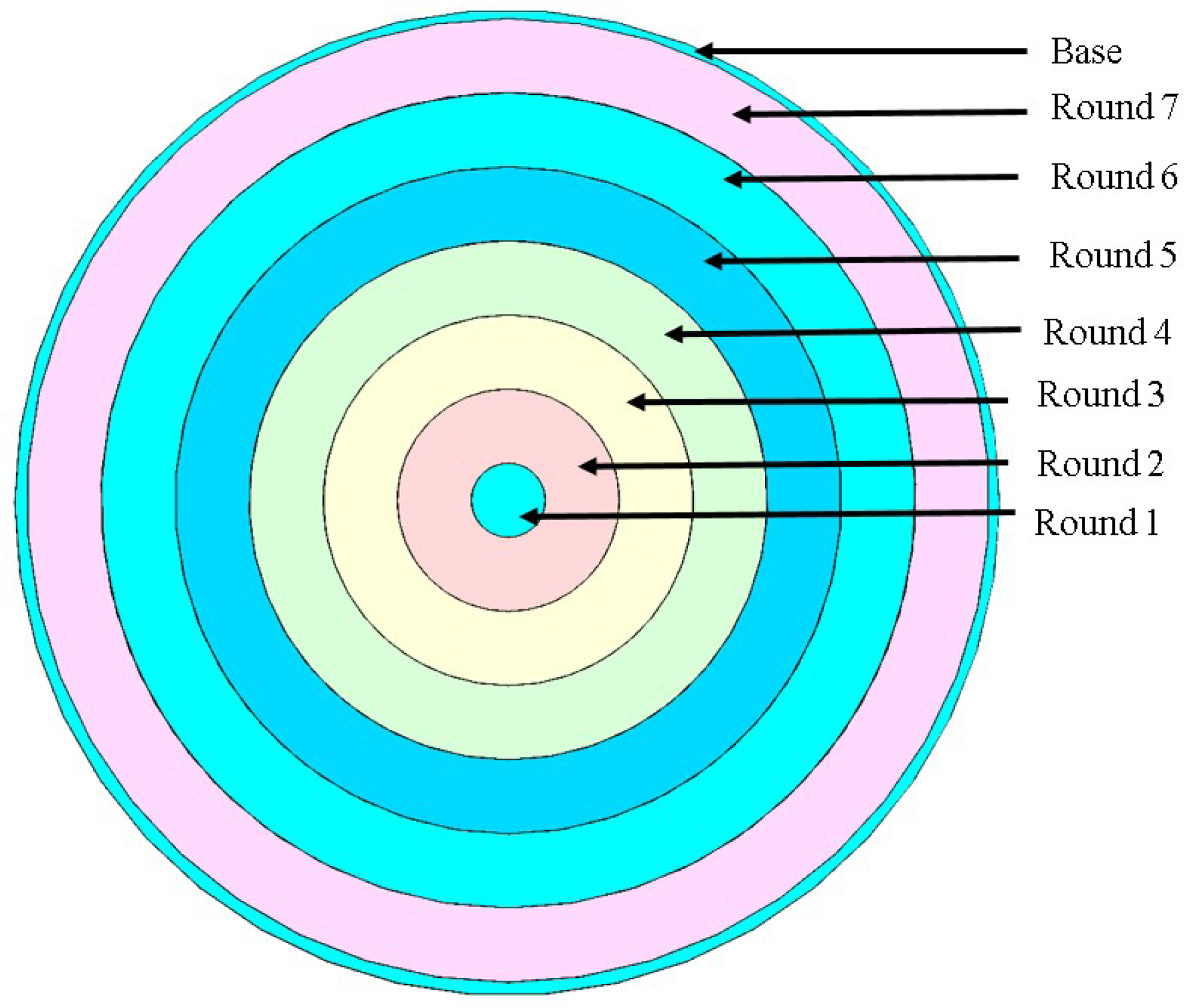
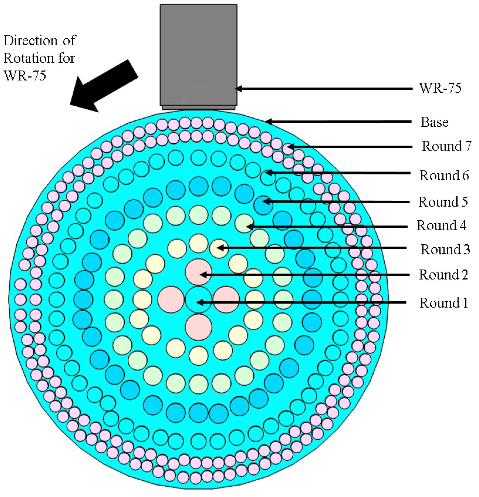
3.2. Placement of Cylindrical Units Based on Radial Distance
As described previously in Section 3.1, the respective cylindrical rods are placed for defined circular rings. In total, there are seven different rounds which are indicated by seven different colors as Round 1, Round 2, Round 4, Round 5, Round 6 and Round 7, where the cylindrical rods have the permittivity values varying as of 1.99, 1.95, 1.86, 1.72, 1.54, 1.32 and 1.05, respectively. This extends from the center towards the edge where the diameter of cylindrical rods is greater within the center region where as its radius gets decreased toward the edge. For seven different rounds of Round 1, Round 2, Round 4, Round 5, Round 6 and Round 7 the respective cylindrical rods radii are 3.5 mm, 3.5 mm, 2.5 mm, 2.5 mm, 2.5 mm, 2 mm and 1.5 mm. Similarly, the number of cylindrical rods in Round 1, Round 2, Round 4, Round 5, Round 6 and Round 7 are respectively 1, 4, 16, 24, 32, 51 and 175. The cylindrical rods have a uniform height of 11 mm where the base is 1.5 mm in thickness. The diameter of the base is 100 mm, which is the same as of the two parallel plate’s diameters. The regions of the respective circular rings depend on the Luneburg lens principle. The number of cylindrical rods is adjusted in the analytical form so that adjacent cylinders does not overlap to each other. The cylinder height is kept constant to maintain a fixed gap between two parallel plates, which determines the thickness of the considered plates that operate in TE10 mode. Figure 4 shows the respective cylindrical rods arrangement with a feed of the WR-75 waveguide along with its direction of rotation. The rotation of WR-75 is in the counter clockwise direction for , , , and angles.
Figure 4.
Arrangement of cylindrical rods in defined seven circular rings.
4. Results and Discussion
Waveguide WR-75 is used as a feed source with iris effect that shows matching behavior within the frequency band of operation from 10 GHz to 15 GHz. The extra metal plate is designed with the internal dimension of 15 mm × 7.5 mm that is kept at the mouth of the waveguide. The angular rotation of , , , and are maintained with anticlockwise rotation that shows the beam steering characteristics as described in further sections. We have considered the simulation mesh as cells per wavelength values to maintain the simulation resolution. The Model and Background are set to four and cells per maximum model box edge have a Model of 10 and Background of 1, which shows that the numerical convergence has been reached for the obtained simulation results. Similarly, the waveguide port boundary condition is considered to obtain the simulated values.
4.1. Radiation Patterns Obtained with Rings
The simulated steering pattern as resulted with the defined seven circular rings for 10 GHz, 11 GHz, 12 GHz, 13 GHz, 14 GHz and 15 GHz are shown in Figure 5a–f for various angles of rotation of the WR-75 waveguide. This figure shows the drop in value of the peak main beam from 11.9 dB, 11.2 dB, 10.8 dB, 10.6 dB and 10.1 dB for , , , and angles of rotation of the waveguide, respectively, in the 12 GHz design frequency. This might be due to the increase in side lobe label of −11.2 dB, −8.4 dB, −8.1 dB, −9.2 dB and −8.3 dB for WR-75 waveguide angle of rotation of , , , and , respectively. As observed, the main beam deviated to the average elevation angle () value of , , , and for counter clockwise rotation angles () for WR-75 of , , , and , respectively.
Figure 5.
(a–f) Simulated steered radiated beam for circular rings pattern in 10 GHz, 11 GHz, 12 GHz, 13 GHz, 14 GHz and 15 GHz frequencies.
4.2. Radiation Patterns Obtained with Placement of Cylindrical Rods
The simulated radiation patterns thus obtained after keeping cylindrical rods for 10 GHz, 11 GHz, 12 GHz, 13 GHz, 14 GHz and 15 GHz are shown in Figure 6a–f in various angles of rotations as of , , , and for WR-75 waveguide. As observed, a relative decrease in the peak value is noted this might be due to the arrangement of cylindrical rods. Additionally, the main beam is deviated to the average elevation angle () of , , , and for a counter clockwise rotation angle () for WR-75 of , , , and , respectively.
Figure 6.
(a–f) Simulated steered radiated beam obtained after the placement of cylindrical rods in 10 GHz, 11 GHz, 12 GHz, 13 GHz, 14 GHz and 15 GHz frequencies.
In order to verify the concept, we have fabricated the proposed prototype through a Stratasys J750 3D printer using VERO CMYK material, whose permittivity () is 2.8 and loss tangent (tan) is 0.124, as described in []. The beam deviation has been observed for five different rotation angles of the waveguide. To verity our proof of concept, we have considered two rotation angles namely , , in the measurement scenario whose radiation plots are shown in Figure 7. The radiation plots are well matched for the required 10 to 15 GHz frequencies range except at the corner frequencies. Especially at 10 and 15 GHz frequencies, there is a slight deviation in the peak values, as noticed in Figure 7a,f respectively, which might be due to the frequency limitation and alignment of WR-75 waveguide to the gap of parallel plates. However, these slight variations have no effect on the measured results for other frequencies of interest. During the experimental setup, the fixed gap is maintained between the two parallel plates through a 3D printed prototype. The WR-75 waveguide is maintained across the edge of parallel plates for fixed values of rotation angles through paper tapes. These experimental results are modeled and numerically solved through a Nearfield Systems Incorporated 2000 antenna measurement system by noting the Amplitude, in dB, versus Azimuth, in degrees. The measurement of the proposed prototype inserted between two parallel plates is performed in NSI-700S-50 spherical near-field measurement system at the Australian Antenna Measurement Facility. The experimental setup is shown in Figure 8.
Figure 7.
(a–f) Simulated and measured steered radiated beam obtained after rotation of feed waveguide in 10 GHz, 11 GHz, 12 GHz, 13 GHz, 14 GHz and 15 GHz frequencies.
Figure 8.
Measurement system setup in anechoic chamber. Attached index figures shows fabricated prototype and assembled system with parallel plates and waveguide.
4.3. Characteristic Plots and Comparison Table
The simulated pattern of peak directivity and gain plots as well as the side lobe level variation after the placement of cylindrical rods in defined circular ring regions are shown in Figure 9a,b, respectively. As noticed, in the design operation frequency of 12 GHz, simulated peak directivity and gain values are 11.9, 11.2, 10.8, 10.6, 10.1 dBi and 11.7, 10.9, 10.4, 10.3, 9.87 dBi, respectively for , , , and of WR-75 waveguide counter clockwise direction, which shows the decreasing trend in its values. Similarly, side lobe levels are −11.2 dB, −8.4 dB, −8.1.6 dB, −9.2 dB and −8.3 dB for the rotation of the WR-75 waveguide in , , , and in the counter clockwise direction.
Figure 9.
(a) Distribution of simulated peak directivity and gain values. (b) Side lobe levels plot in 10 GHz, 11 GHz, 12 GHz, 13 GHz, 14 GHz and 15 GHz frequencies.
In addition, we have plotted the measured directivity and gain plots against the simulated values for , angles of rotation of WR-75 waveguide, which is shown in Figure 10a. This figure highlights the matching trends for simulated and measured directivity and gain patterns. The measured values of directivity and gain in condition at 11, 12 and 14 GHz are 11.5, 11.01 dBi; 12.5, 12.08 dBi; and 12.6, 12.33 dBi, respectively. Similarly measured directivity and gain values in condition at 11, 12 and 14 GHz are 10.84, 10.56 dBi; 11.16, 10.98 dBi; and 12.23, 11.59 dBi, respectively. Interestingly, these are comparable to the simulated values and are less than 3dB in difference between directivity and gain margin. This signifies the lower loss behavior of the material under consideration. Similarly, Figure 10b shows the simulated and measured return loss plot for rotation angles of , , , and for WR-75 waveguide. This plot signifies the matching of proposed antenna structure throughout the operating frequency band where its values are less than 2.2, expect for the measured case which might be due to the arrangement of cylinders within the defined circular regions of the proposed prototype.
Figure 10.
(a) Distribution of simulated and measured peak directivity and gain values for , angles of rotation of WR-75 waveguide. (b) Simulated and measured voltage standing wave ratio (VSWR) plots for , , , and angles of rotation of the WR-75 waveguide.
Moreover, we have analyzed the cross polarization values for both , angles of rotation of WR-75 waveguide, which are shown in Figure 11a,b. In the angles of rotation case, the observed cross polarization values are below −7 dBi where as in the case, its values are below -12 dBi. However, most of the values lie in between −15 dBi to −35 dBi, which signifies the better matching behavior in operating frequency ranging from 10 GHz to 15 GHz with respect to lower cross polarization with the minimum loss of signals at the receiver end.
Figure 11.
Noted cross polarized values, (a) (b) angles of rotation of WR-75 waveguide.
Similarly, the comparison of proposed antenna prototype with other structures is shown in Table 1. This shows the proposed antenna prototype gives wideband beam deviation that is observed across the frequency range from 10 GHz to 15 GHz. Additionally, the side lobe levels are lower than −6 dB for operating Ku-band frequency range, and the proposed prototype is 100 mm in diameter, which is comparatively smaller as compared with other proposed antenna structures. The design goal of proposed structure is to show beam deviating characteristics from 10 GHz to 15 GHz maintaining higher values of directivity and gain margins, as obtained from the 3D printed prototype that is light in weight of 179 g. This signifies the importance of the proposed 3D printed structure fabricated from Multijet 3D printing process.
Table 1.
Comparison of proposed antenna structure.
5. Conclusions
In this study, we have presented the use of additive manufacturing techniques for steering the beam direction. The use of parallel plates eventually decreased the profile of the Luneburg lens and the respective arrangement of cylindrical rods shows the steering characteristics, as shown from 10 GHz to 15 GHz. The measured directivity and gain values are relatively higher which are of around 14.7 and 12.7 dBi. The parallel plate structure has been excited in the dominant mode of TE with reasonably good results in radiation patterns with lower side lobe levels and less cross polarization values that are of below −6 dB and −15 dBi, respectively. The weight of the overall proposed system is about 179 g, which shows the systems are light in weight. Similarly, the simulated and measured VSWR plots are less than 2.2 over the frequency of interest. This signifies the matching over the operating frequency range that cover the Ku-band region.
Author Contributions
Conceptualization, S.S.; Data curation, S.S.; Formal analysis, S.S.; Investiga-tion, S.S.; Methodology, S.S.; Project administration, S.S.; Resources, S.S.; Software, S.S.; Validation, S.S.; Visualization, S.S.; Writing-original draft, S.S.; Funding acquisition, S.M.A., M.A. and K.P.E.; Supervision, S.M.A., M.A. and K.P.E.; writing—review and editing, S.S., S.M.A., M.A. and K.P.E. All authors have read and agreed to the published version of the manuscript.
Funding
This work was supported in part by the Australian Research Council (ARC), and in part by the Macquarie University International Research Excellence Scholarship (iMQRES), 45035091.
Institutional Review Board Statement
Not applicable.
Informed Consent Statement
Not applicable.
Data Availability Statement
Not applicable.
Acknowledgments
We want to extend thankfulness to CSIRO, Marsfield, NSW, Australia and Macquarie University for providing support for measurement of antenna prototype.
Conflicts of Interest
The authors declare no conflict of interest.
References
- Artemenko, A.; Maltsev, A.; Mozharovskiy, A.; Sevastyanov, A.; Ssorin, V.; Maslennikov, R. Millimeter-wave electronically steerable integrated lens antennas for WLAN/WPAN applications. IEEE Trans. Antennas Propag. 2012, 61, 1665–1671. [Google Scholar] [CrossRef]
- Yi, J.; Burokur, S.N.; de Lustrac, A. Experimental validation of a transformation optics based lens for beam steering. Appl. Phys. Lett. 2015, 107, 154101. [Google Scholar] [CrossRef]
- Jianjia, Y.; Burokur, S.N.; Piau, G.P.; de Lustrac, A. Coherent beam control with an all-dielectric transformation optics based lens. Sci. Rep. 2016, 6, 18819. [Google Scholar]
- Abbasi, M.I.; Dahri, M.H.; Jamaluddin, M.H.; Seman, N.; Kamarudin, M.R.; Sulaiman, N.H. Millimeter wave beam steering reflectarray antenna based on mechanical rotation of array. IEEE Access 2019, 7, 145685–145691. [Google Scholar] [CrossRef]
- Massaccesi, A.; Dassano, G.; Pirinoli, P. Beam scanning capabilities of a 3d-printed perforated dielectric transmitarray. Electronics 2019, 8, 379. [Google Scholar] [CrossRef] [Green Version]
- Shrestha, S.; Choi, D.Y. Rain Attenuation Study at Ku-Band over Earth-Space Path in South Korea. Adv. Astron. 2019, 2019, 9538061. [Google Scholar] [CrossRef]
- Shrestha, S.; Choi, D.Y. Characterization of rain specific attenuation and frequency scaling method for satellite communication in South Korea. Int. J. Antennas Propag. 2017, 2017, 8694748. [Google Scholar] [CrossRef]
- Jia, D.; He, Y.; Ding, N.; Zhou, J.; Du, B.; Zhang, W. Beam-steering flat lens antenna based on multilayer gradient index metamaterials. IEEE Antennas Wirel. Propag. Lett. 2018, 17, 1510–1514. [Google Scholar] [CrossRef]
- Li, Y.; Ge, L.; Chen, M.; Zhang, Z.; Li, Z.; Wang, J. Multibeam 3-D-printed Luneburg lens fed by magnetoelectric dipole antennas for millimeter-wave MIMO applications. IEEE Trans. Antennas Propag. 2019, 67, 2923–2933. [Google Scholar] [CrossRef]
- Dhouibi, A.; Burokur, S.N.; de Lustrac, A. Planar metamaterial-based beam-scanning broadband microwave antenna. J. Appl. Phys. 2014, 115, 194901. [Google Scholar] [CrossRef] [Green Version]
- Bosiljevac, M.; Casaletti, M.; Caminita, F.; Sipus, Z.; Maci, S. Non-uniform metasurface Luneburg lens antenna design. IEEE Trans. Antennas Propag. 2012, 60, 4065–4073. [Google Scholar] [CrossRef]
- Pfeiffer, C.; Grbic, A. A printed, broadband Luneburg lens antenna. IEEE Trans. Antennas Propag. 2010, 58, 3055–3059. [Google Scholar] [CrossRef]
- Lu, H.; Liu, Z.; Liu, Y.; Ni, H.; Lv, X. Compact air-filled Luneburg lens antennas based on almost-parallel plate waveguide loaded with equal-sized metallic posts. IEEE Trans. Antennas Propag. 2019, 67, 6829–6838. [Google Scholar] [CrossRef]
- Hua, C.; Wu, X.; Yang, N.; Wu, W. Air-filled parallel-plate cylindrical modified Luneberg lens antenna for multiple-beam scanning at millimeter-wave frequencies. IEEE Trans. Microw. Theory Tech. 2012, 61, 436–443. [Google Scholar] [CrossRef]
- Wu, X.; Laurin, J.J. Fan-beam millimeter-wave antenna design based on the cylindrical Luneberg lens. IEEE Trans. Antennas Propag. 2007, 55, 2147–2156. [Google Scholar] [CrossRef]
- Chou, H.T.; Yan, Z.D. Parallel-plate Luneburg lens antenna for broadband multibeam radiation at millimeter-wave frequencies with design optimization. IEEE Trans. Antennas Propag. 2018, 66, 5794–5804. [Google Scholar] [CrossRef]
- Manoochehri, O.; Darvazehban, A.; Salari, M.A.; Emadeddin, A.; Erricolo, D. A parallel plate ultrawideband multibeam microwave lens antenna. IEEE Trans. Antennas Propag. 2018, 66, 4878–4883. [Google Scholar] [CrossRef]
- Molina, H.B.; Marin, J.G.; Hesselbarth, J. Modified planar Luneburg lens millimetre-wave antenna for wide-angle beam scan having feed locations on a straight line. IET Microwaves, Antennas Propag. 2017, 11, 1462–1468. [Google Scholar] [CrossRef]
- Liu, P.; Zhu, X.W.; Zhang, Y.; Li, J.; Jiang, Z. 3D-printed cylindrical Luneburg lens antenna for millimeter-wave applications. Int. J. RF Microw. Comput. Aided Eng. 2020, 30, e21994. [Google Scholar] [CrossRef]
- Liu, K.; Yang, S.; Jiang, Q.; Qu, S.W. A lightweight multi-beam cylindrical Luneberg lens antenna loaded with multiple dielectric posts. Int. J. RF Microw. Comput. Aided Eng. 2019, 29, e21511. [Google Scholar] [CrossRef]
- Shrestha, S.; Zahra, H.; Abbasi, M.A.B.; Asadnia, M.; Abbas, S.M. Increasing the directivity of resonant cavity antennas with nearfield transformation meta-structure realized with stereolithograpy. Electronics 2021, 10, 333. [Google Scholar] [CrossRef]
- Shrestha, S.; Baba, A.A.; Abbas, S.M.; Asadnia, M.; Hashmi, R.M. A horn antenna covered with a 3D-printed metasurface for gain enhancement. Electronics 2021, 10, 119. [Google Scholar] [CrossRef]
- Shrestha, S.; Zahra, H.; Abbas, S.M.; Kiyani, A.; Mohamadzade, B.; Asadnia, M. Generation of Beam Tilt through Three-Dimensional Printed Surface. Electronics 2021, 10, 3174. [Google Scholar] [CrossRef]
- Shrestha, S.; Zahra, H.; Kiyani, A.; Asadnia, M.; Abbas, S.M.; Mahmoud, A. Miniaturized Wideband Antenna Prototype Operating over the Ku-Band. Micromachines 2022, 13, 471. [Google Scholar] [CrossRef] [PubMed]
- Zou, Z.Y.; Lou, Y.H.; Song, X.Q.; Jiang, H.; Du, K.; Yin, C.Z.; Lu, W.Z.; Wang, X.C.; Wang, X.H.; Fu, M.; et al. Near-Zero Thermal Expansion Ba1- xSrxZn2Si2O7-Based Microwave Dielectric Ceramics for 3D Printed Dielectric Resonator Antenna with Integrative Lens. Adv. Mater. Interfaces 2021, 8, 2100584. [Google Scholar] [CrossRef]
- Liu, B.; Sha, K.; Zhou, M.F.; Song, K.X.; Huang, Y.H.; Hu, C.C. Novel low-εr MGa2O4 (M= Ca, Sr) microwave dielectric ceramics for 5 G antenna applications at the Sub-6 GHz band. J. Eur. Ceram. Soc. 2021, 41, 5170–5175. [Google Scholar] [CrossRef]
- Sato, K.; Ujiie, H. A plate Luneberg lens with the permittivity distribution controlled by hole density. Electron. Commun. Jpn. Part I Commun. 2002, 85, 1–12. [Google Scholar] [CrossRef]
- Fan, F.; Cai, M.; Zhang, J.; Yan, Z.; Wu, J. Wideband low-profile Luneburg lens based on a glide-symmetric metasurface. IEEE Access 2020, 8, 85698–85705. [Google Scholar] [CrossRef]
Publisher’s Note: MDPI stays neutral with regard to jurisdictional claims in published maps and institutional affiliations. |
© 2022 by the authors. Licensee MDPI, Basel, Switzerland. This article is an open access article distributed under the terms and conditions of the Creative Commons Attribution (CC BY) license (https://creativecommons.org/licenses/by/4.0/).