
Formulas for Uniaxial Capacities of Tetrapod Bucket Foundations Considering Group Effects in Undrained Clay

 ,
,  and
and
Abstract
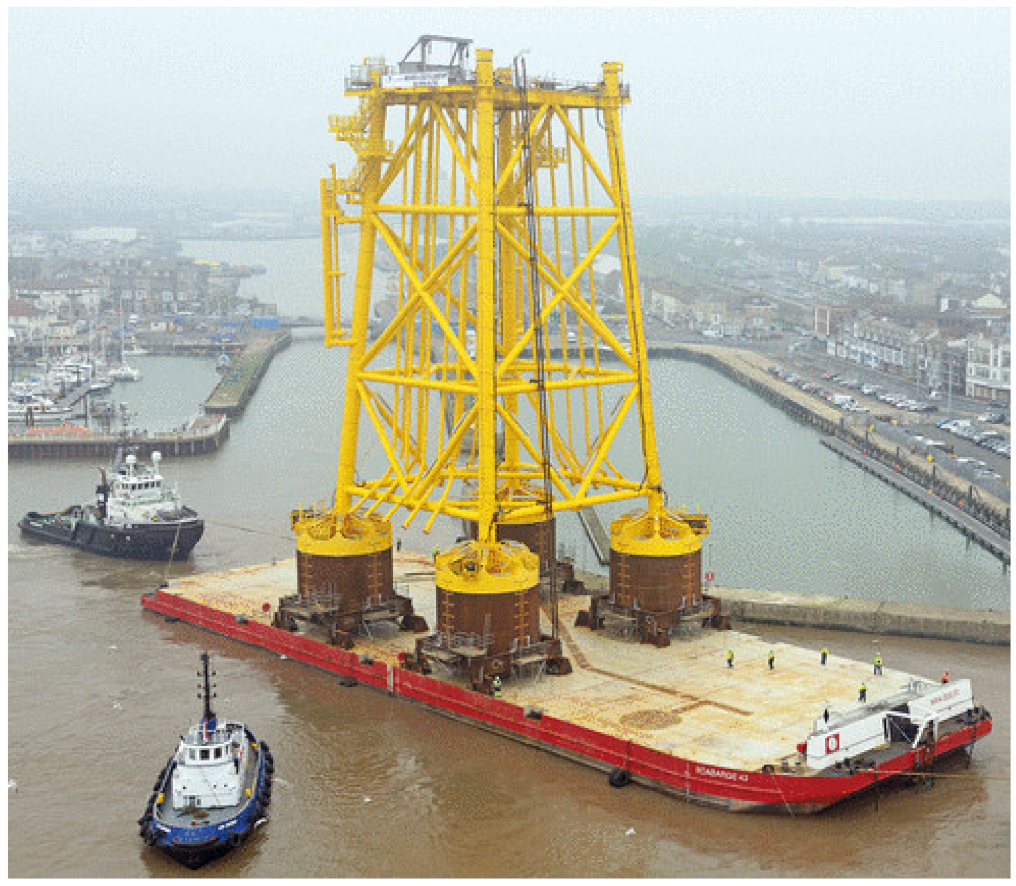
1. Introduction
2. Finite-Element Model
2.1. Property
2.2. Interaction
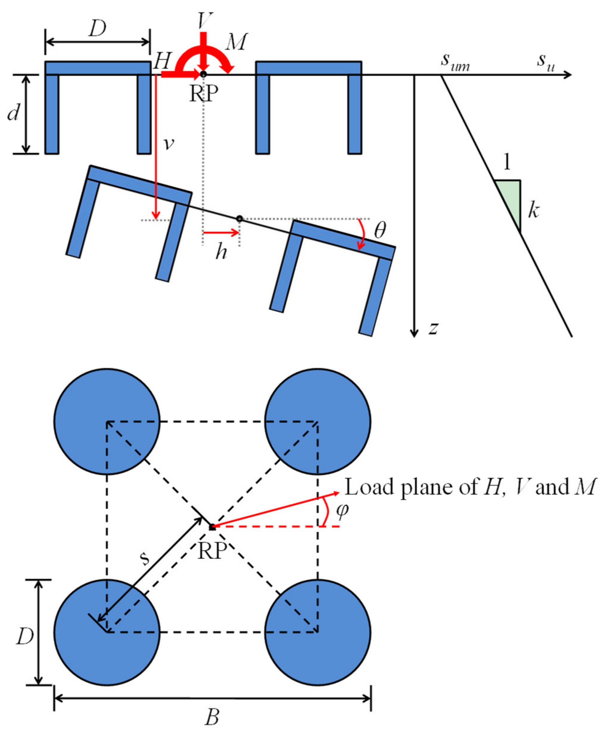
2.3. Load
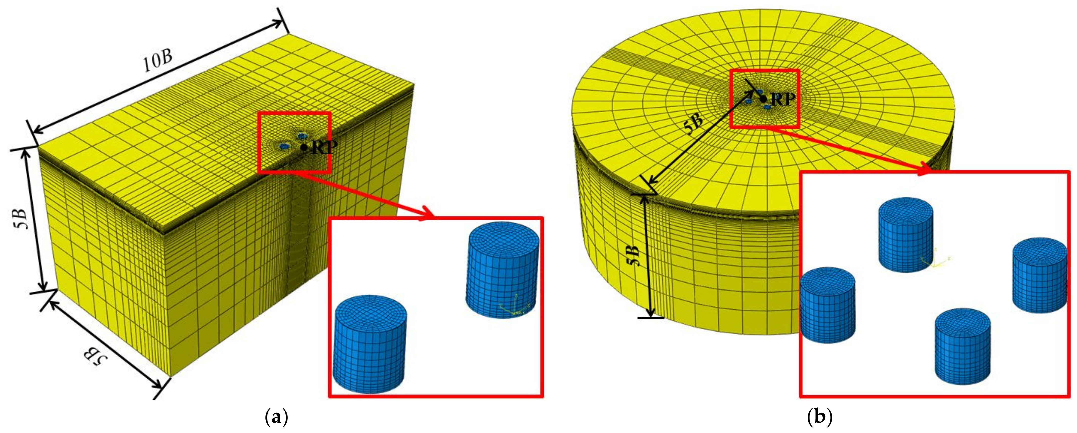
2.4. Mesh
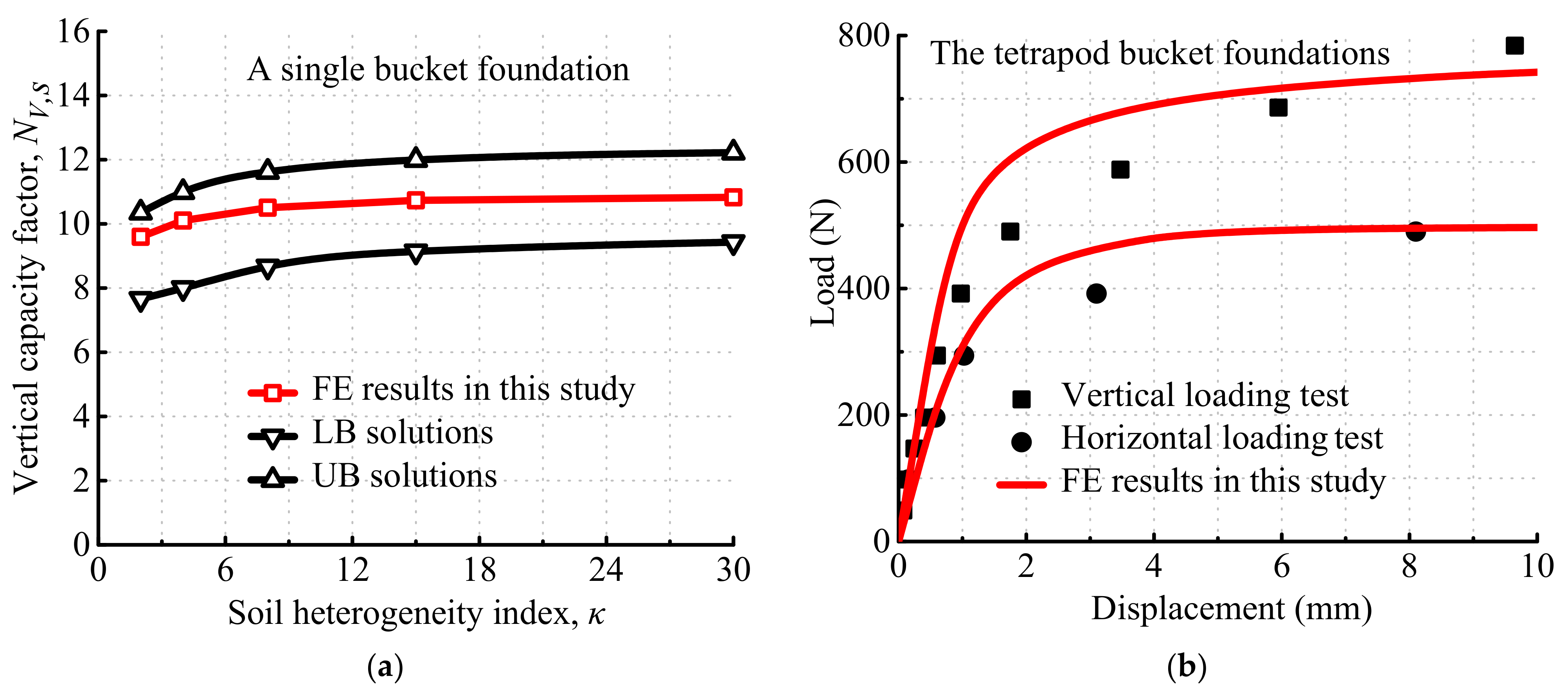
3. Validation
4. Capacities of the Single Bucket Foundation
5. Capacities of Tetrapod Bucket Foundations
5.1. Vertical Capacities
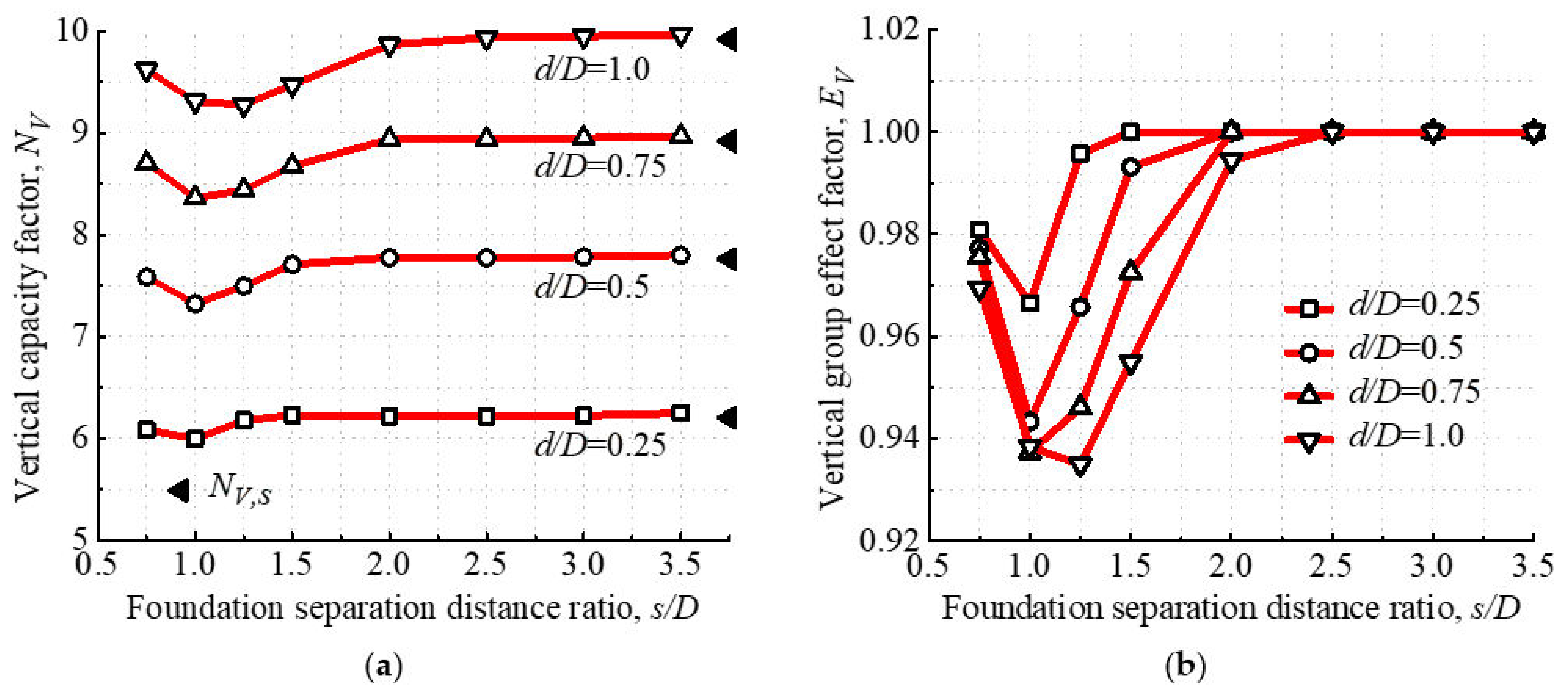
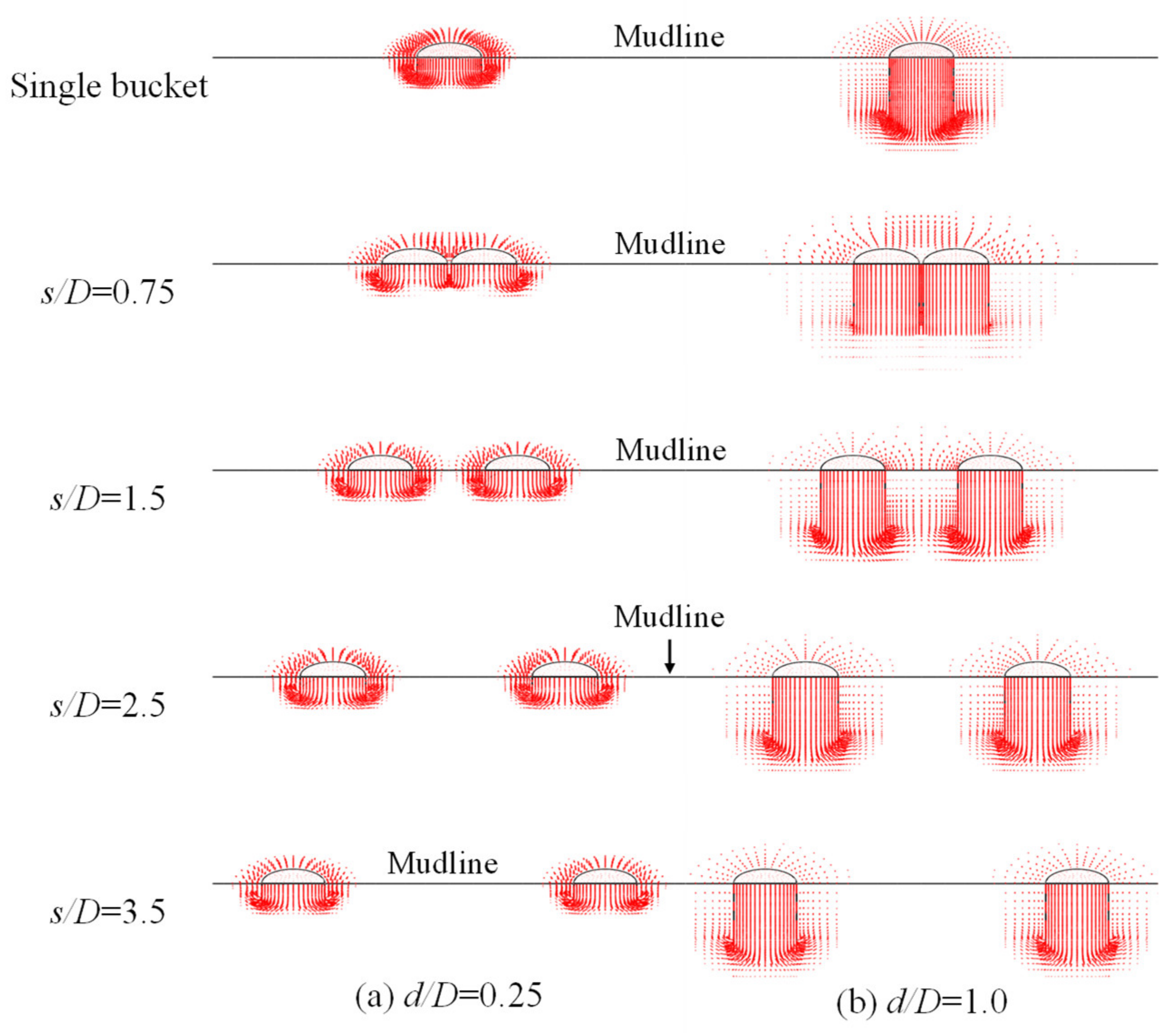
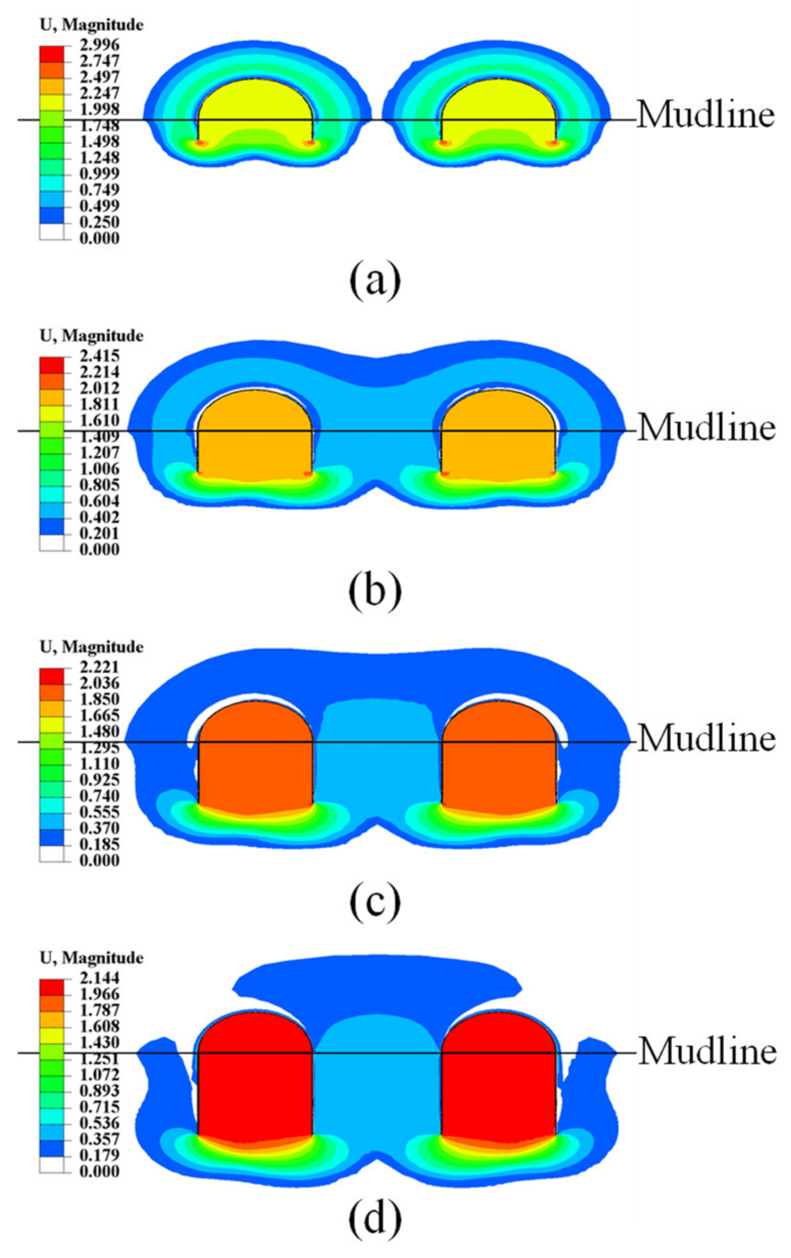
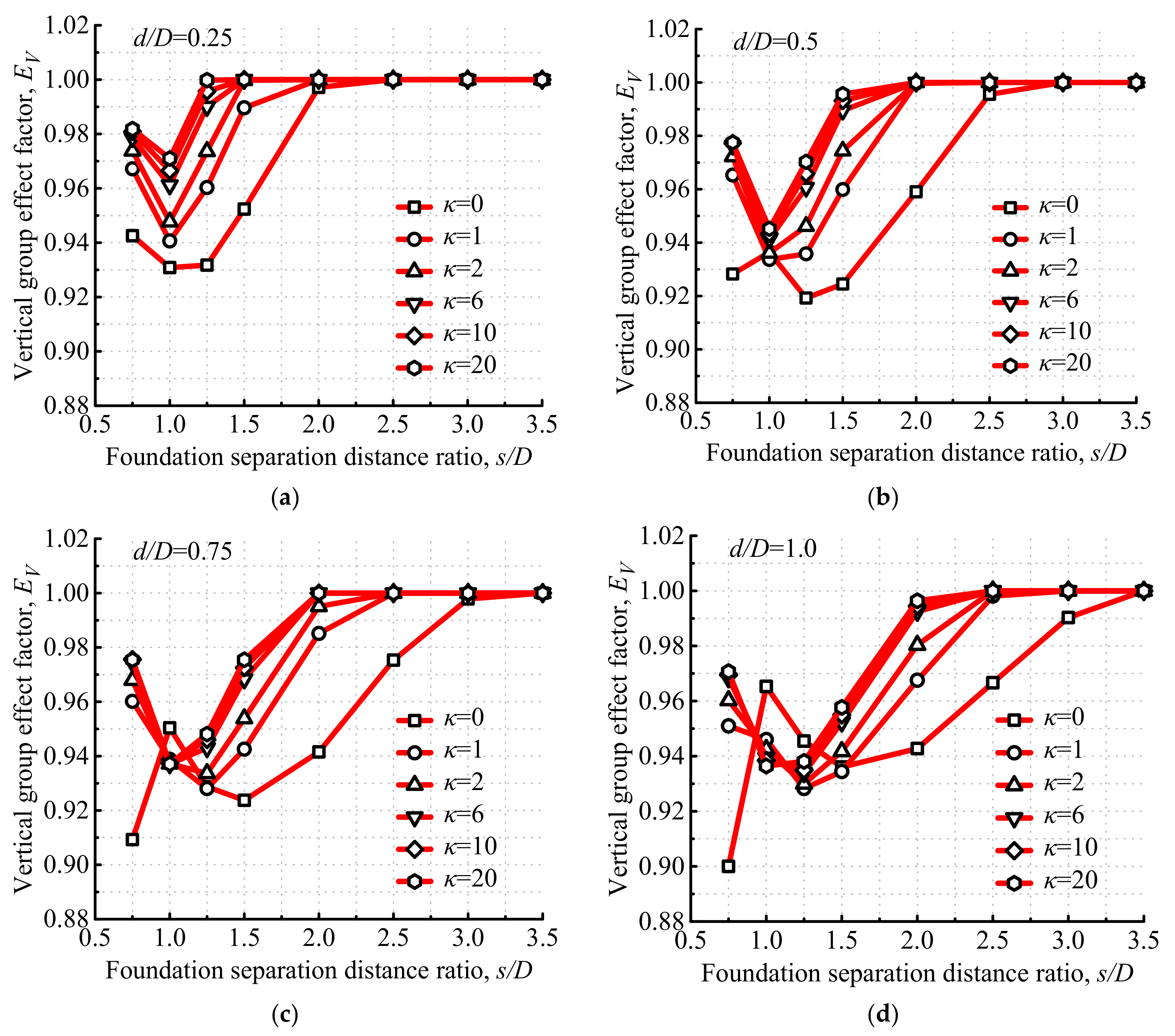
5.1.1. Effects of Foundation Separation Distance Ratio on Vertical Capacities
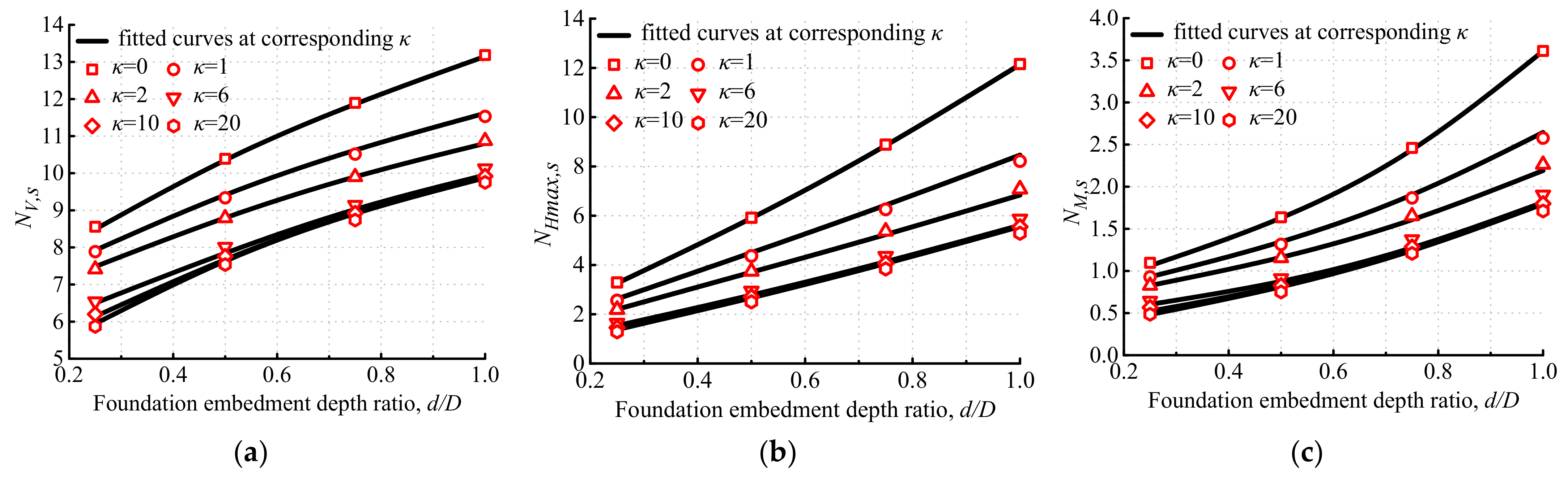
5.1.2. Effects of Foundation Embedment Depth Ratio on Vertical Capacities
5.1.3. Effects of the Soil-Strength Heterogeneity Index on Vertical Capacities
5.1.4. Formula for Vertical Capacities
5.2. Horizontal Capacities
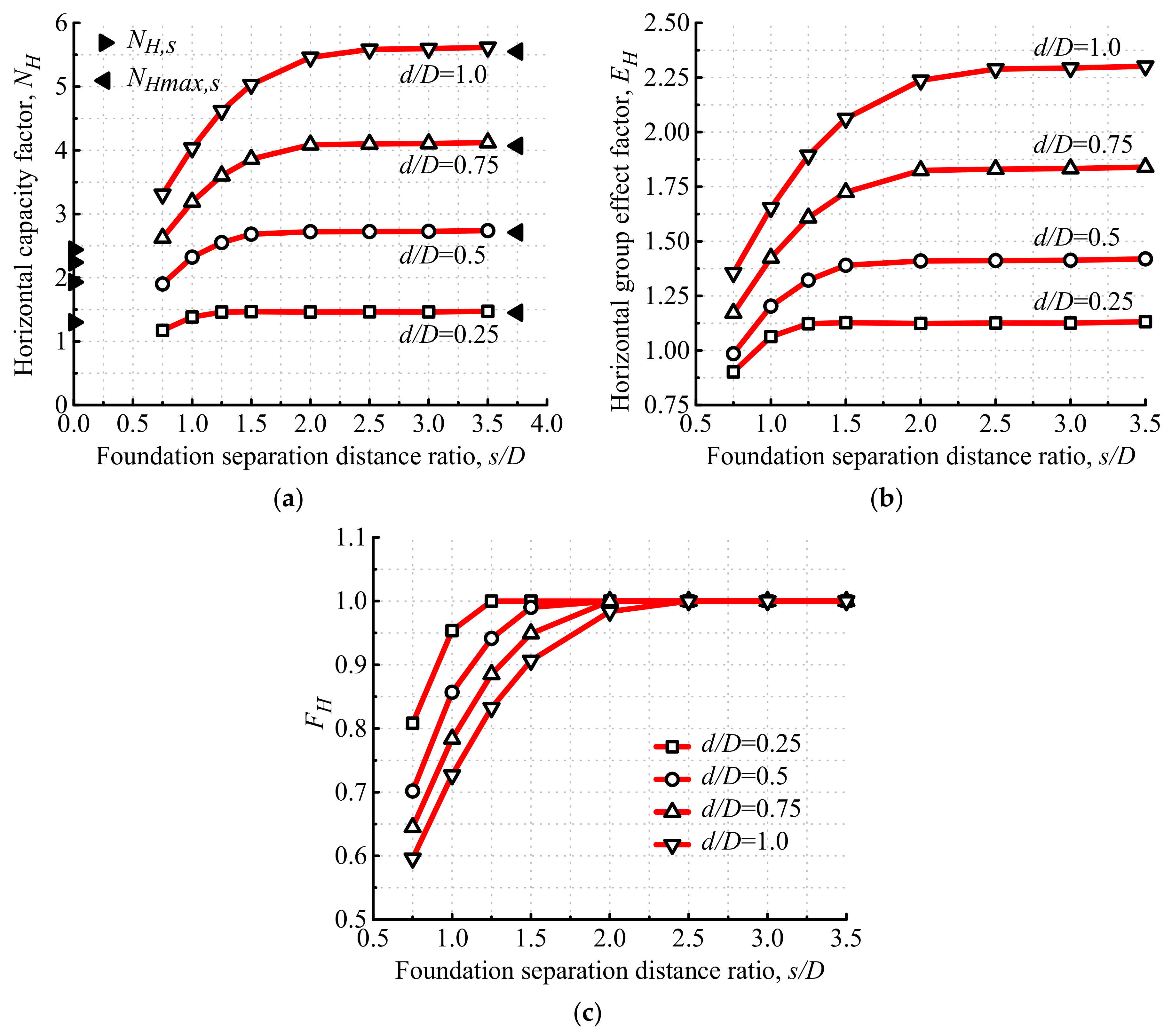
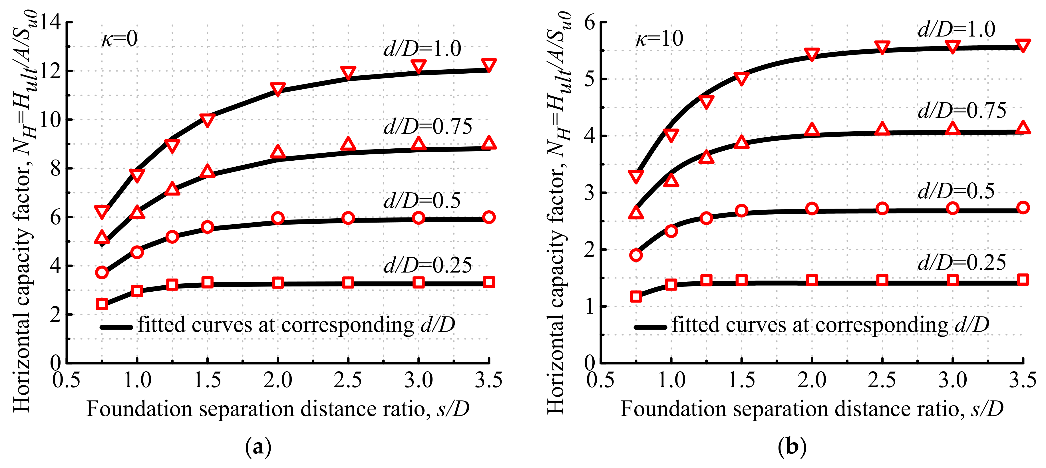
5.2.1. Effects of Foundation Separation Distance Ratio on Horizontal Capacities
5.2.2. Effects of the Foundation Embedment Depth Ratio on Horizontal Capacities
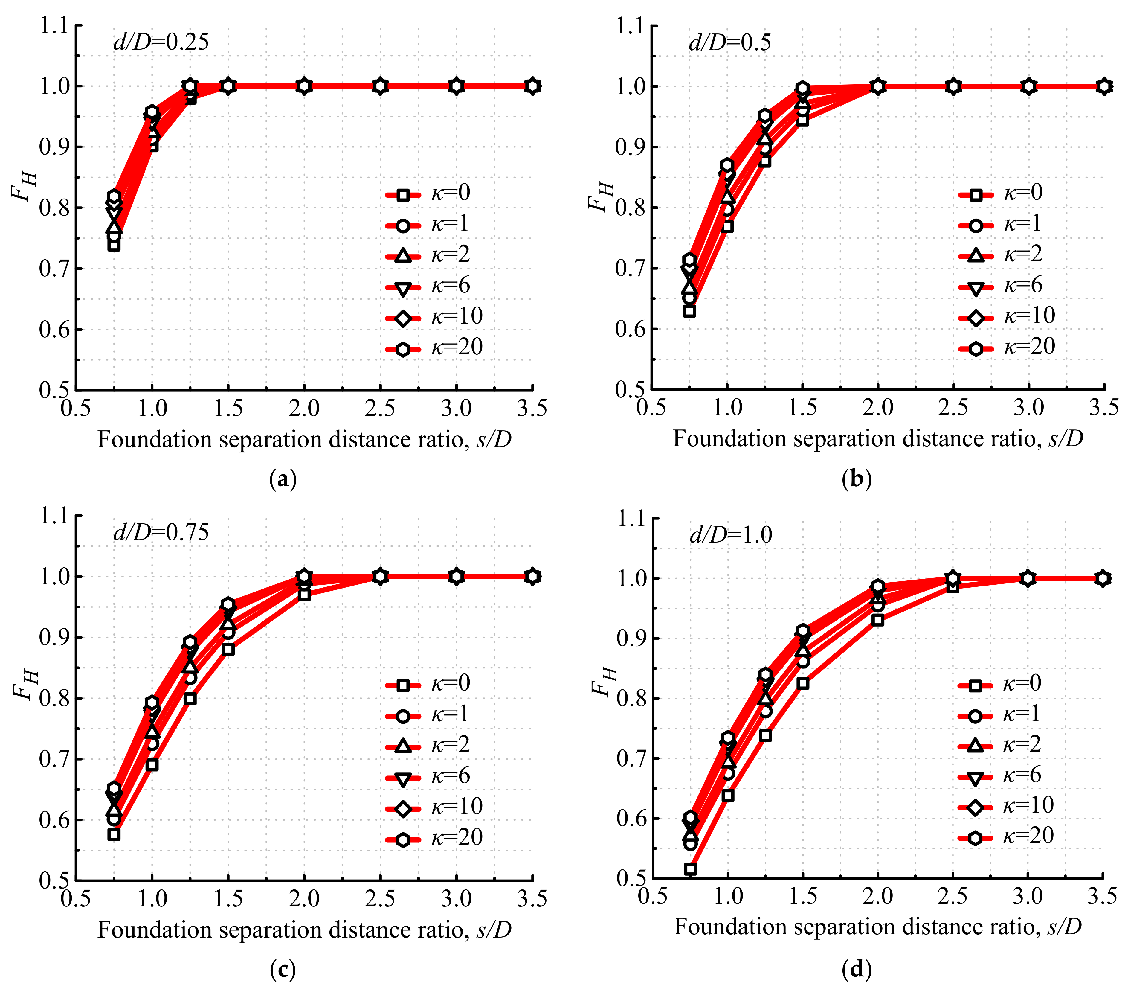
5.2.3. Effects of the Soil-Strength Heterogeneity Index on Horizontal Capacities
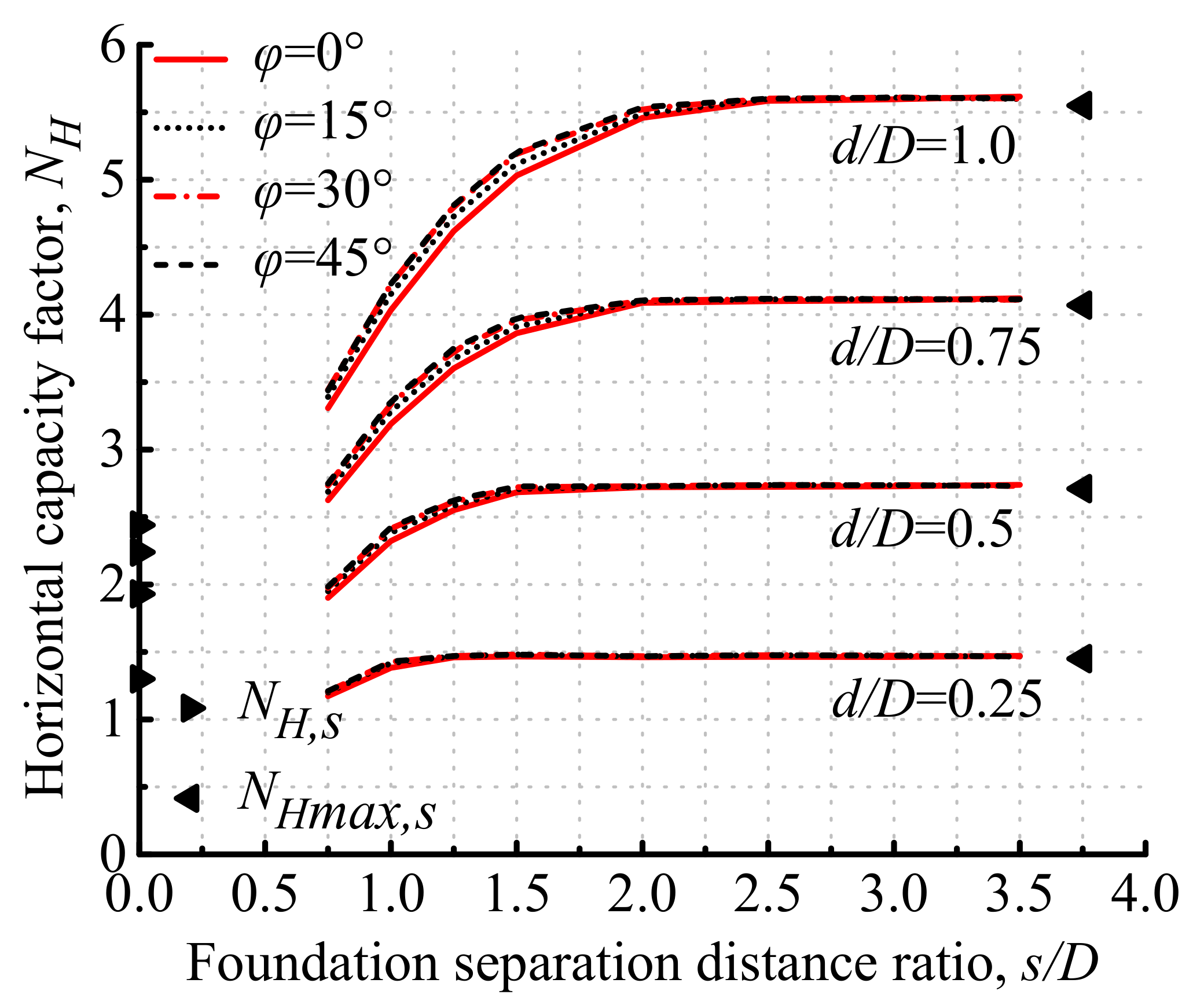
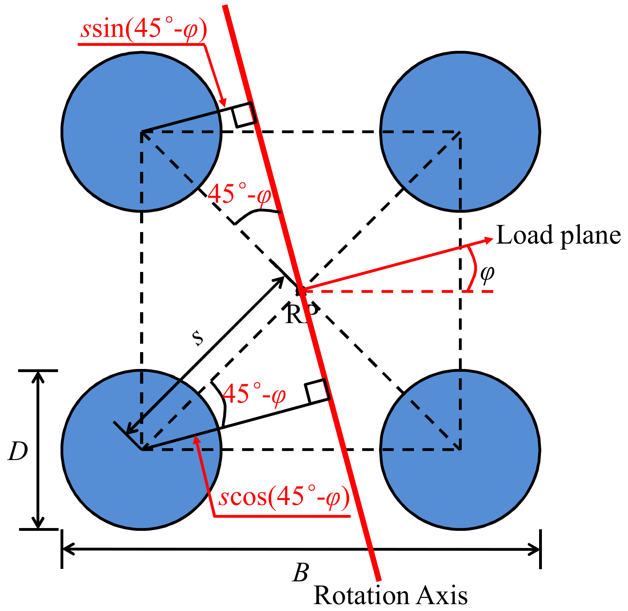
5.2.4. Effects of the Load Direction Angle on Horizontal Capacities
5.2.5. Formulas for Horizontal Capacities
5.3. Moment Capacities
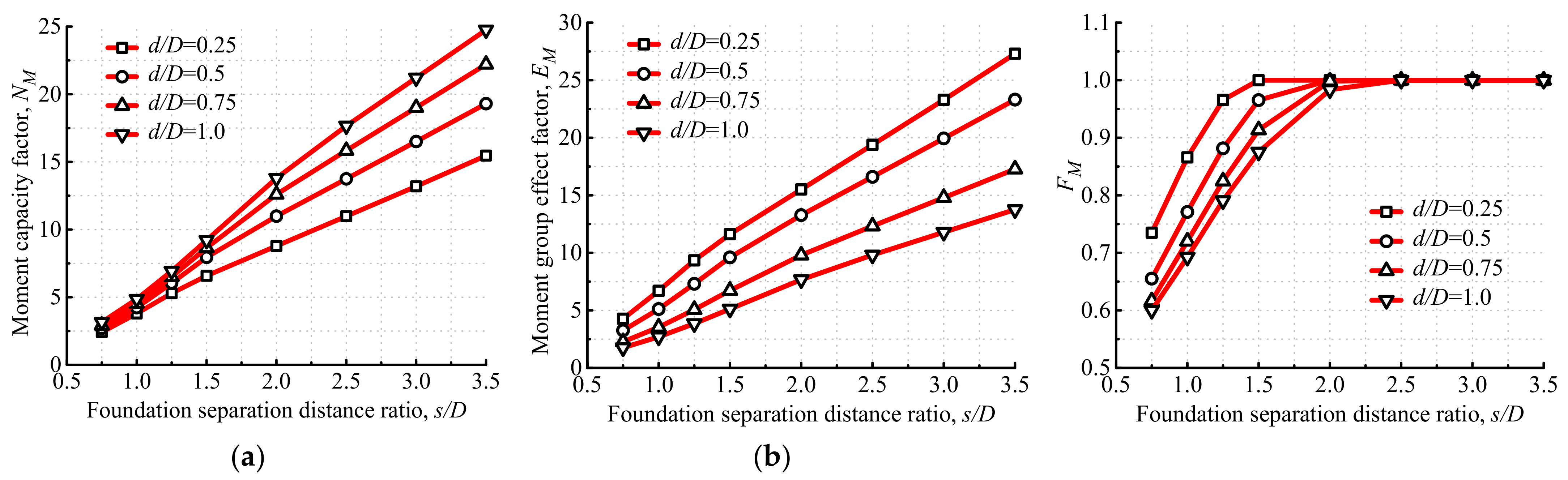
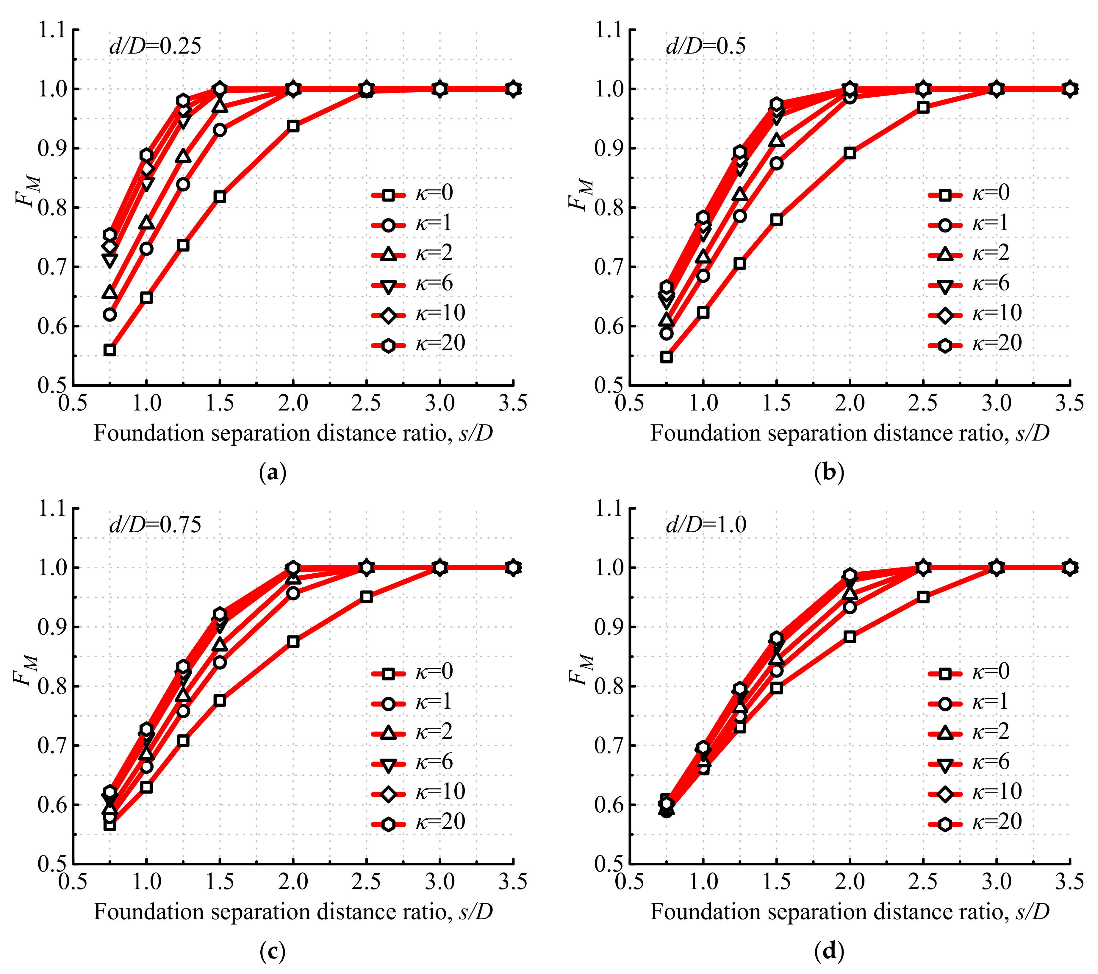
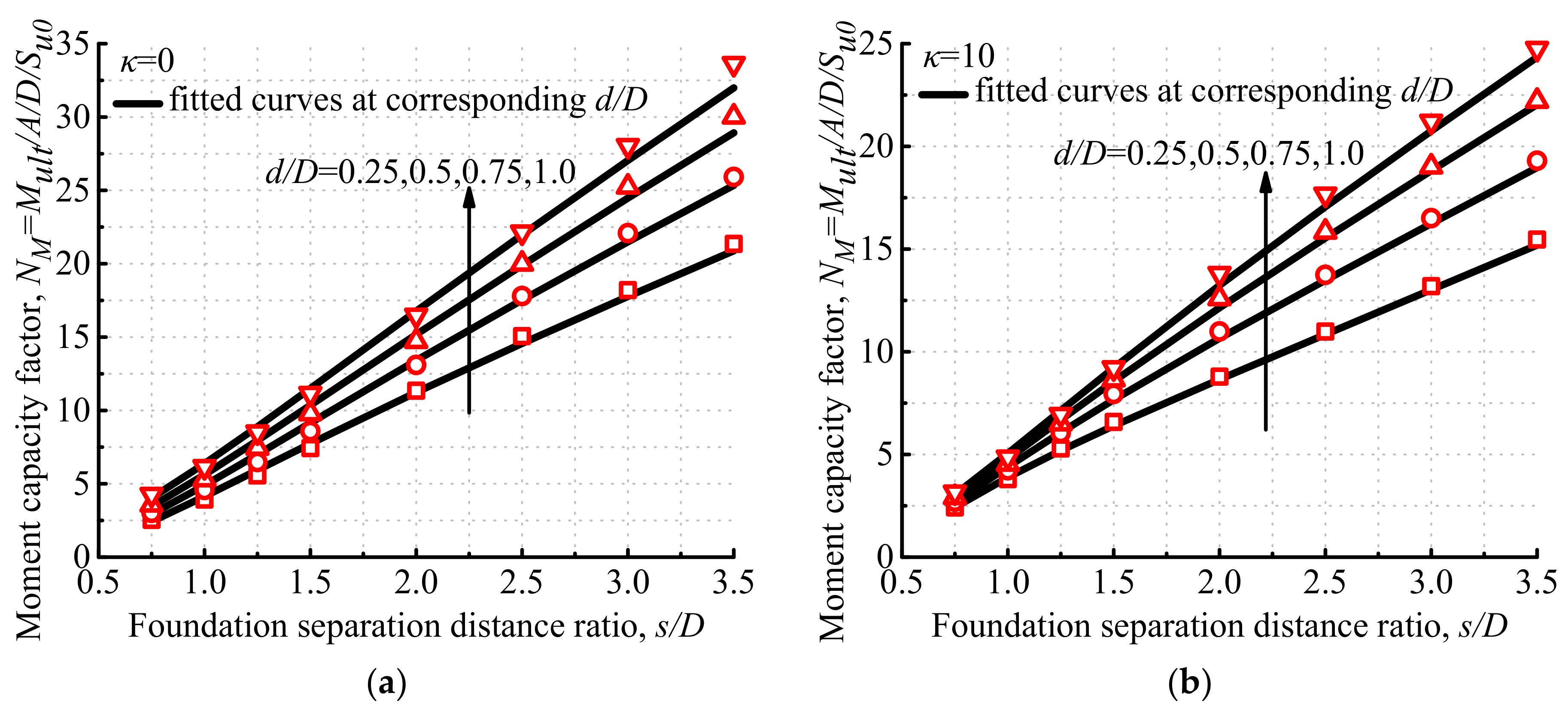
5.3.1. Effects of the Foundation Separation Distance Ratio on Moment Capacities
5.3.2. Effects of the Foundation Embedment Depth Ratio on Moment Capacities
5.3.3. Effects of the Soil-Strength Heterogeneity Index on Moment Capacities
5.3.4. Effects of the Load Direction Angle on Moment Capacities
5.3.5. Formulas for Moment Capacities
6. Conclusions
- (1)
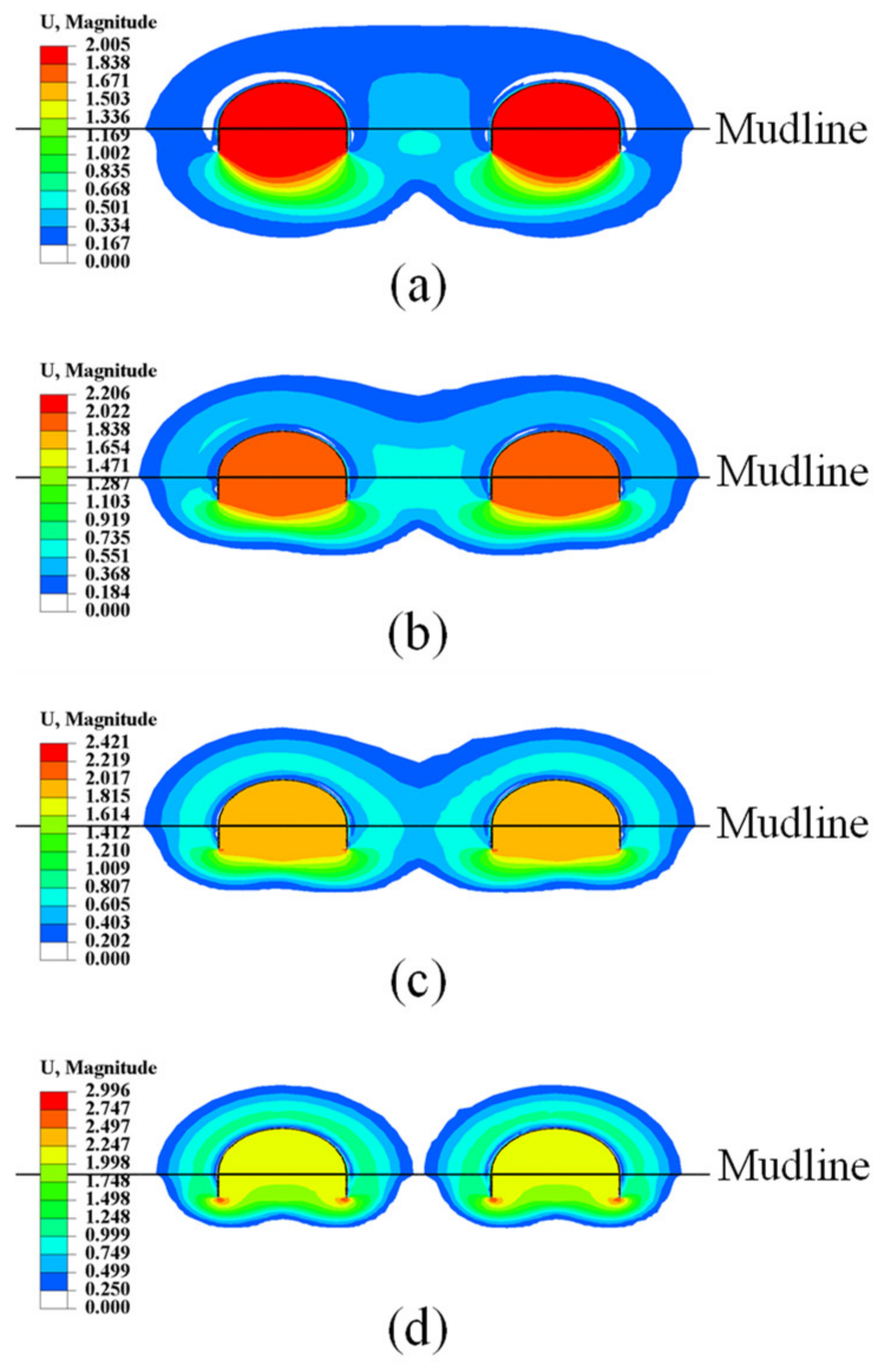
- The vertical capacity factor of the tetrapod bucket foundations (NV) increases as d/D increases, decreases as κ increases and changes quite insignificantly as s/D increases. NV almost equals NV,s, and the vertical group effect factor (EV) is among 0.9–1.0 for all cases in this study. Buckets and soils surrounded by them can be regarded as a whole when resisting vertical loading at a small s/D, while a Prandtl failure mechanism is observed for each bucket at a large enough s/D. The uniaxial vertical capacity of the tetrapod bucket foundations can be calculated through multiplying 4 times of that of a single bucket foundation by EV, which is taken as 0.9 based on conservative estimation.
- (2)
- As s/D increases, the horizontal capacity factor of tetrapod bucket foundations (NH) firstly enhances perceptibly and finally converges into the maximum horizontal capacity factor of the single bucket foundation (NHmax,s) corresponding to the motion mode of pure horizontal displacement. Meanwhile, NH increases with the increase in d/D and decreases with the increase in κ. NH with higher d/D or κ increases more visibly, compared to that of the single bucket foundation. The effect of the load direction angle (φ) on NH can be neglected. A tetrapod bucket foundation is more likely to move horizontally than to rotate, and its rotation angle (θ) gradually decreases with the increase in s/D and κ, as well as the decrease in d/D under the ultimate horizontal load. The uniaxial horizontal capacity of the tetrapod bucket foundations can be calculated through multiplying 4 times that of Hmax,s by the normalized horizontal group effect factor (FH), which is among 0.5–1.0 and is influenced by s/D, d/D and κ.
- (3)
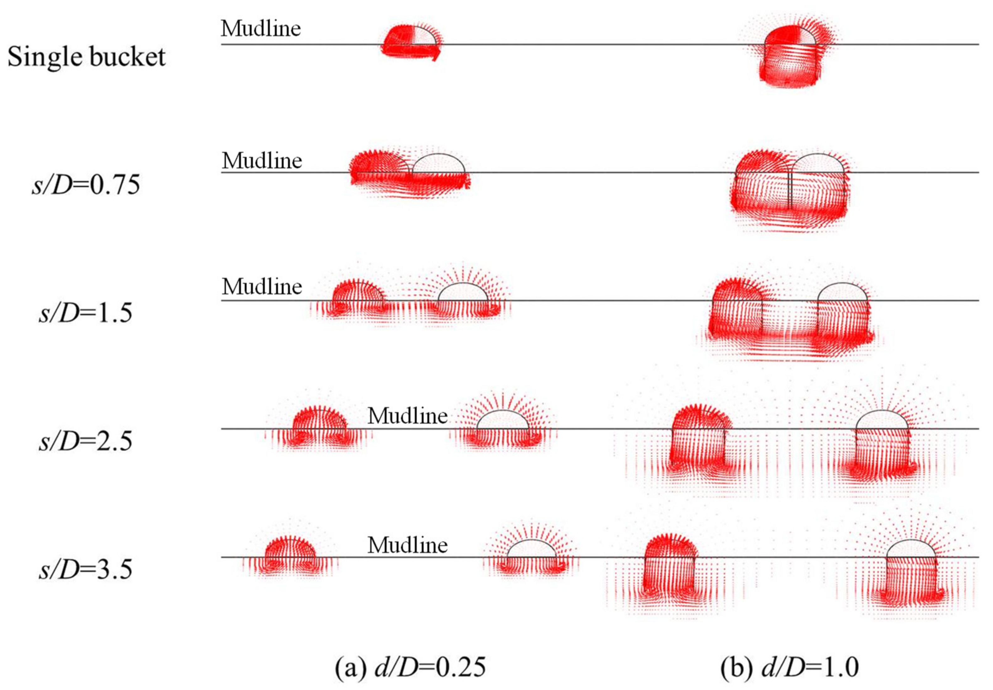
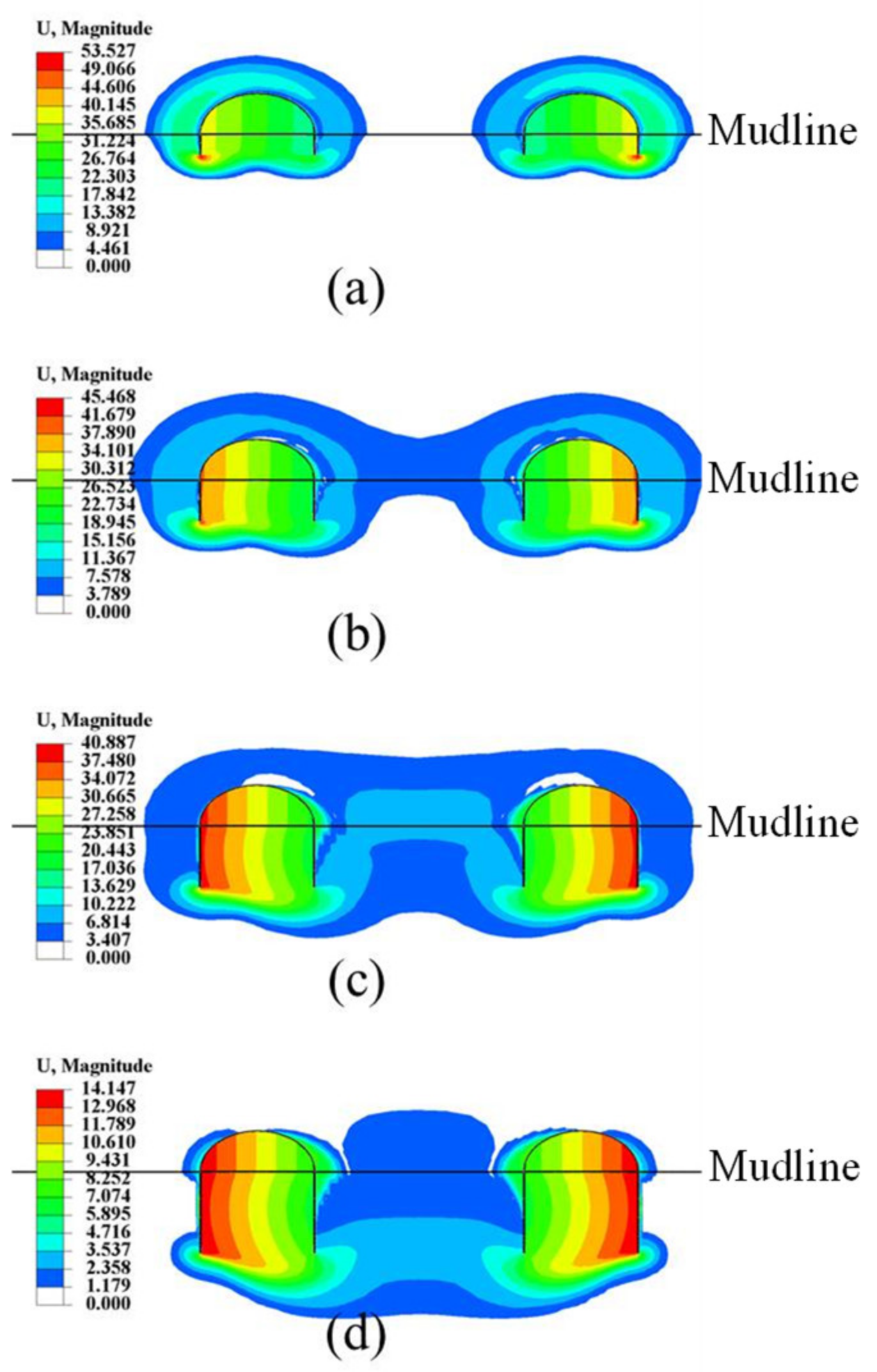
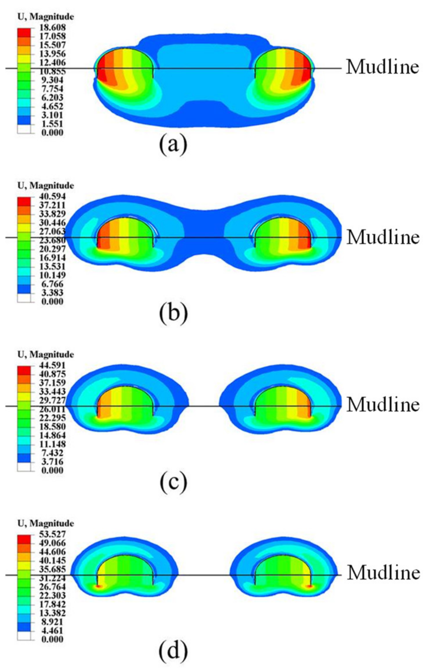
- The moment capacity factor of the tetrapod bucket foundations (NM) increases quite remarkably as s/D increases, and its enhancement is up to 27 fold when s/D = 3.5 and d/D = 0.25, compared to NM,s. Meanwhile, NM increases with the increase in d/D and decreases with the increase in κ. NM with a smaller d/D or larger κ enhances more significantly, compared to that of the single bucket foundation. The tetrapod bucket foundations and soils surrounded by them can be regarded as one foundation, which rotate around a point under ultimate moment loading when s/D is small, while its failure mode evolves into a push–pull failure mode at a large enough s/D. The uniaxial moment capacity of the tetrapod bucket foundations is influenced by s/D, d/D, κ and φ, and can be calculated through multiplying the moment capacity of the tetrapod bucket foundations in the push–pull failure mode (Mmax,pp) by the normalized moment group effect factor (FM).
- (4)
- The tetrapod bucket foundation has the largest vertical bearing capacity when s/D ≥ 3.5, while it has the maximum horizontal capacity when s/D ≥ 3.0. Failure mode of tetrapod bucket foundations evolves into a push–pull failure mode when s/D ≥ 3.0 to provide a good moment capacity. s/D = 3.5 is suggested to gain good capacities and a relatively high global stiffness for the tetrapod bucket foundations.
- (5)
- Systematic parametric studies are suggested to investigate the bearing-capacity envelopes and failure mechanisms of tetrapod bucket foundations under combined loadings in further studies.
Author Contributions
Funding
Institutional Review Board Statement
Informed Consent Statement
Data Availability Statement
Conflicts of Interest
Notation List
| A | Cross-sectional area of tetrapod bucket foundations |
| As | Cross-sectional area of a single bucket foundation |
| B | Width of tetrapod bucket foundations |
| d | Foundation embedment depth |
| D | Diameter of a single bucket foundation |
| E | Young’s modulus |
| EH | Horizontal group effect factor of tetrapod bucket foundations = NH/NH,s |
| EM | Moment group effect factor of tetrapod bucket foundations = NM/NM,s |
| EV | Vertical group effect factor of tetrapod bucket foundations = NV/NV,s |
| FH | Normalized horizontal group effect factor of tetrapod bucket foundations = NH/NHmax,s |
| FM | Normalized moment group effect factor of tetrapod bucket foundations = Mult/Mmax,pp |
| h | Horizontal displacement |
| H | Horizontal load |
| Hmax,s | Maximum horizontal capacity of a single bucket foundation |
| Hult | Uniaxial horizontal capacity of tetrapod bucket foundations |
| Hult,s | Uniaxial horizontal capacity of a single bucket foundation |
| k | Undrained soil shear strength gradient with depth |
| M | Moment |
| Mmax.pp | Moment capacity of tetrapod bucket foundations in push–pull failure mode |
| Mult | Uniaxial moment capacity of tetrapod bucket foundations |
| Mult,s | Uniaxial moment capacity of a single bucket foundation |
| NH | Horizontal capacity factor of tetrapod bucket foundations = Hult/Asu0 |
| NH,s | Horizontal capacity factor of a single bucket foundation = Hult,s/Assu0 |
| NHmax,s | Maximum horizontal capacity factor of a single bucket foundation = Hmax,s/Assu0 |
| NM | Moment capacity factor of tetrapod bucket foundations = Mult/ADsu0 |
| NM,s | Moment capacity factor of a single bucket foundation = Mult,s/AsDsu0 |
| NV | Vertical capacity factor of tetrapod bucket foundations = Vult/Asu0 |
| NV,s | Vertical capacity factor of a single bucket foundation = Vult,s/Assu0 |
| s | Separation distance between the center of each bucket and that of the tetrapod bucket foundation |
| su | Undrained shear strength of clay |
| sum | Undrained shear strength of clay at the ground surface |
| su0 | Undrained shear strength of clay at a specific depth (at depth D/4 below skirt tip level for tetrapod bucket foundations in this study) |
| v | Vertical displacement |
| V | Vertical load |
| Vult | Uniaxial vertical capacity of tetrapod bucket foundations |
| Vult,s | Uniaxial vertical capacity of a single bucket foundation |
| γ’ | Effective unit weight |
| θ | Rotation angle |
| κ | Soil-strength heterogeneity index |
| φ | The intersection angle between the load plane and symmetry plane of the tetrapod bucket foundations |
References
- Wang, X.; Zeng, X.; Li, J.; Yang, X.; Wang, H. A review on recent advancements of substructures for offshore wind turbines. Energy Convers. Manag. 2018, 158, 103–119. [Google Scholar] [CrossRef]
- Aubeny, C.; Murff, J.D. Simplified limit solutions for the capacity of suction anchors under undrained conditions. Ocean Eng. 2005, 32, 864–877. [Google Scholar] [CrossRef]
- Tani, K.; Craig, W.H. Bearing capacity of circular foundation on soft clay of strength increasing with depth. Soils Found. 1995, 35, 21–35. [Google Scholar]
- Tang, X.; Zhang, X.; Shao, Q.; Li, Z. Rotation center and horizontal bearing capacity of the bucket foundation in soft ground. Mar. Georesourc. Geotechnol. 2016, 34, 594–601. [Google Scholar] [CrossRef]
- Hu, Y.; Randolph, M.F.; Watson, P.G. Bearing response of skirted foundation on nonhomogeneous soil. J. Geotech. Geoenviron. 1999, 125, 924–935. [Google Scholar] [CrossRef]
- Bransby, M.F.; Yun, G. The undrained capacity of skirted strip foundations under combined loading. Géotechnique 2009, 59, 115–125. [Google Scholar] [CrossRef]
- Skau, K.S.; Jostad, H.P. Application of the NGI-procedure for design of bucket foundations for offshore wind farms. In Proceedings of the 24th International Ocean and Polar Engineering Conference, Busan, Korea, 15–20 June 2014. [Google Scholar]
- Byrne, B.W.; Cassidy, M.J. Investigating the response of offshore foundations in soft clay soils. In Proceedings of the 21st International Conference on Offshore Mechanics and Arctic Engineering, Oslo, Norway, 23–28 June 2002. [Google Scholar]
- Coffman, R.R.; El-Sherbiny, R.M.; Rauch, A.F. Measured horizontal capacity of suction caissons. In Proceedings of the Offshore Technology Conference, Houston, TX, USA, 3–6 May 2004. [Google Scholar]
- Houlsby, G.T.; Kelly, R.B.; Huxtable, J.; Byrne, B.W. Field trials of suction caissons in clay for offshore wind turbine foundations. Géotechnique 2005, 55, 287–296. [Google Scholar] [CrossRef]
- Le, C.; Ding, H.; Zhang, P. Prototype testing for the partial removal and re-penetration of the mooring dolphin platform with multi-bucket foundations. Mar. Struct. 2018, 59, 80–93. [Google Scholar] [CrossRef]
- Guo, Z.; Jeng, D.; Guo, W.; Wang, L. Failure mode and capacity of suction caisson under inclined short-term static and one-way cyclic loadings. Mar. Georesourc. Geotechnol. 2018, 36, 52–63. [Google Scholar] [CrossRef]
- Zhu, F.Y.; O’Loughlin, C.D.; Bienen, B.; Cassidy, M.J.; Morgan, N. The response of suction caissons to long-term lateral cyclic loading in single-layer and layered seabeds. Géotechnique 2018, 68, 729–741. [Google Scholar] [CrossRef]
- Wang, X.; Yang, X.; Zeng, X. Lateral capacity assessment of offshore wind suction bucket foundation in clay via centrifuge modelling. J. Renew. Sustain. Energy 2017, 9, 033308. [Google Scholar] [CrossRef]
- Barari, A.; Ibsen, L.B. Undrained response of bucket foundations to moment loading. Appl. Ocean. Res. 2012, 36, 12–21. [Google Scholar] [CrossRef]
- Taiebat, H.A.; Carter, J.P. Numerical studies of the bearing capacity of shallow foundations on cohesive soil subjected to combined loading. Géotechnique 2000, 50, 409–418. [Google Scholar] [CrossRef]
- Gourvenec, S.; Randolph, M.F. Effect of strength non-homogeneity on the shape of failure envelopes for combined loading of strip and circular foundations on clay. Géotechnique 2003, 53, 575–586. [Google Scholar] [CrossRef]
- Wang, D.; Jin, X. Failure loci of suction caisson foundations under combined loading conditions. China Ocean Eng. 2008, 22, 455–464. [Google Scholar]
- Feng, X.; Gourvenec, S.; Randolph, M.F. Optimal skirt spacing for subsea mudmats under loading in six degrees of freedom. Appl. Ocean. Res. 2014, 48, 10–20. [Google Scholar] [CrossRef][Green Version]
- Hung, L.C.; Kim, S.R. Evaluation of vertical and horizontal bearing capacities of bucket foundations in clay. Ocean Eng. 2012, 52, 75–82. [Google Scholar] [CrossRef]
- Vulpe, C. Design method for the undrained capacity of skirted circular foundations under combined loading: Effect of deformable soil plug. Géotechnique 2015, 65, 669–683. [Google Scholar] [CrossRef]
- Ukritchon, B.; Keawsawasvong, S. Undrained pullout capacity of cylindrical suction caissons by finite element limit analysis. Comput. Geotech. 2016, 80, 301–311. [Google Scholar] [CrossRef]
- Wu, K.; Fan, Q.; Zheng, J. Effect of strength anisotropy on failure envelope of offshore shallow foundations under combined loading. J. Coastal Res. 2015, 73, 521–526. [Google Scholar] [CrossRef]
- Xiao, Z.; Ge, B.; Wang, Y. Capacities and failure modes of suction bucket foundation with internal bulkheads. J. Ocean Univ. China 2017, 16, 627–634. [Google Scholar] [CrossRef]
- Masoumi Shahr-Babak, M.; Khanjani, M.J.; Qaderi, K. Uplift capacity prediction of suction caisson in clay using a hybrid intelligence method (GMDH-HS). Appl. Ocean Res. 2016, 59, 408–416. [Google Scholar] [CrossRef]
- Kim, Y.; Ahn, J.; Jung, J. Fuzzy modeling of holding capacity of offshore suction caisson anchors. Int. J. Numer. Anal. Methods Geomech. 2017, 41, 1038–1054. [Google Scholar] [CrossRef]
- Derakhshani, A. On the uncertainty analysis of uplift capacity of suction caissons in clay based on the fuzzy sets theory. Ocean Eng. 2018, 170, 416–425. [Google Scholar] [CrossRef]
- Stergiou, T.; Terzis, D.; Georgiadis, K. Undrained bearing capacity of tripod skirted foundations under eccentric loading. Geotechnik 2015, 38, 17–27. [Google Scholar] [CrossRef]
- Kim, S.R.; Hung, L.C.; Oh, M. Group effect on bearing capacities of tripod bucket foundations in undrained clay. Ocean Eng. 2014, 79, 1–9. [Google Scholar] [CrossRef]
- Hung, L.C.; Kim, S.R. Evaluation of combined horizontal-moment bearing capacities of tripod bucket foundations in undrained clay. Ocean Eng. 2014, 85, 100–109. [Google Scholar] [CrossRef]
- Liu, B.; Zhang, Y.; Ma, Z.; Andersen, K.H.; Jostad, H.P.; Liu, D.; Pei, A. Design considerations of suction caisson foundations for offshore wind turbines in Southern China. Appl. Ocean Res. 2020, 104, 102358. [Google Scholar] [CrossRef]
- Zhu, B.; Dai, J.; Kong, D.; Feng, L.; Chen, Y. Centrifuge modelling of uplift response of suction caisson groups in soft clay. Can. Geotech. J. 2020, 57, 1294–1303. [Google Scholar] [CrossRef]
- API. RP 2GEO Geotchnical and Foundation Design Considerations, 1st ed.; Americal Petroleum Institute: Washington, DC, USA, 2011. [Google Scholar]
- DNVGL. RP E303, Geotechnical Design and Installation of Suction Anchors in Clay; DNVGL: Oslo, Norway, 2017. [Google Scholar]
- Dassault Systemes. Abaqus User’s Manual, Version 6.13; Simula Corp: Providence, RI, USA, 2013. [Google Scholar]
- Gao, F.; Wang, N.; Zhao, B. Ultimate bearing capacity of a pipeline on clayey soils: Slip-line field solution and FEM simulation. Ocean Eng. 2013, 73, 159–167. [Google Scholar] [CrossRef]
- Feng, X.; Randolph, M.F.; Gourvenec, S.; Wallerand, R. Design approach for rectangular mudmats under fully three dimensional loading. Geotechnique 2014, 64, 51–63. [Google Scholar] [CrossRef]
- Fu, D.; Bienen, B.; Gaudin, C.; Cassidy, M. Undrained capacity of a hybrid subsea skirted mat with caissons under combined loading. Can. Geotech. J. 2014, 51, 934–949. [Google Scholar] [CrossRef]
- Li, J.; Zhou, Y.; Zhang, L.; Tian, Y.; Cassidy, M.; Zhang, L. Random finite element method for spudcan foundations in spatially variable soils. Eng. Geol. 2016, 205, 146–155. [Google Scholar] [CrossRef]
- Vulpe, C.; Gourvenec, S.; Power, M. A generalised failure envelope for undrained capacity of circular shallow foundations under general loading. Géotech. Lett. 2014, 4, 187–196. [Google Scholar] [CrossRef]
- Xiao, Z.; Tian, Y.; Gourvenec, S. A practical method to evaluate failure envelopes of shallow foundations considering soil strain softening and rate effects. Appl. Ocean Res. 2016, 59, 395–407. [Google Scholar] [CrossRef]
- Houlsby, G.T.; Wroth, C.P. Calculation of stresses on shallow penetrometers and footings. In Proceedings of the IUTAM/IUGG Symposium on Seabed Mechanics, Tyne, UK, 5–9 September 1983; Springer: Dordrecht, The Netherlands; Newcastle, UK, 1983. [Google Scholar]
- Wang, J. A Study on Bearing Capacity Behaviour of Bucket Foundations under Combined Loading in Soft Clay; Tianjin University Press: Tianjin, China, 2012. (In Chinese) [Google Scholar]
- Hung, L.C.; Kim, S.R. Evaluation of undrained bearing capacities of bucket foundations under combined loads. Mar. Georesourc. Geotechnol. 2014, 32, 76–92. [Google Scholar] [CrossRef]


| κ | NV,s | NH,s | NM,s | |||
|---|---|---|---|---|---|---|
| This Study | Exact Solutions [42] | This Study | Exact Solutions (NH,s = 1.0) | This Study | Solutions [17] | |
| 0 | 5.91 | 6.05 | 1.06 | 1.00 | 0.74 | 0.67 |
| 1 | 6.81 | 6.95 | 1.06 | 1.00 | 0.86 | 0.78 |
| 2 | 7.50 | 7.63 | 1.06 | 1.00 | 0.97 | 0.88 |
| 6 | 9.65 | 9.67 | 1.07 | 1.00 | 1.33 | 1.24 |
| 10 | 11.42 | 11.33 | 1.07 | 1.00 | 1.67 | 1.58 |
| s/D | κ | θ (°) | |||
|---|---|---|---|---|---|
| d/D = 0.25 | d/D = 0.5 | d/D = 0.75 | d/D = 1.0 | ||
| 0.75 | 0 | 0.06 | 0.18 | 0.68 | 8.50 |
| 2 | 0.03 | 0.10 | 0.32 | 2.27 | |
| 10 | 0.02 | 0.08 | 0.26 | 1.87 | |
| 1.0 | 0 | 0.04 | 0.13 | 0.37 | 1.93 |
| 2 | 0.02 | 0.07 | 0.18 | 1.09 | |
| 10 | 0.02 | 0.06 | 0.15 | 0.90 | |
| 1.25 | 0 | 0.03 | 0.11 | 0.29 | 1.30 |
| 2 | 0.01 | 0.05 | 0.14 | 0.68 | |
| 10 | 0.01 | 0.04 | 0.11 | 0.54 | |
| 1.5 | 0 | 0.03 | 0.09 | 0.24 | 1.00 |
| 2 | 0.01 | 0.04 | 0.11 | 0.44 | |
| 10 | 0.01 | 0.03 | 0.08 | 0.32 | |
| 2.0 | 0 | 0.01 | 0.05 | 0.13 | 0.44 |
| 2 | 0.01 | 0.02 | 0.06 | 0.16 | |
| 10 | 0.00 | 0.02 | 0.04 | 0.11 | |
| 2.5 | 0 | 0.01 | 0.03 | 0.09 | 0.24 |
| 2 | 0.00 | 0.01 | 0.04 | 0.08 | |
| 10 | 0.00 | 0.01 | 0.03 | 0.06 | |
| 3.0 | 0 | 0.01 | 0.02 | 0.06 | 0.16 |
| 2 | 0.00 | 0.01 | 0.03 | 0.06 | |
| 10 | 0.00 | 0.01 | 0.02 | 0.04 | |
| 3.5 | 0 | 0.00 | 0.01 | 0.04 | 0.10 |
| 2 | 0.00 | 0.01 | 0.02 | 0.04 | |
| 10 | 0.00 | 0.01 | 0.02 | 0.03 | |
Publisher’s Note: MDPI stays neutral with regard to jurisdictional claims in published maps and institutional affiliations. |
© 2022 by the authors. Licensee MDPI, Basel, Switzerland. This article is an open access article distributed under the terms and conditions of the Creative Commons Attribution (CC BY) license (https://creativecommons.org/licenses/by/4.0/).
Share and Cite
Xiao, Z.; Wang, Y.; Liu, Y.; Tian, Y.; Wang, R.; Tao, R.; Wei, X. Formulas for Uniaxial Capacities of Tetrapod Bucket Foundations Considering Group Effects in Undrained Clay. Appl. Sci. 2022, 12, 5353. https://doi.org/10.3390/app12115353
Xiao Z, Wang Y, Liu Y, Tian Y, Wang R, Tao R, Wei X. Formulas for Uniaxial Capacities of Tetrapod Bucket Foundations Considering Group Effects in Undrained Clay. Applied Sciences. 2022; 12(11):5353. https://doi.org/10.3390/app12115353
Chicago/Turabian StyleXiao, Zhong, Yan Wang, Ying Liu, Yinghui Tian, Rong Wang, Ran Tao, and Xian Wei. 2022. "Formulas for Uniaxial Capacities of Tetrapod Bucket Foundations Considering Group Effects in Undrained Clay" Applied Sciences 12, no. 11: 5353. https://doi.org/10.3390/app12115353
APA StyleXiao, Z., Wang, Y., Liu, Y., Tian, Y., Wang, R., Tao, R., & Wei, X. (2022). Formulas for Uniaxial Capacities of Tetrapod Bucket Foundations Considering Group Effects in Undrained Clay. Applied Sciences, 12(11), 5353. https://doi.org/10.3390/app12115353