Abstract
This research assessed a mechanical coupling for the ISOFIX Child Restraint System using the Finite Element Method (FEM) in a critical condition (simultaneous frontal and lateral collision). The mechanism was designed according to the R129 standard, and it consists of a set of springs and dampers that allows displacements in the three Cartesian axes (x, y, z) to dissipate a portion of the energy produced by a traffic accident. Two case studies are presented. The first one evaluates the behavior of the mechanism by applying the equivalent weight of a child and the LBB during a frontal and lateral impact according to the FMVSS 213 standard. The second evaluates the injuries generated in the head, neck, and thorax with a six-year Hybrid III model during a frontal impact when implementing the coupling system. The outcomes show that both axes reach a maximum deceleration of 23 G, and it remains from 17 G to 21 G in 30 ms. After 65 ms, it decreases from 17 G to 0 G. Overall, the injury rates are compared when using mechanical coupling with LBB and only LBB to analyze the system’s efficiency, showing a significant reduction in head and neck injuries, obtaining a 24% variation in the HIC36, and reducing the neck range motion by 19.3°.
1. Introduction
In 2018, around 1038 children died in motor vehicle traffic crashes in the USA. It was also estimated that 190,000 children were injured. Of the 1038 children in motor vehicle accidents, 797 were occupants, and the rest were non-occupants (pedestrians, cyclists, and others). Child safety seats have been shown to reduce fatal injury by 71% for infants under one year old and 54% for toddlers (1 to 4 years old) in passenger cars [1]. The child restraint system (CRS) aims to protect the infant according to weight and age in case of a car accident. In addition, the manufacturers include instructions for the correct use of the CRS [2]. However, from a statistic where 285 infants used a CRS, 22.2% implemented it poorly. The most recurrent error was an inadequate selection of the CRS class, followed by inadequate positioning of the CRS infant and incorrect orientation [3]. The American Pediatric Association recommends the use of low-back boosters (LBBs) for children aged 4–8 years or weighing 18–36 kg [4], and the International Organization for Standards (ISO) 13216 describes a universal system for anchoring a CRS named ISOFIX. This standard specifies the general dimension requirements for rigid anchors for CRS in vehicles.
A rigid anchor system holds the child seat directly to the vehicle’s body [5]. Statistical data from frontal crashes showed that the most frequent injury in infants was to the head. However, since a small child has a large head mass and a fragile neck structure, the neck loading may cause a severe or fatal injury [6]. The neck usually experiences the inertial load generated by the head; during the initial phase of the shock, more restriction is applied to the lower neck, while the head is usually subject to a horizontal translation displacement of the torso, which induces neck extension movements. The neck is exposed to significant mechanical loads when the natural range of extension and flexion of the neck is reached, causing elongation and even tearing in different ligaments, leading them to an extreme point of the anterior dislocation of the joints [7]. There are designs of coupling systems for CRS that provide additional protection to the infant, dissipating the child’s kinetic energy and the CRS during the crash. One of them is the vehicle seat interlock system, which consists of an interlock mechanism between a seatback latching mechanism and a child seat latching mechanism. The interlock mechanism allows the child seat to be deployed when the seat back is in its typical upright and latched condition [8]. In 1977, a system was designed consisting of compressible shock absorber assemblies and friction coupling portions, which absorbed some of the kinetic energy of the vehicle impact through the sliding movement of the CRS about the support bars and the vehicle seat, which was named an apparatus with a child seat and an energy absorption mechanism [9]. In 1980, a modified CRS called child’s safety seat for vehicles consisted of a seat mounted on a frame adapted to the structure to allow for rotational movement and maintain the center of gravity of the seat with the infant below the means of pivoting [10]. In 2015, a new design called “Crash indication system for a reclining ride down child seat” consisted of a base to support the lower part of the CRS, which allowed the CRS to move on itself depending on the magnitude of the external force applied. A ratchet connection prevented the carriage from returning to its resting position [11].
Some variants of designs or systems for mounting a CRS provide additional protection for infants. However, those systems only fulfill their function under frontal impact conditions. A coupling device for a CRS allows displacement and the dissipation control of kinetic energy during the vehicular impact in a traffic accident. This research aims to evaluate the behavior and performance of a CRS mechanical coupling with ISOFIX during a lateral and frontal impact. Furthermore, the injuries generated in the Hybrid III six-year-old (6YO) when the mechanical coupling is implemented and when only the LBB is used are compared. The LBB analysis is compared with experimental tests [12]. This work is organized as follows: The parts used to perform the numerical simulation, their mechanical properties, and the boundary conditions are established. The results compare the kinematic variables and the injuries generated in the neck, head, and thorax when implementing the mechanical coupling with LBB and when not implementing it. The Conclusions section shows the seat belt efficiency during infant retention.
2. Materials and Methods
The mechanism was designed according to the R129 standard [13]. The mechanism aims to dissipate the impact energy generated by a traffic accident transferred to the infant. The mechanism was made with a set of springs and dampers since they do not depend on an external energy source to activate, and the speed response is satisfactory, allowing displacement in the 3 Cartesian axes (x, y, z) [14,15,16]. The components and dimensions of the mechanism were generated by SolidWorks® software and are divided into two parts: the Cartesian mechanism box and the suspension box, as is shown in Figure 1.
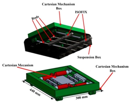
Figure 1.
Mechanical coupling.
The Cartesian mechanism box contains eight springs for the x-axis and four for the y-axis, plus two shock absorbers for each axis. Two mass concentrators were added to allow the system to dissipate some of the kinetic energy in the x-axis. The suspension box consists of two shock absorbers and two springs assembled with the Cartesian mechanism box. Their function is to dissipate energy in the z-axis, modify anchored orientation to the vehicle seat, and adapt the CRS according to the child’s age. This is achieved through three L-shaped rods. Two are placed in the same direction, and one is oriented in the opposite direction. The locks are designed in such a way that the rod presses the lock with its shorter part, while the longer part is the one that penetrates the suspension box, allowing for changing the orientation of the anchors. The mechanical coupling contains a rail (T) that allows mass concentrator displacement (M1 and M2) and the bearing on which the CRS (C) is mounted on the x-axis. T is fixed to the bearings (J1 and J2) to allow displacement along the y-axis. These displacements occur within the Cartesian mechanism box, as shown in Figure 2.
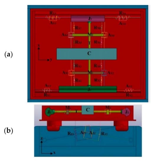
Figure 2.
Distribution of springs and dampers in mechanical coupling, (a) Top view (b) frontal view.
2.1. Boundary Conditions
2.1.1. Case 1
Numerical analysis was performed using LS-Dyna® software, attaching each of the springs and dampers of the system, which were established based on commercial catalogs [17,18] mentioned in Table 1, a rail (T) that allows the displacement of the mass concentrators (M1 and M2), and the bearing on which the CRS is mounted (C) on the x-axis. In addition, the rail would be fixed to the bearings (J1 and J2), which allow movement along the y-axis (Figure 2). Bearing C has a mass of 30 kg, equivalent to 6.6 kg of the CRS plus 23.4 kg of the Hybrid III 6-year-old infant numerical model.

Table 1.
Constants and dimensions of springs and dampers belonging to the mechanical coupling.
Subsequently, parts were entered into the HyperMesh® V.14.0 (Troy, MI, USA) software to perform the discretization of each, with hexahedral elements (8 nodes) of 4 mm, as shown in Figure 3.
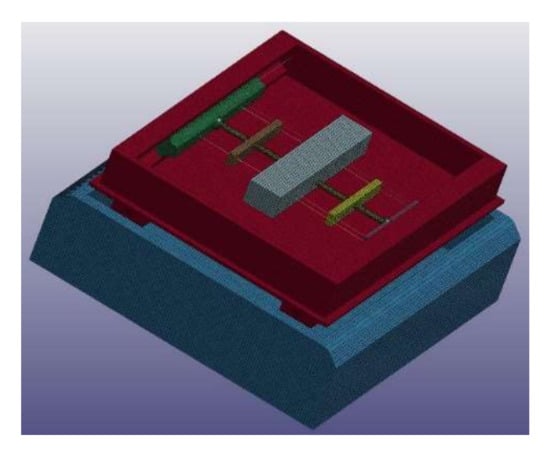
Figure 3.
Meshing with 4 mm hexahedra (8 nodes) elements.
For the Cartesian mechanism box, suspension box, J1, J2, C, and T, the mechanical properties are set as: aluminum 1100-H14 density of 2.71 × 10⁻⁶ kg/mm3, Young’s modulus of 70 GPa, an elastic limit of 0.095 GPa, and Poisson’s ratio of 0.33 [19]. For M1 and M2, properties are those of A36 structural steel: density of 7.85 × 10⁻⁶ kg/mm3, Young’s modulus of 200 GPa, an elastic limit of 0.25 GPa, and Poisson’s ratio of 0.32 [20]. The initial system speed is 13.34 m/s on the +x and +y-axes. The deceleration peak in the −x and −y directions are taken from the FMVSS 213 regulation for frontal impact (Figure 4) [21]. The same peak is used in both directions to obtain values on its performance under critical situations. The suspension box decelerates, as is shown in Figure 4. Its movement on the z-axis is restricted to simulate that its placement on the vehicle’s rear seat with ISOFIX anchorage. Additionally, a translational joint from the suspension box to the Cartesian mechanism box was implemented. In this way, the Cartesian mechanism box will move along the z-axis concerning the suspension box. Gravity acts on the axis −z with a constant value of 0.00981 mm/ms2.
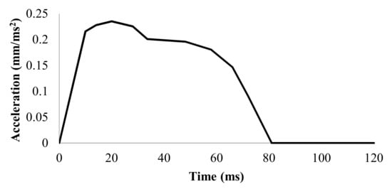
Figure 4.
Deceleration curve for frontal impact.
2.1.2. Case 2
The analysis was performed with the Hybrid III 6YO FEM dummy [22] to obtain the possible injuries generated in the infant during a frontal crash test. A controlled mesh was used with 8 mm hexahedra (8 nodes) for each of the designed pieces and 8 mm 2D quadratic (4 nodes) elements for the seat belt located on the chest and pelvis to maintain continuity of the nodes. The contacts established are back seat-dummy, LBB-dummy, seat belt-dummy, and C-LBB, and a static coefficient of 0.3 and a dynamic coefficient of 0.2 are defined [23]. In addition, the suspension box is fixed to the rear seat for the mechanical coupling, and a common type of translation is implemented to allow displacement along the z-axis between the suspension box and the Cartesian mechanism box.
The rear seat and 3-point seat belt (3p) were designed with the 2010 Toyota® Yaris vehicle’s dimensions. The rear seat consists of steel support, padding, and a polypropylene connector between the seat back and the seat cushion part. The seat belt was designed in LS-DYNA® software using one- and two-dimensional elements. The LBB design is based on the Evenflo® model belonging to groups 2 and 3 (adjustable for 3–11 years or 18–49.8 kg). It consists of support material, which, in this case, is polypropylene and padding. The mechanical coupling was designed according to the R129 standard, allowing it to be correctly adjusted to the car seats and implemented in existing CRSs in the international market [13].
Polypropylene mechanical properties were used for the LBB and connector with the backrest. The rear seat cushions have a density of 9 × 10⁻⁷ kg/mm3, Young’s modulus of 1.35 GPa, yield strength of 0.036 GPa, and Poisson’s ratio of 0.3 [24]. Foam DAX 55 was selected, whose mechanical properties are: density of 3.5 × 10⁻⁸ kg/mm3, Young’s modulus of 5 × 10⁻⁵ GPa, Poisson’s ratio of 0.31 LBB, and vehicle rear seat cushions [25]. For this type of material, it is necessary to add the stress–strain curve [26]. In the Cartesian mechanism box, suspension box, J1, J2, C, and T parts, the mechanical properties of aluminum 1100-H14 are used: density of 2.71 × 10⁻⁶ kg/mm3, Young’s modulus of 70 GPa, an elastic limit of 0.095 GPa, and Poisson’s ratio of 0.33 [20]. As for M1 and M2, A36 structural steel is used: density of 7.85 × 10⁻⁶ kg/mm3, Young’s modulus of 200 GPa, an elastic limit of 0.25 GPa, and Poisson’s ratio of 0.32 [21]. The seat belt made by one-dimensional elements is 5.97 × 10⁻⁴ kg/mm [27]. The mechanical properties of Nylon were implemented for the two-dimensional elements: density of 1 × 10⁻⁶ kg/mm3, Young’s modulus of 5.333 GPa, an elastic limit of 0.08 GPa, and Poisson’s ratio of 0.3. Load and unload curves representing the axial force as a seat belt function were used [28]. The assembly of all parts that were set up in the analysis was maintained in LS-DYNA® software, as shown in Figure 5.
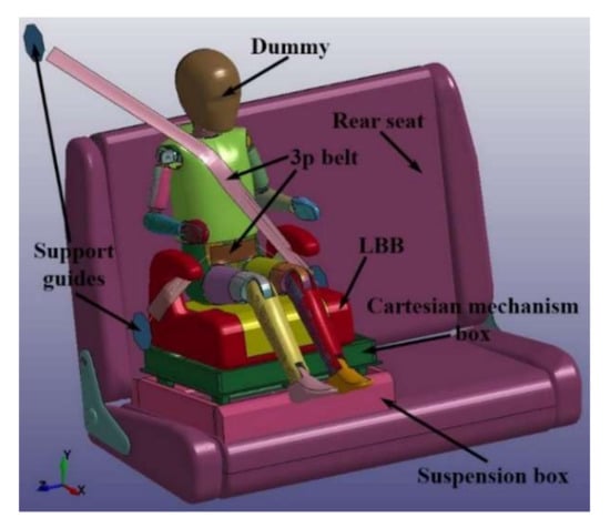
Figure 5.
Frontal impact scenario assembly.
3. Results
3.1. Coupling System Findings
The results obtained from the coupling system showed that the simulated period was 1000 ms, and data were obtained every 1 ms. The piece of interest is C in the system. The assessed displacement values within the Cartesian mechanism box on the x-, y-, and z-axes during the analyzed interval are shown in Figure 6.
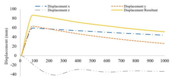
Figure 6.
Displacement of C inside Cartesian mechanism box.
It can be seen that C moves 63 mm on the y-axis and 60 mm on the x-axis. This distance is what the system needs to dissipate the energy caused by the impact so that it later begins to return to its original point. However, it will take more than 1000 ms to reach equilibrium. It should be noted that side impacts are less abrupt than frontal impacts. The 41 mm displacement in the z-axis is carried out in the negative direction since the system descends due to the exerted force added by gravity. The peak is smoother because the deceleration is not as sudden as in the x- and y-axes.
The coupling response after 100 ms of deceleration is maintained at 0 G. Decelerations are shown during the first 120 ms, as seen in Figure 7.
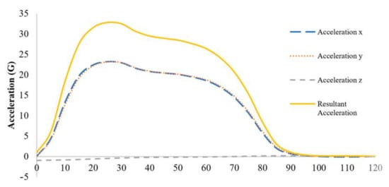
Figure 7.
Acceleration of C.
The deceleration of x and y are similar since the curve in Figure 4 was implemented for both axes. Both axes obtain a maximum deceleration of 23 G, and it remains from 21 G to 17 G for 30 ms. After 65 ms, it decreases from 17 G to 0 G. In the z-axis, it is observed that it begins at 1 G; the gravity acceleration is set on the axis -z, and the system counteracts the gravitational acceleration in 31 ms, which becomes 0 G.
The Cartesian mechanism box, spring interconnections, and dampers are the most critical areas in Figure 8.
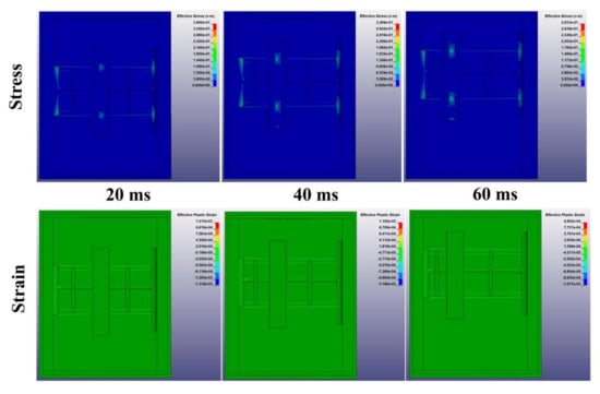
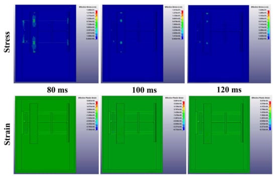
Figure 8.
Cartesian Mechanism Stress and Strain.
The resulting acceleration reaches a maximum value of 33 G. The stresses (using Von Mises’ failure theory) and strains of each mechanism’s parts during the first 120 ms are obtained. The values are plotted every 20 ms of the Cartesian mechanism; this part records the mechanism’s highest values of stress and strain (Figure 8).
The C part has the highest stress with 94 MPa; the stress of the Cartesian mechanism box is 92 Mpa, that of the suspension box is 68 MPa, and the M1 and M2 parts have the lowest stress in the first 120 ms. The mechanical properties of the material, knowing that it has an elastic limit of 95 MPa, guarantee that the parts of the mechanism work in the elastic zone since they do not exceed the yield point (Figure 9).
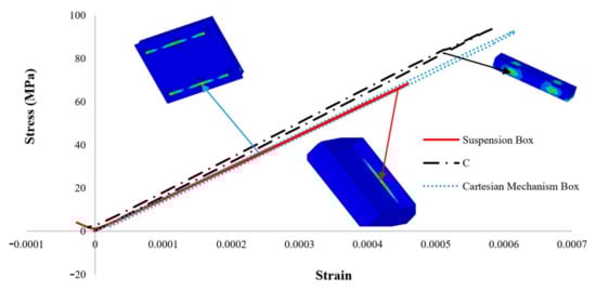
Figure 9.
Stress–strain curve of the coupling system.
3.2. Kinematic Behavior of Coupling System with LBB and without LBB
Furthermore, the results from the numerical simulations for case 2 were obtained in 120 ms, and data were obtained every 1 ms.
The analysis sequence in lateral view is shown for the frontal crash. It starts at t = 0 ms, and the end of the simulation is at t = 120 ms (Figure 10).
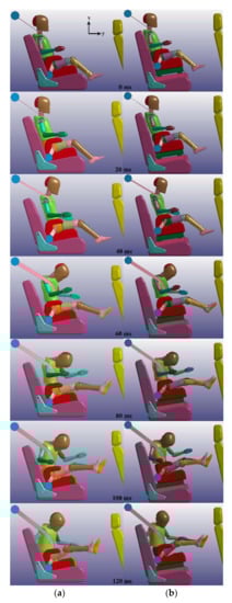
Figure 10.
Dummy kinematic results: (a) LBB by Cruz et al. [12]; (b) mechanical coupling with LBB.
3.2.1. Head Behavior Using the Coupling System
The accelerometer located in the center of gravity of the head’s dummy recorded accelerations every 1 ms during the 120 ms in which the frontal impact analysis was performed.
The values obtained by Cruz et al. show that the resulting acceleration of the head increases earlier for the LBB, starting at 23 ms, increasing from 2 G to 34 G in 3 ms. At 38 ms, an acceleration of 57 G is reached, and at 62 ms, the maximum acceleration of 62 G is achieved, generating a Head Injury Criterion HIC36 of 554.3. In the mechanical coupling with LBB, due to the movement that the system allows, the acceleration remains below 10 G during the first 24 ms, and from this point onwards, it begins to increase until it reaches 20 G in 9 ms. The maximum acceleration is achieved at 53 ms, reaching a value of 53 G and obtaining a HIC36 of 421.5, relative to 9 G. The LBB shows the maximum value and a difference in the HIC36 of 132.8 (Figure 11).
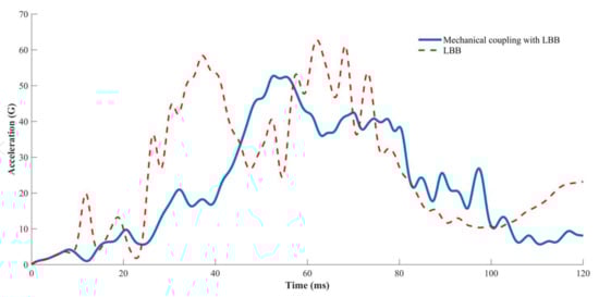
Figure 11.
Head acceleration.
3.2.2. Neck Behavior Using the Coupling System
Similarly, the rotational movement was obtained in degrees for the neck’s base using the accelerometer in the head’s center of gravity.
When implementing the LBB, flexion–extension is generated in the neck, reaching the maximum value of flexion at 88.3° at 67 ms, while the maximum value of extension recorded is −18° at 120 ms, considering an initial position of the neck of 0°, positive flexion, and harmful extension. When the mechanical coupling with LBB is used, only neck flexion occurs, with a maximum value of 87°, that is, 1.3° less than when only the LBB is used. The neck remains flexed and decreases by 49°, while with the LBB, there is a difference of 106.3° during the recoil (Figure 12).
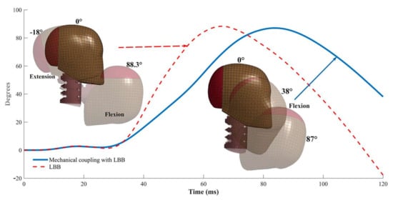
Figure 12.
Neck flexion and extension.
The neck injury criteria Nij obtained in both systems show that both remain within the NHTSA’s critical values.
The LBB generates a higher injury rate, causing tension of 2162 N and a deflection of 63.2 Nm. Therefore, when implementing the mechanical coupling with LBB, the flexion and extension are kept below 20 Nm, and the maximum stress is 371.5 N (Figure 13).
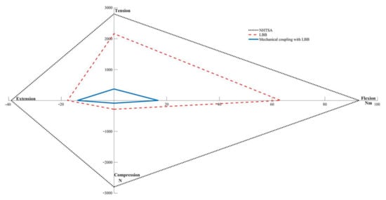
Figure 13.
Neck injury criteria (Nij).
3.2.3. Thorax Behavior Using the Coupling System
In the thoracic spine accelerations, the first 7 ms of the LBB and that of the mechanical coupling with LBB have similar behavior.
The LBB begins to increase the acceleration from 3 G at 7 ms until reaching the maximum acceleration of 47 G at 29 ms and descends to 14 G at 54 ms, and then there is an increase to 26 G at 61 ms, which begins to descend to 8 G at 120 ms. As a result, it generates a Chest Severity Index (CSI) of 281.9. On the other hand, implementing the mechanical coupling allows an initial displacement, causing the acceleration to start from 3.6 G at 14.6 ms until reaching the maximum acceleration of 60.8 G at 44 ms. After that, it decreases to 37 G at 48 ms, increases again to 46 G at 52 ms, and decreases to 16.2 G at 120 ms, generating a CSI of 375.6 (Figure 14).
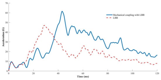
Figure 14.
Thoracic spine acceleration.
Both systems have similar behavior. During the first 14 ms, both systems generate the same thoracic spine deflections.
At 30 ms and 33 ms, they cause the same thoracic spine deflections of 22 mm and 33 mm, respectively. The LBB generates a maximum 44.7 mm thoracic spine deflection at 60 ms, dropping to 24.3 mm at 120 ms. The mechanical coupling with LBB generates a maximum thoracic spine deflection of 45.6 mm, remaining constant from 54 ms to 80 ms and decreasing to 25.8 mm at 120 ms (Figure 15).
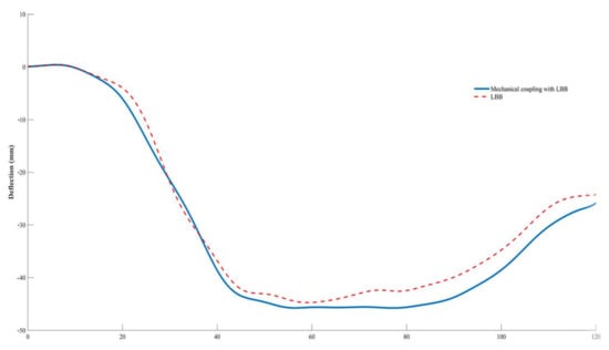
Figure 15.
Thoracic spine deflection.
4. Discussion
Most conventional CRSs do not have a cushioning system, and when the seat belt exerts enough pressure to prevent the infant from moving, it can cause injury to the infant. The commercial CRS that includes a cushioning system to provide additional protection to the infant only works in frontal impacts. Some systems have a mechanism that works until a force threshold is reached, with the probability of not being reached and remaining inactive during the impact. Other damping systems are complicated, with mechanical components that are too small, which increases their cost and failure. The proposed coupling mechanism mainly comprises springs and dampers to protect during frontal, rear, and side impacts since it works on the three Cartesian axes. Therefore, it is necessary to perform numerical analyses of the system with a CRS and an infant riding correctly in the rear seat of the vehicle to obtain data on the decelerations suffered by the infant, as well as possible injuries in the most critical areas, such as the neck, chest, and head, to compare with analyses that do not include the system, and to find injury variations. The analyses must be carried out under frontal, rear, lateral, and side-impact scenarios. A comparison was made with the low-back booster (LBB) deceleration obtained under the frontal impact scenario [11] concerning the deceleration of part C of the system on the x-axis (Figure 16).
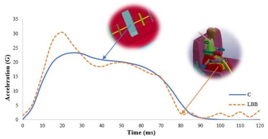
Figure 16.
Acceleration comparison using the coupling system.
Figure 16 shows that part C of the system minimizes deceleration and smooths the curve. A maximum deceleration of 22.5 G is obtained in C and 30.5 G in LBB, that is, a variation of 8 G. After 50 ms, C remains at 0 G, while the LBB keeps oscillating at 2.5 G. The variation is because the system dissipates part of the impact energy, transmitting less energy to the infant.
The values obtained from the numerical analysis with the mechanical coupling with LBB were compared with the analyses carried out by Cruz et al., allowing us to know the performance when implementing the system. It is worth mentioning that both the LBB and the mechanical coupling with LBB are below the NHTSA’s injury threshold. However, a remarkable reduction in head and neck injuries was caused by the infant’s decelerations during a frontal impact. This is because the mechanical coupling with LBB allows displacement in its three Cartesian axes to dissipate part of the energy caused by the impact, regardless of the direction in which the impact occurs. During the frontal impact, there is a displacement on the y-axis; it is kept at 0 during the first 20 ms, and later it oscillates between 1.3 mm and 2 mm, with 2 mm being the maximum displacement. In the z-axis, the displacement is mainly caused by the system’s weight and the dummy, obtaining a maximum displacement of 22.5 mm. Therefore, the energy of the frontal impact is mainly on the x-axis. Therefore, the system and the seat belt must minimize this energy to reduce injuries generated in the infant. The system allows a maximum displacement of 36.5 mm at 81 ms and begins to descend to 33.1 mm at 120 ms (Figure 17).
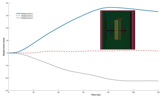
Figure 17.
Coupling Mechanical Displacement with LBB.
The seat belt retention with the LBB generates an acceleration of 9.3 G with a displacement of 27 mm, and at 93 mm, it begins to increase the acceleration until it reaches the maximum value of 47 G with a displacement of 360 mm. When the dummy is separated by 360 mm from the rear seat, the seat belt retains it, generating an acceleration of 47 G. When this occurs, the dummy continues a displacement of 152 mm to decrease the acceleration. The implementation of the mechanical coupling with LBB allows the dummy to have a more significant displacement, so it generates an acceleration of less than 9.5 G during the first 352 mm and then begins to increase the acceleration to 20 G at 420 mm; however, decreasing the acceleration to 17 G at 494 mm begins the retention, generating a maximum acceleration of 52 G with a displacement of 572 mm. The displacement reached by the system on the x-axis of 36.5 mm requires decreasing the acceleration to 52 G (Figure 18).
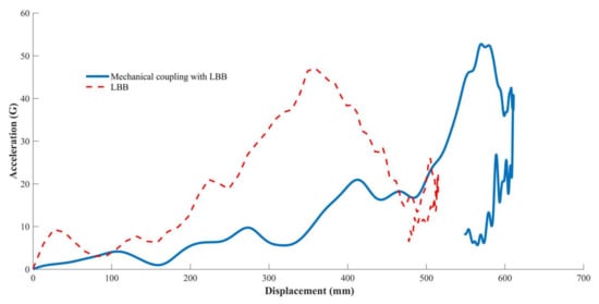
Figure 18.
Effectiveness of restraint systems.
5. Conclusions
The function performed by the device is essential since it is possible to reduce the accelerations suffered by the infant during a traffic accident, regardless of the type that occurs (front, rear, or side). This allows for minimizing the possibility of injury or reducing the severity. Therefore, the size and constant selection of the shock absorbers and springs are vital for the system’s optimal performance. The material selected for the device’s manufacture is suitable for allowing the system to keep working in its elastic zone. This guarantees that the device will not suffer plastic deformations, which would cause the movements of the pieces to be affected by breakage, causing the system’s failure. The system works correctly on the three Cartesian axes, and it takes 60 mm of displacement to counteract the decelerations produced by the frontal impact at a speed of 13.34 m/s. The selected springs and dampers were adequate for the correct performance of the system. Due to the performance of the cushioning system and with a CRS suitable for the infant, the pressure exerted by the retention system will be less, reducing the risk of fractures and injuries. With a device demonstrating the values obtained in this research, the protection of infants will be increased.
The LBB allows the seat belt to fit the infant properly, and the ISOFIX system allows the LBB to be anchored correctly in the vehicle. Tests show that it provides adequate protection to the infant during a frontal impact; however, implementing the mechanical coupling with LBB improves the infant’s protection, mainly reducing head and neck injuries, which are the most frequent injuries in this type of accident. By implementing the mechanical coupling with LBB, the maximum acceleration of the infant’s head is reduced by 9 G, generating a lower HIC36, with a variation of 132.8. The neck has a reduced range of motion of 19.3°, preventing extension and reducing neck tension by 1790.5 N. The mechanism’s displacements increase the acceleration of the thorax by 13.8 G since the belt generates a more significant thoracic pressure to retain the infant. Obtaining a higher CSI of 93.7 resulted in an increase of 0.9 mm in the thoracic spine deflection. The mechanism increases thoracic lesions; however, it is not significantly increased, as the increase in thoracic deflection is less than 1 mm. Instead, a decrease in HIC36 of 24% is obtained. The seat belt has better efficiency during the infant’s retention when the system is implemented, allowing a displacement of 36.5 mm to retain the infant, improving efficiency during retention by 24%. The device is essential since it allows the dissipation of part of the kinetic energy that the infant is subjected to during the frontal impact. As a result, the seat belt retention efficiency is improved; however, this results from an increase of 0.9 mm in the thoracic deflection. The device is essential to dissipate a part of the kinetic energy during a frontal impact on the LBB and to realize M1 and M2 oscillations. Therefore, the size and constant selection of the shock absorbers and springs are vital for the system’s optimal performance.
6. Patents
MX/a/2019/006717 “Adaptative Device For Vehicular Child Restraint Systems For Infants With Osteogénesis Imperfecta”; Submitted on 20 August 2019.
Author Contributions
Conceptualization, C.R.T.-S. and I.L.C.-J.; methodology, C.R.T.-S.; software, I.L.C.-J.; validation, C.R.T.-S. and L.M.-S.; formal analysis, I.L.C.-J.; investigation, L.M.-S.; resources, C.R.T.-S.; data curation, L.M.-S.; writing—original draft preparation, I.L.C.-J.; writing—review and editing, C.R.T.-S.; visualization, L.M.-S.; supervision, C.R.T.-S.; project administration, C.R.T.-S.; funding acquisition, L.M.-S. All authors have read and agreed to the published version of the manuscript.
Funding
The authors are thankful to the Consejo Nacional de Ciencia y Tecnología (CONACyT), and the Instituto Politécnico Nacional for the support received in 20220646, as well an EDI grant, all from to SIP/IPN. Also, Authors acknowledge the financial support for the realization of this work to the SEGVAUTO-4.0-CM (scientific programme of automotive vehicle safety activities, for smart, sustainable, safe and inclusive mobility), founded by Comunidad Madrid and European FSE with reference S2018/EMT-4362.
Institutional Review Board Statement
Not applicable.
Informed Consent Statement
Not applicable.
Data Availability Statement
Not applicable.
Acknowledgments
The authors thank the participation of the Biomechanics group of INSIA-UPM.
Conflicts of Interest
The authors declare no conflict of interest.
References
- National Center for Statistics and Analysis. Children: 2018 Data; National Highway Traffic Safety Administration: Washington, DC, USA, 2020. [Google Scholar]
- Regulation No 44 of the Economic Commission for Europe of the United Nations (UN/ECE)—Uniform Provisions Concerning the Approval of Restraining Devices for Child Occupants of Power Driven Vehicles (Child Restraint Systems); Official Journal of the European Union; United Nations Economic and Social Council: Geneva, Switzerland, 2016; pp. 1–124.
- Panzino, F.; Pizà, A.O.; Pociello, N.A.; García, J.G.; Luaces, C.C.; Pou, J.F. Multicentre study on risk factors of injuries in car crashes. An. Pediatr. 2009, 71, 25–30. [Google Scholar] [CrossRef] [PubMed]
- Car Seats: Information for Families. Available online: http://www.aap.org/healthtopics/carseatsafety.cfm (accessed on 28 October 2020).
- Road Vehicles—Anchorages in Vehicles and Attachments to Anchorages for Child Restraint Systems—Part 1: Seat Bight Anchorages and Attachments. Available online: https://www.iso.org/obp/ui/#iso:std:iso:13216:-1:ed-1:v1:en (accessed on 22 August 2020).
- Hu, J.; Mizuno, K. The kinematic behavior and responses of Hybrid III 3YO dummy and child human FE model in ISOFIX CRS in frontal impact. Int. J. Crashworthiness 2009, 14, 391–404. [Google Scholar] [CrossRef]
- García, B.; Sandoval, E.; Sánchez, A.; González, P. Valor pronóstico de las lesiones secundarias de esguince cervical diagnosticadas por resonancia magnética. Rev. Mex. Med. Física Rehabil. 2002, 14, 20–25. [Google Scholar]
- Holdampf, C.J.; Vangipuram, R. Vehicle Seat Interlock System. U.S. Patent No. 5,603,550, 18 February 1997. pp. 1–19. [Google Scholar]
- Lane, W.C., Jr. Apparatus with a Child Seat and an Energy Absorption Mechanism. U.S. Patent No. 5,685,603, 11 November 1997. pp. 1–20. [Google Scholar]
- Coult, J. Child’s Safety Seat for Vehicles. U.S. Patent No. 4,215,900, 5 August 1980. pp. 1–11. [Google Scholar]
- Clement, D. Crash Indication System for a Reclining Ride down Child Seat. U.S. Patent No. 9,039,083, 26 May 2015. pp. 1–38. [Google Scholar]
- Cruz-Jaramillo, I.L.; Torres-San-Miguel, C.R.; Cortes-Vásquez, O.; Martínez-Sáez, L. Numerical low-back booster analysis on a 6-year-old infant during a frontal crash test. Appl. Bionics Biomech. 2018, 2018, 1–6. [Google Scholar] [CrossRef] [PubMed]
- Regulation No 129 of the Economic Commission for Europe of the United Nations (UN/ECE)—Uniform Provisions Concerning the Approval of Enhanced Child Restraint Systems Used on Board of Motor Vehicles (ECRS); Official Journal of the European Union; United Nations Economic and Social Council: Geneva, Switzerland, 2014; pp. 1–113.
- Martínez-Miranda, M.A.; Torres San Miguel, C.R.; Flores-Campos, J.A.; Ceccarelli, M. Numerical Simulation of a 2D Harmonic Oscillator as Coupling System for Child Restraint Systems (CRS). In Advances in Italian Mechanism Science; Springer: Cham, Switzerland, 2021; Volume 91, pp. 492–502. ISBN 978-3-030-55806-2. [Google Scholar] [CrossRef]
- Martínez-Miranda, M.A.; Torres San Miguel, C.R.; Flores-Campos, J.A.; Martínez-Sáez, L. Coupling Device for Child Restraint System (CRS) for Infants Affected With Osteogenesis Imperfecta: Design and Numerical Assessment. In Proceedings of the 26th International Technical Conference on the Enhanced Safety of Vehicles (ESV): Enabling a Safer Tomorrow, National Highway Traffic Safety Administration, Eindhoven, The Netherlands, 10–13 June 2019. [Google Scholar]
- Perrusquía, A.; Flores-Campos, J.A.; Torres-Sanmiguel, C.R.; González, N. Task Space Position Control of Slider-Crank Mechanisms Using Simple Tuning Techniques Without Linearization Methods. IEEE Access 2020, 8, 58435–58442. [Google Scholar] [CrossRef]
- Lee Spring. Catalog of Compression-Springs. 2022. Available online: https://www.leespring.mx/en/compression-springs (accessed on 24 May 2020).
- DICTADOR. Los Amortiguadores de Impacto Puertas Correderas. 2020. Available online: https://es.dictator.de/productos/amortiguadores-hidraulicos/amortiguadores-de-impacto/ (accessed on 2 August 2020).
- Beer, F.P.; Johnston, E.R.; DeWolf, J.T. Mecánica de Materiales, 3rd ed.; McGraw-Hill: Ciudad de México, Mexico, 2004; pp. 746–749. [Google Scholar]
- Hibberler, R.C. Mecánica de Materiales, 6th ed.; Pearson Educación: Naucalpan de Juárez, México, 2006; p. 894. [Google Scholar]
- National Highway Traffic Safety Administration. FMVSS 213: Child Restraint Systems; NHTSA: Washington, DC, USA, 2001; pp. 694–737. [Google Scholar]
- Mahadevaiah, U.; Burger, M.; Maurath, C. LSTC Hybrid III 6-Year-Old Finite Element Model; Livermore Software Technology Corporation: Livermore, CA, USA, 2013; pp. 1–15. Available online: https://www.lstc.com/download/dummy_models (accessed on 7 April 2022).
- Gavelin, A.; Lindquist, M.; Oldenburg, M. Modelling and simulation of seat-integrated safety belts including studies of pelvis and torso responses in frontal crashes. Int. J. Crashworthiness 2007, 12, 367–379. [Google Scholar] [CrossRef]
- Callister, W. Introducción a la Ciencia e Ingeniería de los Materiales; Ed. Reverté: New York, NY, USA, 2002; Volume 1, pp. 488–499. [Google Scholar]
- Tay, Y.; Lim, C.; Lankarani, H. A finite element analysis of high-energy absorption cellular materials in enhancing passive safety of road vehicles in side-impact accidents. Int. J. Crashworthiness 2014, 19, 288–300. [Google Scholar] [CrossRef]
- Dhole, N. Development, and Validation of a Finite Element Model of a Transport Aircraft Seat under Part 25.562 Dynamic Test Conditions. Beachelor’s Thesis, University of Pune, Pune, India, 5 May 2010; pp. 41–75. [Google Scholar]
- Carrero, A. Simulación de un Choque Lateral con Dummy con Cinturón Mediante LS-DYNA. Bachelor’s Thesis, Universidad Carlos III de Madrid, Madrid, Spain, 2011; pp. 63–80. [Google Scholar]
- Dhole, N.E.; Yadav, V.; Olivares, G. Certification by Analysis of a Typical Aircraft Seat. In Proceedings of the 12th International LS-DYNA® Users Conference, Koblenz, Germany, 14–16 May 2012. [Google Scholar]
Publisher’s Note: MDPI stays neutral with regard to jurisdictional claims in published maps and institutional affiliations. |
© 2022 by the authors. Licensee MDPI, Basel, Switzerland. This article is an open access article distributed under the terms and conditions of the Creative Commons Attribution (CC BY) license (https://creativecommons.org/licenses/by/4.0/).