Abstract
Effective balanced management of battery packs can not only increase the available capacity of a battery pack but reduce attenuation and capacity loss caused by cell inconsistencies and remove safety hazards caused by abnormal use such as overcharge and over-discharge. This research considers both the equilibration period and the battery operating current. The State of Charge (SOC), current, and equalization current of batteries are all limited. Based on the existing multi-layer equalization model, the equalization current of the equalizer was tuned with restrictions. It can equalize multiple batteries simultaneously and ensure the normal operation of the batteries. A layered control strategy was then found to solve the optimal equalization current of the equalizer layer by layer. The proposed control method reduces computation time and guarantees that the equalization approach can be employed in practice. Finally, through MATLAB simulation analysis, this technique can limit the cell current to (−3 A, 3 A), which improves the balancing efficiency by 23.55% compared with the balancing of adjacent cells.
1. Introduction
People are focusing more and more attention to the storage and utilization of clean energy as energy demand and pollution grow. Lithium batteries are widely employed in various energy storage devices due to their high energy density, extended cycle life, low natural discharge rate, and lack of memory effect [1,2,3,4,5]. For instance, Lithium batteries perform a vital part in smartphones, electric vehicles, and other mobile devices [6,7,8,9]. However, the battery voltage is limited by the material properties of lithium. The voltage of a single lithium battery is typically 2.5–4.2 V [10], which falls short of the high voltage demand required in practical applications. Therefore, in order to provide the required high voltage, lithium-ion batteries are typically coupled in series as a battery pack [11]. Due to the influence of factors such as manufacturing process differences and internal impedance, the battery is often unstable [12]; influence factors such as the use environment aggravate the inconsistency, thereby reducing the energy utilization rate of the lithium battery pack, and even causing safety problems in severe cases. For example, the accident of the energy storage power station in Arizona, USA in 2019 resulted in the casualties of firefighters; the fire of the Fengtai energy storage power station in Beijing in 2021 resulted in the sacrifice of two firefighters; between 2018 and 2020 South Korea had nearly 30 energy storage accidents.
A battery pack is fabricated of multiple batteries connected in series, each with the same charge and discharge current [13]. When a cell in the battery pack is fully charged/discharged, the connection to the external power source/load must be discontinued to prevent overcharge/over-discharge of the Li-ion battery. Otherwise, the remaining cells in the battery pack that are not being fully charged/discharged lower the battery pack’s real capacity [14,15]. As a result, a balanced system must be built to balance and control the lithium battery, improve consistency between the single batteries in the lithium battery pack, extend the battery pack’s cycle life, and increase safety during battery pack operation.
In this study, a multi-objective optimization model is proposed for the balance of series lithium batteries. This model considers factors such as balance time, external current, and battery current. The model aims to optimize the equalization current and ensure that the battery current is within safe range, and ultimately achieve the goal of reducing excessive battery heating and realizing safe, fast charging and discharging of the battery pack. The following are the main contributions of this study:
- (1)
- The proposed equalization strategy considers the equalization of the battery in the group from a broad perspective, takes all equalization speed and current constraints into account, and optimizes the equalization current. The strategy can not only ensure the equalization speed of the battery in the group but also that the battery charge and discharge current are within the allowable range and improve the safety of the equalization process;
- (2)
- A layered battery equalization method is proposed, which reduces the calculation difficulty of the equalization current by layered equalization of the batteries in the group and calculates the equalization current in real-time according to the state of the batteries in the group. The method makes the proposed equalization strategy easier to implement and more suitable for large-scale applications.
2. Related Work
Passive and active balancing, often known as dissipative and non-dissipative balancing, are the two basic approaches for balancing lithium batteries [16,17]. Passive balancing links resistors in parallel at both ends of the battery uses the battery with the lowest power in the battery pack as the benchmark and uses resistance discharge to consume the power of the high SOC battery. There is no energy transfer between the batteries in this case. This approach offers the benefits of a simple structure and inexpensive cost. However, it also has significant drawbacks, including constant energy loss, battery life shortening owing to continual heating, and low equalization efficiency. Battery active equalization technology uses the current shuttle of capacitance or inductance to transfer the charge in the high charge battery to the low charge battery [18,19,20]. By designing a specific energy converter, the energy is redistributed. Compared with the passive equalization method, the active equalization technology makes the most of all the energy stored in the battery. It wastes almost no energy and maximizes the available capacity of the battery.
Due to the advantages of active equalization, researchers have proposed a variety of active equalization circuits in recent years. Reference [21] proposed an adjacent battery equalization circuit based on inductance, which has the advantages of low cost and small volume. However, for large-scale series batteries, the energy transfer path is too long, the energy dissipation is large, and the equalization time is long. Reference [22] proposed a multi-layer equalization circuit based on inductance, which improves the low equalization efficiency of adjacent equalization circuits. Nevertheless, when the multi-layer equalizer equalizes simultaneously, the current flowing through the battery exceeds the limit. Reference [23] proposed an equalization circuit based on a transformer. The number of transformers is the same as that of batteries, and the equalization efficiency is higher. However, when the number of batteries changes, the equalization circuit must be redesigned, and the size of the equalizer is significantly increased due to too many transformers. Reference [24] proposed an adjacent battery equalization circuit based on the Cuk equalizer, making the equalization strategy and system more simple. For large-scale series batteries, the energy transfer path is too long, and the equalization process takes a long time. Reference [25] proposed a capacitor-based equalization circuit, which realizes the equalization of the battery pack through the MOSFET switch and capacitor. The circuit has the advantages of low cost, small volume, and simple control, but it has low equalization efficiency, excessive switching loss, and cannot be fully balanced. References [26,27] proposed a variety of equalization circuits based on capacitance, which changed the structure of the equalization circuit and significantly improved the equalization efficiency. However, with the increase in the number of batteries, the equalization efficiency accordingly decreased. The performance comparison of different equalization circuits is shown in Table 1.

Table 1.
Equalization circuit performance comparison.
Based on the active equalization circuit, researchers have proposed a variety of equalization strategies. Reference [28] proposed a control strategy based on minimum energy dissipation, which can reduce energy consumption but increase the equilibrium time. Reference [29] proposed a two-level equalization strategy, which can make the multi-level equalization circuit equalize at the same time and improve the equalization speed, but it will lead to excessive battery current. Reference [30] proposed an equalization circuit based on inductance and transformer; the series battery uses single inductance equalization, and the parallel circuit uses transformer equalization. The ant colony algorithm is used to solve the optimal equalization path, which reduces the flow of current and increases energy utilization due to the slow equalization speed of using a single inductance equalization circuit. Reference [19] used the push-pull converter to control the equalization current, and the equalization efficiency can reach 89.5% at most. However, when the voltage difference between the two batteries is large, the equalization current be becomes large too. Reference [31] proposed a multi-switch equalization circuit. For this circuit, an equalization strategy was proposed, which balances the charge-discharge state and the static state separately. The equalization paths are more diversified and reduce the energy loss, but the equalization speed is too slow when the static equalization is carried out. Reference [32] used battery SOC to control the duty cycle of the MOS transistor, although the equilibrium current and calorific value were reduced, there is still much room for improvement. Reference [33] proposed a switching equalization controller circuit, which can realize the simultaneous equalization of multiple batteries. However, when the battery voltage difference is too small, the equalization efficiency is low. When the battery voltage and the equalization current is too large, the battery life is shortened. Reference [34] proposed an adaptive model prediction method, which takes the energy loss and equalization time as the optimization conditions to realize the optimal SOC equalization control. Although the equalization speed is accelerated, the current is doubled, and the battery is greatly damaged. Reference [35] used fuzzy logic to control the equalization current, with temperature, internal resistance, and SOC as inputs and equalization current as output, so as to make the battery more balanced within the safe temperature range. However, this method is qualitative rather than quantitative. The current in the equalization process may be greater than the maximum allowable current. In large-scale applications, the base of fuzzy rules becomes very complex. Reference [36] only used the MOSFET switch to realize the equalization of the battery pack, which balances the charge state and discharge state separately and reduces the energy loss. However, it may lead to problems such as insufficient power supply or excessive discharge current of some batteries during the batteries’ discharging. Reference [37] realized the safe charging of aged lithium batteries by using the MPC method. Compared with the traditional SOC control method, the battery pack SOC equalization is faster, the energy consumption is lower, and the over-equalization phenomenon can be avoided. However, the MPC-based equalization method is computationally complex and difficult to be applied on a large scale.
Although the preceding strategies have produced good equalization outcomes, there are still flaws. When solving the battery equalization current, these solutions ignore the impact of the equalization current on the system. The battery current exceeds the permitted range during equalization, which can reduce battery life. In extreme circumstances, this can result in a rapid rise in battery temperature and possibly thermal runaway. Furthermore, the aforesaid equalization approach and circuit topology primarily equalize adjacent battery cells, resulting in a low equalization efficiency. This study adopts a multi-layer equalizing circuit and optimizes the equalizing current, which not only ensures the equalizing speed, but also limits the working current of the battery. The performance comparison of different balancing strategies is shown in Table 2.
Table 2.
Performance comparison of different balancing strategies.
3. Multi-Layer Equilibrium System Model
Figure 1 shows the multi-layer battery equalization structure adopted in this study, similar to a binary tree. For a battery pack with 2n battery units, there are n-layer equalizers, in which the m (1 ≤ m ≤ n) layer has 2m−1 equalizers (1 ≤ im ≤ 2m−1). Each pair of batteries is connected to its common node by the n-th layer equalizer, which controls the equalization current to complete the equalization of adjacent battery cells at the bottom layer. The upper-level equalizer is connected to the lower-level equalizer with its common node for equalization at the same time, and so on, until the multi-layer equalizer controls the complete group of batteries for equalization all at once. The Buck–Boost circuit is used in each layer’s equalizer, and its working mechanism is shown in Figure 2. Buck–Boost Continuous Conduction Mode (CCM), Boundary Conduction Mode (BCM), and Discontinuous Conduction Mode (DCM) are the three working modes. To ensure that all the stored energy in the inductor is transferred, the working model of the Buck–Boost circuit is set to BCM and DCM. The work presented in this study mainly relates to the design of the equalization control method and equalization strategy of the multi-layer equalization circuit. The proposed method can ensure the equalization speed and the charge-discharge current limit well.
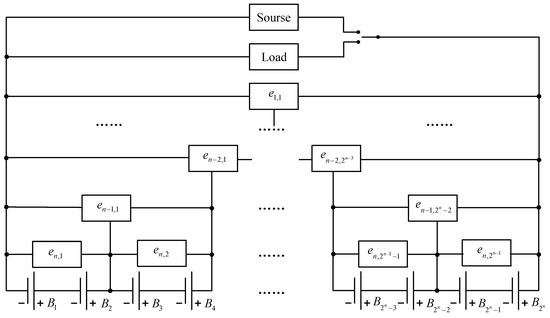
Figure 1.
Schematic diagram of equalization system composed of 2n single cells.
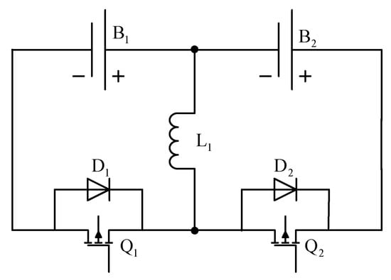
Figure 2.
Buck–Boost equalization circuit.
3.1. Equalizing Currents
In the m-th layer equalization circuit, the im equalizer can complete the bidirectional transfer of the current of its left and right adjacent battery modules ( and ), and the equalized current on the battery is and . As shown in Figure 2, to transfer energy from a high SOC battery to a low SOC battery it is necessary to control the equalization current through the equalizer to complete battery equalization. Before equalization, the current direction can be determined by the battery’s SOC, if the / is greater than the SOC of /, a new variable can be used to replace and .
where represents the equalization current flowing through the im equalizer on the m-th layer; k represents the magnitude and direction of the equilibrium current; represents the efficiency of the equalizer when transferring current; represents the total SOC of ; and represents the total SOC of , in Equation (1), 0 < < 1. To represent the current direction, when the SOC of is greater than the SOC of , the balanced current flowing through is less than 0, and the balanced current flowing through .
Combining the circuit shown in Figure 1 and the above analysis, in a battery module directly connected to the equalizer, the equalizing current values are equal, so the equalizing current flowing through each battery is:
where , , …, and is the equalization current of the upper equalizer of the m-section battery, 1 ≤ im ≤ 2m−1.
3.2. Battery Pack Equalization Model
For the ith battery in the battery pack, its SOC can be calculated by Equation (3):
where SOC is the ratio of the remaining power of the battery to the nominal capacity; , ,where Q represents the rated capacity of the battery; η represents the charge/discharge coulomb efficiency of the battery under different conditions; b is the time coefficient, which is numerically equal to the ratio of equilibrium current to maximum equilibrium current; T represents the sampling time; is the external current provided by the load or external power supply; is the equalization current flowing through the ith battery, which can be calculated by Equation (2); and Ii(k) represents the current flowing through the ith lithium battery. During the calculation process, the current is negative when discharging, and the current is positive when charging, which can be calculated; the SOC value of battery can be easily obtained by ampere-hour integration method. It can be seen from Equations (2) and (3) that the multi-layer equalization model of battery pack consisting of 2n batteries can be formulated in the following discrete state form:
where = [, , ,…, , , ]T represents the SOC of each battery in the battery pack; = [, , ,…, , , ]T denoting the equalization current flowing through each battery in the battery pack. Equation (5) only considers the current flowing through the battery without considering the complex chemical reaction inside the battery, which has stronger adaptability and is more conducive to practical use.
3.3. Cell Balancing Constraints
In order to ensure the safety of the equalization process and prevent overcharge, over-discharge and overheating of the battery, it is necessary to impose constraints on the equalization process. The constraints imposed in this study are current and SOC.
Equalizer current constraint: Excessive equalizing current causes serious heating of the equalizer and affects the service life of the equalizer. It is necessary to limit the equalizing current within a certain range. The current constraint can be expressed as:
where is the maximum value of equalization current.
Battery current constraint: Current has a significant impact on battery life and performance. Higher current will result in increased battery heating, which can result in major safety issues. As a result, the charge and discharge currents of the battery must be kept within a particular range to ensure the battery’s safe and reliable performance.
Although the exterior current of the battery pack remains constant during equalization, the current passing through each battery varies due to the equalization current’s influence. The discharge equalization current and charge equalization current will not occur at the same time since the equalizer works in BCM and DCM. To ensure that the working current of the battery is within the allowable range, the charge and discharge current of the battery is constrained respectively. The equalizing current flowing through the battery can be expressed by the following formula:
where and are the charge equalization current and discharge equalization current of battery i, respectively.
The maximum value of battery current is the sum of charge equalization current and external current, and the minimum value of battery current is the sum of discharge current and external current. The battery current can be expressed as:
The current constraint can be formulated by:
where represents the upper limit of charging and represents the upper limit of discharging current. To ensure the normal operation of the battery, the maximum charging and discharging current of the battery should be within the constraint range.
Battery SOC constraint: When the battery is overcharged and discharged, the performance and service life of the lithium battery will be affected to varying degrees, and even lead to safety accidents in serious cases. Therefore, the SOC of the battery must be constrained, the constraint relationship is as follows:
where and represent the upper and lower limits of battery SOC in the group, respectively.
This part builds a multi-layer equalization circuit model, analyzes the equalization current and battery current throughout the equalization process, and analyzes the external current, battery SOC and current, and equalization current limitations. According to Equations (6)–(9), the battery’s equalization current can change depending on the external current, limiting the battery’s maximum operating current. To shorten the equalization time, Equation (5) can obtain the optimal equalization current. The fluctuation of battery equilibrium current with internal resistance and SOC is only considered in Reference [36], and the maximum operating current of the battery was not taken into account. When the battery pack’s external current is too high, the current loaded on the battery is easily exceeded. The equilibrium method proposed in this study is safer and faster.
4. Multi-Layer Balancing Strategy
Based on the multi-layer equilibrium circuit model and constraints established in the previous section, this section mainly analyzes the equilibrium objectives and strategies.
4.1. Cell Balancing Task Formulation
The goal of equalization is to increase the battery pack’s consistency as well as the battery pack’s real capacity. The higher the equalization efficiency, the shorter the battery equalization time. The balancing goal can be formulated as:
where is the average value of SOC of all batteries, which can be expressed as:
where represents the SOC of the ith battery, the battery pack has 2n batteries in total, .
To improve the equilibrium efficiency, the objective function (11) can be minimized to design a control strategy that satisfies the constraints. The transformed function is:
subject to
The majority of balancing solutions simply evaluate the balancing control of adjacent cells, ignoring the battery pack’s influence from external current. Unlike the previous equalization technique, the equalization method proposed in this study considers all the battery current and equalization current constraints and optimizes the equalization current to maintain the battery current within safe limits. However, Equation (12) has a lot of variables, which puts a lot of strain on the processor and makes it difficult to apply in reality.
Considering the aforementioned flaws, this study presents a layered equalization technique that calculates the equalization current by treating the left and right battery modules attached to each equalizer as two separate batteries. After calculating the upper circuit’s equalizing current, it is used as an input to calculate the below equalizing current, layer by layer, until the total equalizing current of all equalizing units is obtained. The equalizing current calculation formula is similar to Equation (1). The layered equalization strategy will be introduced in detail below.
4.2. Equilibrium Strategy Analysis
Under the above equalization circuit, each battery in battery module has the same equalization current. Battery module can be regarded as a single battery, and only single battery equalization can be considered.
The m-layer equilibrium model can be regarded as:
where is the average SOC of the battery module on the left side of an equalizer on layer m; and represents the equalization current of layer m.
According to Equations (13) and (14), the following optimization model can be obtained:
subject to
where represents the maximum charging current flowing through battery modules and ; represents the maximum discharge current flowing through battery modules and ; and represents the equalization current of layer m.
Using the PS0 to solve the above model, the optimal equilibrium current of the m-layer can be calculated.
It can be seen from the above analysis that n2n dimensional matrix must be solved before layering; the m-th layer should be solved for m times after layering, and the entire module should be solved for 2n − 1 times. After stratification, the calculating difficulty is lessened, making it more practical to use.
5. Simulation Results
The simulation experiments were carried out on MATLAB, which used three levels of equalization circuits and eight batteries to validate the performance of the aforesaid layered equalization technique. The battery’s nominal capacity was set to 0.2 ah to speed up the simulation. The battery’s SOC allowed range was 0–100% during the simulation, and the equalizer’s maximum equalization current and efficiency were 1 A and 80%, respectively; and the battery current allowable range was (−3 A, 3 A). Figure 3 illustrates the battery pack’s external current. Equalization is defined as the least square sum of the battery pack’s SOC and its average SOC being less than 0.01, and the equalization time is defined as the time from start to end of equalization. The specific simulation parameters are shown in Table 3 and Table 4.
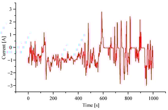
Figure 3.
External current for the battery pack.
Table 3.
Simulation battery parameters.
Table 4.
Other components.
5.1. Battery Pack Equalization Results
First, the initial SOC of the battery in the group was randomly selected. As shown in Figure 4, the least square sum of the battery pack’s SOC and its average SOC is 0.06.
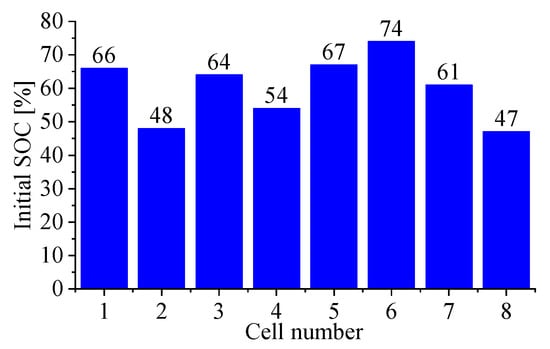
Figure 4.
Initial SOC.
Scholars have proposed a variety of multi-layer circuit equalization strategies. To improve the equalization efficiency, the multi-layer equalization circuit works at the same time, which leads to excessive battery current and increased battery heat production under certain circumstances. After simulation analysis, the difference between the SOC, current, SOC and the average value of the battery’s SOC is shown in Figure 5, Figure 6 and Figure 7. The simulation results show that when the equalization time is 245.7 s, the SOC of the battery pack reaches equilibrium. When working under large external current, the battery charge and discharge current exceeds the allowable value.
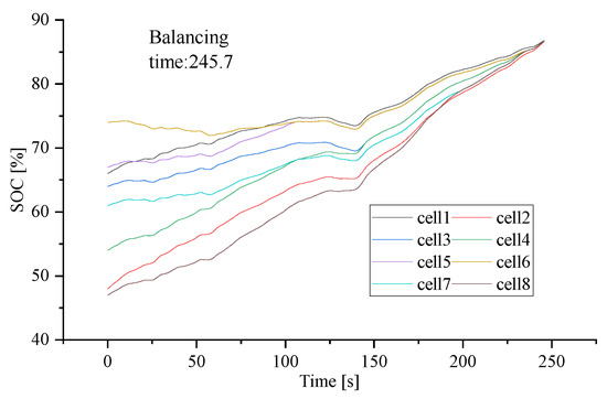
Figure 5.
Lithium battery SOC change chart. (Multi-layer equalisation circuit without equalisation strategy).
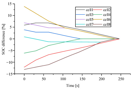
Figure 6.
Lithium battery SOC difference diagram. (Multi-layer equalisation circuit without equalisation strategy).
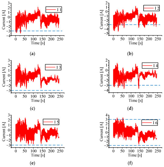
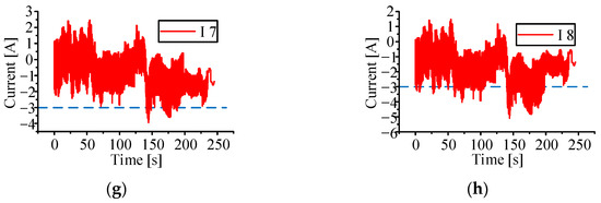
Figure 7.
(a–h) lithium battery current change diagram, the blue dotted line represents the normal operating current range. (Multi-layer equalisation circuit without equalisation strategy).
The simulation calculation process of the equilibrium strategy proposed in this study is as follows:
- (1)
- Firstly, collect the SOC and current values of the batteries in the group, calculate the average values of batteries 1–4 and 5–8, determine the size and direction of the equilibrium current;
- (2)
- The objective function of equalization current can be obtained from Equation (15), and the best equalization current of the first layer can be obtained by PSO;
- (3)
- Calculate the average SOC of batteries 1–2, 3–4, 5–6, and 7–8, determine the size and flow direction of the equalization current, and bring into Equation (14). The objective function is calculated from Equation (15); calculate the best equalization current of the second layer through PSO;
- (4)
- Collect the SOC value of batteries 1–8, determine the size and flow direction of equalization current, bring into Equation (14), calculate the objective function from Equation (15), and calculate the best equalization current of the third layer through PSO;
- (5)
- Repeat the above four steps until the battery pack is balanced.
Figure 8, Figure 9 and Figure 10 demonstrate the difference between the battery’s SOC, current, SOC, and the average value of SOC after the aforesaid calculation and simulation method. The simulation results show that when the equalization time reaches 268.05 s, the equalization is achieved. The battery charge and discharge currents do not exceed the permitted value when the battery pack is working under high external current, showing that the proposed multi-layer equalization technique performs better. Figure 11 shows the equalizing current, which changes based on changes in external loading current, effectively preventing the battery from overheating and ensuring that the battery operates normally at all times.
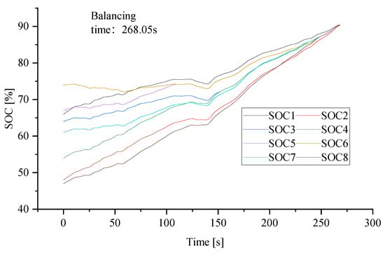
Figure 8.
Lithium battery SOC change chart. (Multi-layer equalisation circuits and equalisation strategies in this paper).
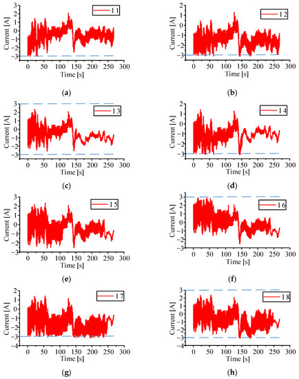
Figure 9.
(a–h) lithium battery current change diagram, the blue dotted line represents the normal operating current range. (Multi-layer equalisation circuits and equalisation strategies in this paper).
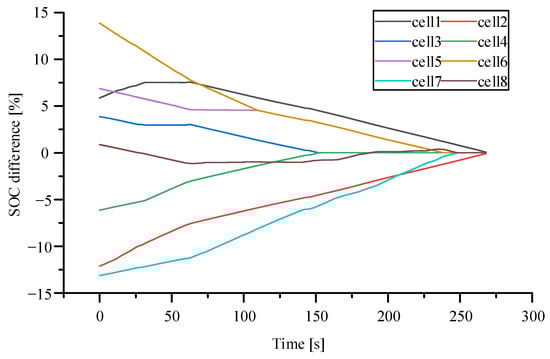
Figure 10.
Lithium battery SOC difference diagram. (Multi-layer equalisation circuits and equalisation strategies in this paper).
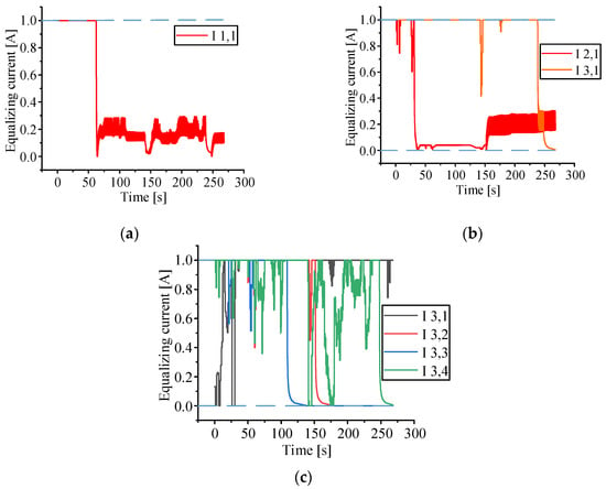
Figure 11.
(a) the first layer equalization current, (b) the second layer equalizes the current, (c) the third layer equalizes the current, the blue dotted line represents the equalization current range.
5.2. Comparison with Adjacent Equilibrium
A simulation analysis of the generally used adjacent cell equalization methods was also carried out to prove the performance of the multi-layer equalization strategy presented in this study. Figure 12 shows the circuit arrangement utilized to balance adjacent cells. The SOC of the two neighboring cells determines the current direction of each equalizer, and the size is always 1 A. The current variation in battery 2 is shown in Figure 13, with a maximum current of 4.83 A. Some battery cells in the battery pack have a charge and discharge current that is more than the permitted current, resulting in negative consequences such as increased heat generation and reduced performance in some circumstances. Figure 14 shows each battery SOC change, and the equalization time is 350.65 s. According to the equalization results, the proposed multi-layer equalization strategy’s equilibrium efficiency is raised by 23.55% compared with the adjacent battery equalization approach, demonstrating the proposed multi-layer equalization strategy’s good performance.
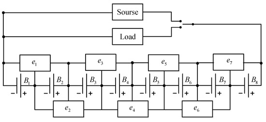
Figure 12.
The adjacent cell balancing circuit.
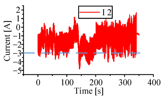
Figure 13.
Lithium battery current change diagram, the blue dotted line represents the normal operating current range. (Adjacent equalisation circuits without equalisation strategy).
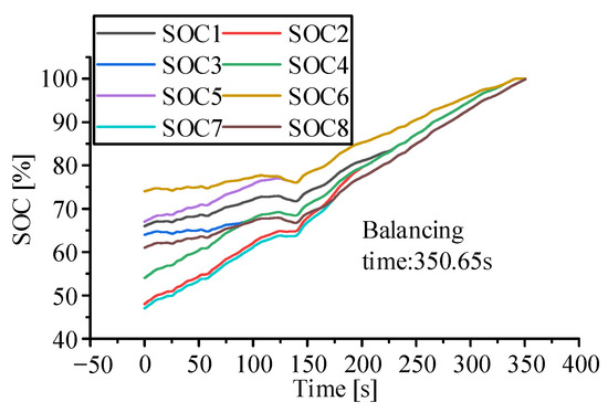
Figure 14.
Lithium battery SOC change chart. (Adjacent equalisation circuits without equalisation strategy).
5.3. Comparison of Fuzzy Control Method with Adjacent Equalization Circuit
The fuzzy control mechanism was also simulated and examined in this study. Figure 15 shows the current flowing via the battery 2. Despite the reduced maximum current, the battery current still exceeds the limit. Figure 16 shows that when a battery is completely charged, the batteries in the group do not reach equalization due to the reduced equalization current.
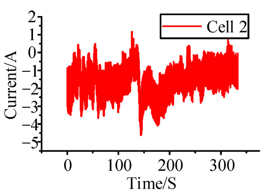
Figure 15.
Lithium battery current change diagram. (Adjacent equalisation circuits and fuzzy control strategies).
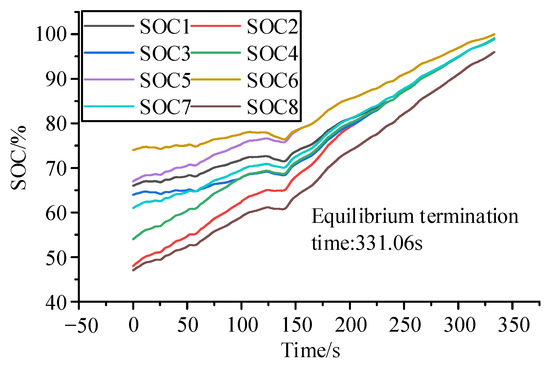
Figure 16.
Lithium battery SOC change chart. (Adjacent equalisation circuits and fuzzy control strategies).
5.4. Comparison with the Control Method Based on SOC Difference
The control approach based on SOC difference was also simulated and examined in this article. Figure 17 shows the current flowing via the battery 2. Although the maximum current was reduced, the battery current will continue to exceed the limit. Figure 18 shows that when a battery is fully charged, the group of batteries does not approach equilibrium.
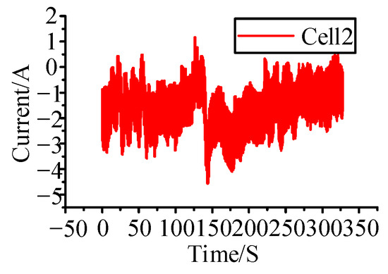
Figure 17.
Lithium battery current change diagram. (Adjacent equalisation circuits and SOC difference-based equalisation strategies).
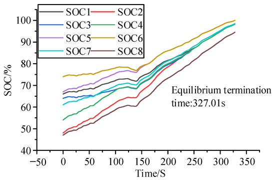
Figure 18.
Lithium battery SOC change chart. (Adjacent equalisation circuits and SOC difference-based equalisation strategies).
5.5. Different Initial SOC Equalization Test
To demonstrate the adaptability of the proposed multi-layer balancing strategy, the following four sets of tests were performed under the external current used above, and the initial SOC of the four sets of batteries is shown below:
- Case 1: SOC(0) = [66, 48, 64, 54, 67, 74, 61, 47];
- Case 2: SOC(0) = [53, 28, 25, 55, 32, 41, 37, 48];
- Case 3: SOC(0) = [25, 29, 32, 36, 42, 47, 52, 55];
- Case 4: SOC(0) = [27, 40, 47, 25, 36, 52, 55, 32].
Figure 19 shows the simulation results after they were balanced. The simulation results demonstrate that the proposed multi-layer balancing strategy is capable of achieving battery balancing within the group under a variety of initial SOC values, and that its performance outperforms neighboring battery balancing.
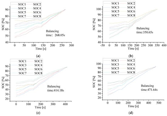
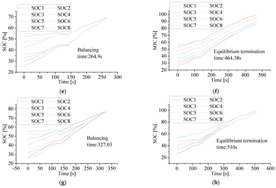
Figure 19.
(a) case l multi-layer equilibrium, (b) case 1 adjacent equilibrium, (c) case 2 multi-layer equilibrium, (d) case 2 adjacent equilibrium, (e) case 3 multi-layer equilibrium, (f) case 3 adjacent equilibrium, (g) case 4 multi-layer equilibrium, (h) case 4 adjacent equilibrium.
5.6. Overall Analysis
The performance of the equalization method tested is shown in Table 5. When the multi-layer equalization circuit does not use the equalization method, the equalization time is 245.7 s and the maximum battery current is 5.04 A, which is significantly more than the 3 A allowed by this study. The proposed equalization method has a time of equalization of 268.5 s and a maximum current of 3 A, which is within the allowable range. The equalization time is 350.65 s and the maximum current is 4.93 A when the adjacent battery equalization circuit is used and the equalization strategy is not applied, surpassing the maximum permitted current. The battery pack did not reach equalization using the fuzzy control equalization approach, and the highest equalization current was 4.72 A. Despite the fact that the current was lowering, it was still above the limit. The battery pack did not attain equilibrium using the control approach based on SOC difference, and the maximum equilibrium current was 4.68 A, surpassing the maximum permitted current. To summarize, the proposed layered control method based on multi-layer equalization circuit can take use of the multi-layer equalization circuit’s high equalization speed while keeping the battery current within the permissible range, which ensures both the equalization speed and the safety of the equalization process.
Table 5.
Comparison of equilibrium results.
6. Conclusions
In this study, the balance problem of series lithium battery pack is optimized, a mathematical model of multi-layer balance circuit is established. In order to achieve a safe and fast balance of the battery pack a multi-objective optimization problem is proposed, which takes into account the balancing time, external current, and battery current to optimize the balancing current, maintain the battery current within the allowable range, and reduces battery heating. To improve the computational efficiency and reduce the computational difficulty, a new proposed layered equalization strategy was used to calculate the equalization current of the battery pack in layers, which can realize the fast calculation of the equalization current. Through theoretical analysis and simulation results, the balance strategy proposed in this study was found to be safer than the multi-layer balance circuit without the balance strategy, and the battery current is kept within the allowable range during the balancing process; the balancing efficiency is 23.55% higher than that of adjacent cells. It was proven that the balancing strategy proposed in this study can quickly and safely achieve the balance of the battery pack.
Author Contributions
Conceptualization, L.W., X.L. (Xu Lu) and C.C.; methodology, X.L. (Xu Lu) and H.L.; software, X.L. (Xu Lu), J.S. and X.L. (Xiangyang Li); validation, X.L. (Xu Lu), H.L., X.L. (Xiangyang Li) and L.W.; formal analysis, X.L. (Xu Lu); investigation, X.L. (Xu Lu) and H.L.; resources, X.L. (Xu Lu) and X.L. (Xiangyang Li); data curation, X.L. (Xu Lu); writing—original draft preparation, X.L. (Xu Lu); writing—review and editing, X.L. (Xu Lu); visualization, H.L.; supervision, L.W. and C.C.; project administration, L.W. and C.C.; funding acquisition, L.W., X.L. (Xu Lu) and C.C. All authors have read and agreed to the published version of the manuscript.
Funding
This research was supported by the National Natural Science Foundation of China Youth Fund, grant number 62003315; ZHONGYUAN Talent Program, grant number ZYYCYU202012112; the Applied Basic Research Program of Shanxi Province, grant number 201901D211241; Scientific and Technological Project of Henan Province, grant number 212102210069; 222102210043; and The Young Academic Leaders Support Program of the North University of China, grant number QX202002. Henan International Joint Laboratory of Thermo-Fluid Electro-Chemical System for New Energy Vehicle, grant number Yuke2020-23. Fund of Innovative Education Program for Graduate Students at North China University of Water Resources and Electric Power, China, grading number YK-2021-91.
Institutional Review Board Statement
Not applicable.
Informed Consent Statement
Not applicable.
Data Availability Statement
Data are contained within the article.
Conflicts of Interest
The authors declare no conflict of interest.
References
- El-Batawy, S.A.; Morsi, W.G. Optimal Design of Community Battery Energy Storage Systems With Prosumers Owning Electric Vehicles. IEEE Trans. Ind. Inform. 2018, 14, 1920–1931. [Google Scholar] [CrossRef]
- Zhang, Q.; Deng, W.; Li, G. Stochastic control of predictive power management for battery/supercapacitor hybrid energy storage systems of electric vehicles. IEEE Trans. Ind. Inform. 2017, 14, 3023–3030. [Google Scholar] [CrossRef]
- Wang, H.; Huang, Y.J.; Khajepour, A. Cyber-Physical Control for Energy Management of Off-Road Vehicles With Hybrid Energy Storage Systems. IEEE-ASME Trans. Mechatron. 2018, 23, 2609–2618. [Google Scholar] [CrossRef]
- Zhang, Y.Z.; Xiong, R.; He, H.W.; Pecht, M. Validation and verification of a hybrid method for remaining useful life prediction of lithium-ion batteries. J. Clean. Prod. 2019, 212, 240–249. [Google Scholar] [CrossRef]
- Zheng, L.F.; Zhu, J.G.; Wang, G.X.; Lu, D.D.C.; He, T.T. Lithium-ion Battery Instantaneous Available Power Prediction Using Surface Lithium Concentration of Solid Particles in a Simplified Electrochemical Model. IEEE Trans. Power Electron. 2018, 33, 9551–9560. [Google Scholar] [CrossRef]
- Yuan, M.X.; Chen, Z.; Yao, B.; Liu, X.Y. Fast and Accurate Motion Tracking of a Linear Motor System Under Kinematic and Dynamic Constraints: An Integrated Planning and Control Approach. IEEE Trans. Control Syst. Technol. 2021, 29, 804–811. [Google Scholar] [CrossRef]
- Yuan, M.X.; Chen, Z.; Yao, B.; Hu, J.F. A General Online Trajectory Planning Framework in the Case of Desired Function Unknown in Advance. IEEE Trans. Ind. Inform. 2019, 15, 2753–2762. [Google Scholar] [CrossRef]
- Xu, B.L.; Oudalov, A.; Ulbig, A.; Andersson, G.; Kirschen, D.S. Modeling of Lithium-Ion Battery Degradation for Cell Life Assessment. IEEE Trans. Smart Grid 2018, 9, 1131–1140. [Google Scholar] [CrossRef]
- Yang, J.F.; Xia, B.; Huang, W.X.; Fu, Y.H.; Mi, C. Online state-of-health estimation for lithium-ion batteries using constant-voltage charging current analysis. Appl. Energy 2018, 212, 1589–1600. [Google Scholar] [CrossRef]
- Wang, D.; Yang, F.F.; Tsui, K.L.; Zhou, Q.; Bae, S.J. Remaining Useful Life Prediction of Lithium-Ion Batteries Based on Spherical Cubature Particle Filter. IEEE Trans. Instrum. Meas. 2016, 65, 1282–1291. [Google Scholar] [CrossRef]
- Abdullah-Al, M.; Liu, Z.F.; Rizzo, D.M.; Onori, S. An Integrated Design and Control Optimization Framework for Hybrid Military Vehicle Using Lithium-Ion Battery and Supercapacitor as Energy Storage Devices. IEEE Trans. Transp. Electrif. 2019, 5, 239–251. [Google Scholar]
- Ouyang, Q.; Chen, J.; Zheng, J.; Fang, H.Z. Optimal Multiobjective Charging for Lithium-Ion Battery Packs: A Hierarchical Control Approach. IEEE Trans. Ind. Inform. 2018, 14, 4243–4253. [Google Scholar] [CrossRef]
- Ouyang, D.X.; Liu, J.H.; Chen, M.Y.; Wang, J. Investigation into the Fire Hazards of Lithium-Ion Batteries under Overcharging. Appl. Sci. 2017, 7, 1314. [Google Scholar] [CrossRef] [Green Version]
- Hoekstra, F.S.J.; Bergveld, H.J.; Donkers, M.C.F. Optimal Control of Active Cell Balancing: Extending the Range and Useful Lifetime of a Battery Pack. In IEEE Transactions on Control Systems Technology; IEEE: Piscataway, NJ, USA, 2022. [Google Scholar]
- Zhang, S.Z.; Peng, N.; Lu, H.B.; Li, R.; Zhang, X.W. A systematic and low-complexity multi-state estimation framework for series-connected lithium-ion battery pack under passive balance control. J. Energy Storage 2022, 48, 104321. [Google Scholar] [CrossRef]
- Tang, X.P.; Gao, F.R.; Liu, K.L.; Liu, Q.; Foley, A.M. A Balancing Current Ratio Based State-of-Health Estimation Solution for Lithium-Ion Battery Pack. IEEE Trans. Ind. Electron. 2022, 69, 8055–8065. [Google Scholar] [CrossRef]
- Xu, J.; Mei, X.S.; Wang, H.T.; Shi, H.; Sun, Z.; Zou, Z.Y. A model based balancing system for battery energy storage systems. J. Energy Storage 2022, 49, 104114. [Google Scholar] [CrossRef]
- Wu, S.T.; Chang, Y.N.; Chang, C.Y.; Cheng, Y.T. A Fast Charging Balancing Circuit for LiFePO4 Battery. Electronics 2019, 8, 1144. [Google Scholar] [CrossRef] [Green Version]
- Pham, V.L.; Duong, V.T.; Choi, W. A Low Cost and Fast Cell-to-Cell Balancing Circuit for Lithium-Ion Battery Strings. Electronics 2020, 9, 248. [Google Scholar] [CrossRef] [Green Version]
- Feizi, M.; Beiranvand, R. A high-power high-frequency self-balanced battery charger for lithium-ion batteries energy storage systems. J. Energy Storage 2021, 41, 102886. [Google Scholar] [CrossRef]
- Moghaddam, A.F.; Van den Bossche, A. An Efficient Equalizing Method for Lithium-Ion Batteries Based on Coupled Inductor Balancing. Electronics 2019, 8, 136. [Google Scholar] [CrossRef] [Green Version]
- Chen, F.; Yuan, J.; Zheng, C.; Wang, C.; Li, Z.; Zhou, X. A State-of-Charge Based Active EV Battery Balancing Method. In Proceedings of the 2018 2nd International Conference on Electrical Engineering and Automation (ICEEA 2018), Chengdu, China, 25–26 March 2018. [Google Scholar]
- Cao, J.W.; Xia, B.Z.; Zhou, J. An Active Equalization Method for Lithium-ion Batteries Based on Flyback Transformer and Variable Step Size Generalized Predictive Control. Energies 2021, 14, 207. [Google Scholar] [CrossRef]
- Moghaddam, A.F.; Van den Bossche, A. A Cuk Converter Cell Balancing Technique by Using Coupled Inductors for Lithium-Based Batteries. Energies 2019, 12, 2881. [Google Scholar] [CrossRef] [Green Version]
- Shang, Y.L.; Xia, B.; Lu, F.; Zhang, C.H.; Cui, N.X.; Mi, C.T.C. A Switched-Coupling-Capacitor Equalizer for Series-Connected Battery Strings. IEEE Trans. Power Electron. 2017, 32, 7694–7706. [Google Scholar] [CrossRef]
- Ye, Y.M.; Cheng, K.W.E.; Fong, Y.C.; Xue, X.D.; Lin, J. Topology, Modeling, and Design of Switched-Capacitor-Based Cell Balancing Systems and Their Balancing Exploration. IEEE Trans. Power Electron. 2017, 32, 4444–4454. [Google Scholar] [CrossRef]
- Shang, Y.L.; Zhang, Q.; Cui, N.X.; Duan, B.; Zhang, C.H. A Optimized Mesh-Structured Switched-Capacitor Equalizer for Lithium-Ion Battery Strings. IEEE Trans. Transp. Electrif. 2019, 5, 252–261. [Google Scholar] [CrossRef]
- Zhang, Y.L.; Hong, Y.; Choi, K. Optimal energy-dissipation control for SOC based balancing in series connected Lithium-ion battery packs. Multimed. Tools Appl. 2020, 79, 15923–15944. [Google Scholar] [CrossRef]
- Wu, X.G.; Cui, Z.H.; Li, X.F.; Du, J.Y.; Liu, Y. Control Strategy for Active Hierarchical Equalization Circuits of Series Battery Packs. Energies 2019, 12, 2071. [Google Scholar] [CrossRef] [Green Version]
- Chen, Y.; Shen, T.; Yang, S.Y.; Liu, X.F.; Yang, R.; Cheng, L.F. A Path Planning Strategy with Ant Colony Algorithm for Series Connected Batteries. Electronics 2020, 9, 1816. [Google Scholar] [CrossRef]
- Zhang, Z.Y.; Zhang, L.Z.; Hu, L.; Huang, C.X. Active cell balancing of lithium-ion battery pack based on average state of charge. Int. J. Energy Res. 2020, 44, 2535–2548. [Google Scholar] [CrossRef]
- Lv, J.; Song, W.J.; Lin, S.L.; Chen, M.B.; Feng, Z.P.; Li, Y.L.; Ding, Y.L. Influence of equalization on LiFePO4 battery inconsistency. Int. J. Energy Res. 2017, 41, 1171–1181. [Google Scholar] [CrossRef]
- Sun, W.B.; Li, Y.L.; Liu, L.Z.; Mai, R.K. A switched-capacitor battery equalization method for improving balancing speed. IET Electr. Power Appl. 2021, 15, 555–569. [Google Scholar] [CrossRef]
- Wang, Y.X.; Zhong, H.; Li, J.W.; Zhang, W. Adaptive estimation-based hierarchical model predictive control methodology for battery active equalization topologies: Part I-Balancing strategy. J. Energy Storage 2022, 45, 103235. [Google Scholar] [CrossRef]
- Liao, L.; Chen, H. Research on two-stage equalization strategy based on fuzzy logic control for lithium-ion battery packs. J. Energy Storage 2022, 50, 104321. [Google Scholar] [CrossRef]
- Zhang, L.C. Research on a balanced circuit and control strategy. Int. J. Low-Carbon Technol. 2020, 15, 607–612. [Google Scholar] [CrossRef]
- Zheng, L.; Zhu, J.; Wang, G.; Lu, D.D.-C.; McLean, P.; He, T. Model predictive control based balancing strategy for series-connected lithium-ion battery packs. In Proceedings of the 2017 19th European Conference on Power Electronics and Applications (EPE’17 ECCE Europe), Warsaw, Poland, 11–14 September 2017. [Google Scholar]
Publisher’s Note: MDPI stays neutral with regard to jurisdictional claims in published maps and institutional affiliations. |
© 2022 by the authors. Licensee MDPI, Basel, Switzerland. This article is an open access article distributed under the terms and conditions of the Creative Commons Attribution (CC BY) license (https://creativecommons.org/licenses/by/4.0/).