Article

Analytical Approximations for Sub Wavelength Sound Absorption by Porous Layers with Labyrinthine Slit Perforations

by
Keith Attenborough
Engineering and Innovation, The Open University, Milton Keynes MK7 6AA, UK
Appl. Sci. 2021, 11(8), 3299; https://doi.org/10.3390/app11083299
Submission received: 19 March 2021 / Revised: 2 April 2021 / Accepted: 6 April 2021 / Published: 7 April 2021
(This article belongs to the Special Issue Vibration and Sound Control by Acoustic Meta Structures)

Abstract

:
Analytical approximations for the acoustical properties of a rigid-porous matrix perforated by labyrinthine slits are developed using classical theories for sound propagation in tortuous slits and for sound absorption by double porosity materials. Predictions of enhanced low-frequency absorption result from a combination of pressure diffusion and labyrinth tortuosity if there is a high permeability contrast between the matrix and the labyrinthine slit. Additional insight into the predicted influence of the properties of the porous matrix is gained by considering the matrix porosity to be provided by inclined micro-slits. Extra tortuosity can be introduced by alternating the width of the labyrinthine slit. An alternating-width vertical-wall labyrinth perforation is predicted to lead to low-frequency absorption peaks in a relatively low-flow-resistivity and low-porosity matrix. Example predictions, even when using underestimates of labyrinth tortuosity, demonstrate the potential of labyrinthine slit perforations for achieving narrowband deep sub wavelength absorption peaks from thin hard-backed porous layers.

1. Introduction

Conventional ways of improving the low-frequency absorption by a porous layer are to increase its thickness and to mount it with an air space between it and a rigid backing surface. Restrictions on space and weight in aerospace or automotive applications make such solutions impractical. Perforation of porous materials may improve their sound absorption [1,2]. Long convoluted sound channels or labyrinths in a solid matrix result in good impedance matching [3] and high absorption coefficients at wavelengths much greater than the layer thickness [4]. However, computations for complex perforations and for labyrinthine structures use numerical methods such as Finite Element Modelling. This paper offers analytical approximations for predicting the result of making labyrinthine slit perforations in a rigid-porous layer. An array of narrow labyrinthine slits in a non-porous solid may be considered as if it were a porous material with highly tortuous slit pores. In this paper, contiguous units, each of which contains a labyrinthine slit, are considered to form a rigid-porous solid acting, acoustically, as an effective fluid layer. Analytical approximations for the acoustical properties of horizontal- and vertical-wall labyrinths in a non-porous matrix use the classical result for sound propagation in a rigid-porous medium with tortuous slit-like pores [5]. Then the dual-porosity theory [6,7] is used to predict the results of incorporating labyrinthine slits in a matrix of a rigid-porous material with high flow resistivity. The influence of additional tortuosity due to changes in labyrinthine slit cross section [8] is considered. Useful narrowband low-frequency absorption is predicted to result from pressure diffusion and tortuosity effects. Example predictions suggest that labyrinthine slit perforations in porous materials offer a great potential for deep sub wavelength narrowband absorption peaks.

2. Labyrinthine Slits Formed by Walls Parallel and Normal to the Layer Surface

Consider a plane wave at normal incidence on a layer of contiguous rectangular unit cells, each of which contains a single labyrinthine slit of width b with N folds in the slit formed by walls of length l and width w. The walls are either parallel to (
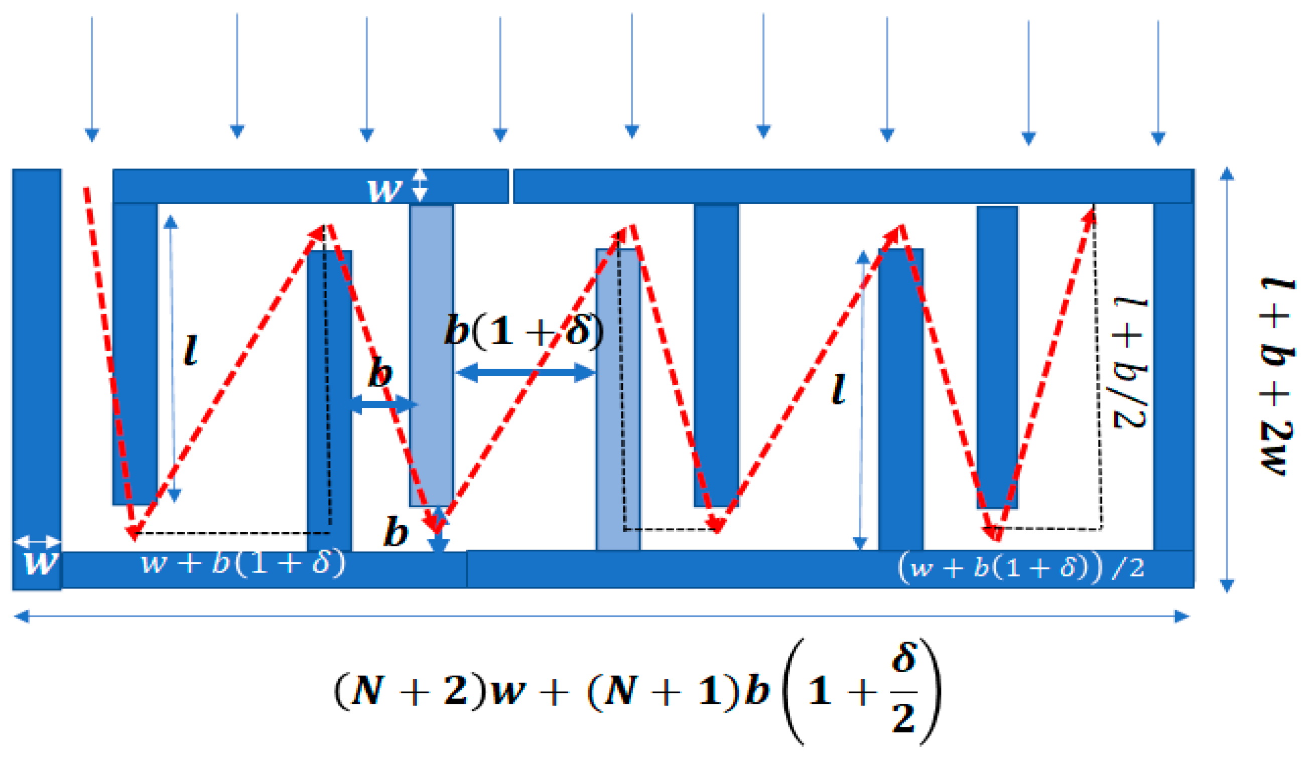
Figure 1a) or normal to (Figure 1b) the surface on which the wave is incident. In this paper, the former arrangement is called a horizontal-wall labyrinth and the latter arrangement is called a vertical-wall labyrinth. Associated parameters are given H or V subscripts.
The shortest paths through the slit labyrinths are approximated by the zigzag paths represented by broken lines in Figure 1a,b. The corresponding tortuosity values ( T H Z , T V Z ) are underestimates since the fluid streamlines must pass around the internal walls. On the other hand, calculations of tortuosity ( T H C ,   T V C ) using piecewise linear paths along the centres of the labyrinthine slits are overestimates since the streamlines will curve around corners. Expressions for labyrinth tortuosity corresponding to Figure 1a,b and according to these streamline path length estimates are given in Equations (1) to (4), respectively. Predictions in this paper assume the zigzag path approximations.
T H Z = { ( N 1 ) ( l + b ) 2 + ( b + w ) 2 + ( l + b / 2 ) 2 + ( b + w ) 2 / 4 + w / 2 [ ( N + 1 ) w + N b ] ( N + 1 ) w + N b } 2 ,
T H C = [ N l w b / 2 ( N + 1 ) w + N b ] 2
T V Z = { ( N 1 ) l 2 + ( b + w ) 2 + l 2 + ( b + w ) 2 / 4 + ( l + b / 2 ) 2 + ( b + w ) 2 / 4 w b / 2 l l + b + 2 w } 2 ,
T V C = [ N ( l + b ) + ( N 1 ) w l + b + 2 w ] 2
The expressions for bulk, Ω B , and surface, Ω S , porosities of the horizontal- and vertical-wall labyrinth structures in Figure 1 are given in Equations (5) to (8),
Ω B H = { [ N b ( l + b + w ) ] / [ ( ( N + 1 ) w + N b ) ( l + b + 2 w ) ] } ,  
Ω S H = b / ( l + b + 2 w )
Ω B V = { [ ( N + 1 ) ( l + b + w ) b ] / [ ( ( N + 2 ) w + ( N + 1 ) b ) ( l + b + 2 w ) ] } ,
Ω S V = b / ( ( N + 2 ) w + ( N + 1 ) b )
The complex density, ( ρ L ( ω ) ), complex compressibility, ( C L ( ω ) ), propagation constant, ( k L ( ω ) ), and normalised impedance ( Z L ( ω ) ) of an effective fluid medium equivalent to a labyrinthine slit structure are, respectively [5],
ρ L ( ω ) = ( T / Ω B ) ρ ( ω ) ,   ρ ( ω ) = ρ 0 / H ( λ ) ,   H ( λ ) = 1 tanh ( λ i ) / ( λ i ) ,   C L ( ω ) = Ω B C ( ω )
C ( ω )   =   ( ρ 0 c 0 2 ) 1 [ γ     ( γ     1 ) H ( λ ( N PR ) ) ] ,   λ = ( b / 2 ) ω ρ 0 / μ ,   k L ( ω ) = ω ρ L ( ω ) C L ( ω ) ,   Z L ( ω ) = ( Ω S ρ 0 c 0 ) 1 ρ L ( ω ) / C L ( ω )
ρ 0 ,   c 0 ,   N P R   and   μ are density, sound speed, Prandtl number and dynamic viscosity in air, respectively, Ω B is either Ω B H or Ω B V , Ω S is either Ω S H or Ω S V and T is either T H Z or T V Z . Time dependence e i ω t is understood where i = ( 1 ) .

3. Labyrinthine Slit Perforations in a Rigid-Porous Matrix

With sufficient scale separation between the characteristic matrix pore size and the labyrinthine slit width, a labyrinthine perforation in a porous matrix may be regarded as a dual-porosity system. If there is a high permeability contrast between the matrix and the labyrinth, the resulting bulk complex density, ρ d p L , and complex compressibility, C d p L , are [6],
ρ d p L ( ω ) = [ 1 ρ L ( ω ) + ( 1 Ω B ) ρ m ( ω ) ] 1 ,   C d p L ( ω ) = C L ( ω ) + ( 1 Ω B ) F d ( ω ) C m ( ω ) ,
where ρ m and C m represent the complex density and compressibility of the rigid-porous matrix and F d ( ω ) is the pressure diffusion function.
For a high permeability contrast, F d ( ω ) , is given by [6,7]
F d ( ω ) = [ 1 + i ω ω d D ( ω ) D ( 0 ) ] ,   D ( ω ) = D ( 0 ) i ω ω d + 1 i M ( ω ) 2 ω ω d ,   D ( 0 ) = ( 1 Ω B ) ( ( L / 2 ) 2 3 )
M ( ω ) = 8 D ( 0 ) Λ d 2 ( 1 Ω m ) ,   Λ d = 2 ( l + w ) ( ( N + 1 ) w + N b ) ( N + 2 ) w + N b + l ,   ω d = ( 1 Ω B ) P 0 Ω m σ m D ( 0 )
where D ( ω ) is a dynamic pressure permeability function, D ( 0 ) is the static pressure permeability involving half the width, L , between perforation openings at the surface and Λ d is a pressure diffusion length. Ω m and σ m denote the porosity and flow resistivity of the porous matrix, respectively. In a horizontal-wall labyrinth, the distance between adjacent slit openings, L , is ( l + w ) . In a vertical-wall labyrinth, the distance between adjacent slit openings is [ ( N + 1 ) w + N b ] .
In Figure 2a, | F d ( ω ) | is plotted as a function of frequency for a 10-fold vertical-wall labyrinthine slit perforation, in which a 3 mm wide labyrinthine slit is formed by 1 mm wide, 45 mm long walls, in a porous matrix in which the pores have the form of micro-slits (0.04 mm wide slits inclined at 70° to the normal, porosity 0.9). The acoustical properties of a matrix of parallel identical slits of width b s inclined at θ to the normal are given by Equations (9) and (10) with Ω B replaced by Ω m , b replaced by b s and T = T m = 1 / ( c o s ( θ ) ) 2 [5].
The flow resistivity, σ , due to slit-like pores is calculated from [5]
σ = 12 μ T Ω b 2
where T ,   Ω ,   b are appropriate for the labyrinthine slit or inclined slit matrix.
The flow resistivity of the labyrinthine slit in a non-porous matrix (3.5 kPa s m−2) is much smaller than that (1297 kPa s m−2) of the porous matrix. Figure 2b shows the corresponding prediction for the imaginary part of the bulk modulus, K d p L ( ω ) = 1 / C d p L ( ω ) , which shows a peak near the pressure diffusion frequency (97.5 Hz).
Figure 3 shows predictions of normal incidence absorption spectra assuming 5.8 cm thick hard-backed layers of rockwool or melamine foam with parameters according to the Johnson–Champoux–Allard–Lafarge (JCAL) model (see Table 1) with and without horizontal-wall labyrinthine slit perforations. The frequency range plotted in the figures is restricted to below 1 kHz since the low-frequency performance is of most interest. As with other forms of perforation [1,2], the higher permeability contrast between the perforation and the porous matrix yields the more significant change in low-frequency absorption.
Figure 4a,b show predictions of normal incidence absorption coefficient spectra for a 5 cm thick hard-backed very-high-flow-resistivity slanted slit matrix with (solid line) and without (dotted line) horizontal- and vertical-wall labyrinthine slit perforations, respectively.
The absorption peaks at 240 Hz in Figure 4a and 170 Hz in Figure 4b correspond to the layer thickness being 1/28th and 1/40th of the incident wavelength, respectively. Also shown are absorption spectra predicted for the labyrinthine slit perforations in a non-porous rigid solid structure (broken black lines in Figure 4a,b) which result in rather narrow absorption peaks.
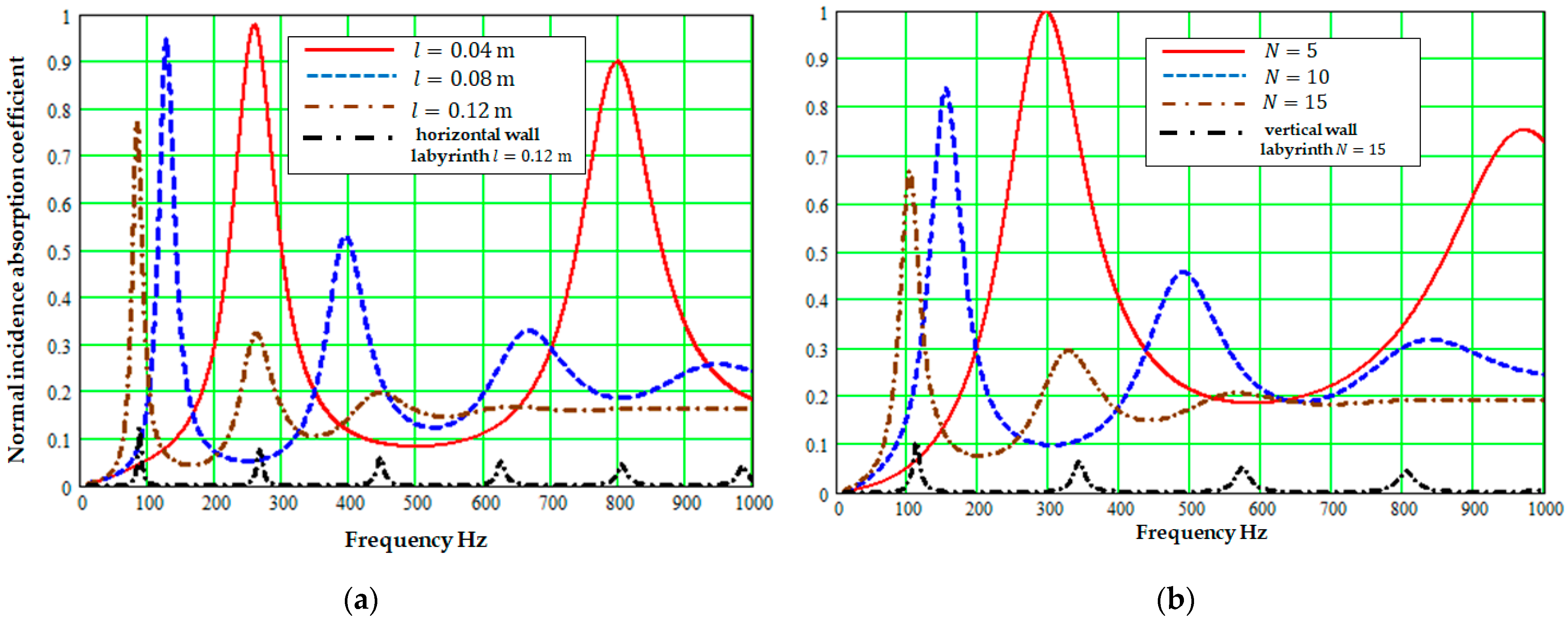
For a horizontal-wall configuration such as that shown in Figure 1a, if the wall width, labyrinthine slit width and slit folding number and hence the corresponding layer thickness, ( N + 1 ) w + N b , are fixed, then the tortuosity and hence the frequency of the lowest-frequency absorption peak are determined by the wall length. In a vertical-wall configuration such as that shown in Figure 1b, if the wall width, wall length, and labyrinthine slit width and hence the layer thickness, l + b + 2 w , are fixed, then the tortuosity and hence the frequency of the lowest-frequency absorption peak are dominated by the number of folds in the slit, N. These influences are illustrated in Figure 5a,b.
In a horizontal-wall labyrinth with fixed w , b and N , increasing the wall length, l , is predicted to decrease the frequency of the lowest-frequency absorption peak but to decrease its magnitude also. Similarly, in a vertical-wall labyrinth with fixed w , b and l , increasing the slit folding number, N , is predicted to decrease the frequency and magnitude of the lowest-frequency absorption peak.

4. Alternating-Width Vertical-Wall Labyrinthine Slit Perforation in a Porous Matrix

If a slit has abrupt changes in cross section along its length, the fluid streamlines are perturbed and, as a result, the tortuosity is increased. Consider the vertical-wall labyrinthine slit shown in Figure 6 in which the slit width alternates between b and b ( 1 + δ ) . The broken line in Figure 6 indicates the assumed zigzag approximation to the streamline path.
The tortuosity of this labyrinthine architecture, T A W Z , is the product of that resulting from the zig-zag approximation of the streamline path and that due to the changes in cross section [8] which is the second factor in Equation (15). Similarly, the tortuosity, T A W C , with the slit centre line path approximation is given by Equation (16).
T A W Z = { ( N 1 ) 2 [ l 2 + ( b ( 1 + δ ) + w ) 2 + l 2 + ( b + w ) 2 ] + l 2 + ( b + w ) 2 / 4 + ( l + b / 2 ) 2 + ( b ( 1 + δ ) + w ) 2 / 4 + w / 2 ( l + b + 2 w ) l + b + 2 w } 2 × [ ( 2 + δ ) 2 4 ( 1 + δ ) ]
T A W C = { N b 2 ( 2 + δ ) + ( N 1 ) ( w + l ) l + b + 2 w } 2 [ ( 2 + δ ) 2 4 ( 1 + δ ) ]
The corresponding complex density and compressibility are given by [9],
ρ ( ω ) = T A W ( 1 + δ ) ρ 1 ( ω ) + ε ρ 2 ( ω ) 1 + δ + ε ,   C ( ω ) = C 1 ( ω ) + ( 1 + δ ) C 2 ( ω ) 2 + δ    ρ 1 , 2 ( ω ) = ρ 0 / [ 1 tan h ( λ 1 , 2 ( i ) ) λ 1 , 2 ( i ) ] , λ 1 = ( b / 2 ) ω ρ 0 / μ ,   λ 2 = ( b / 2 ) ( 1 + δ ) ω ρ 0 / μ ,   C 1 , 2 ( ω )   =   ( ρ 0 c 0 2 ) 1 [ γ     ( γ     1 ) H ( λ 1 , 2 ( N P R ) ) ]
For the alternating-width vertical-wall labyrinth shown in Figure 6, the distance between adjacent slit openings is [ ( N + 1 ) w + N b ] . The pressure diffusion function for the alternating-width labyrinthine slit perforation, F d A W ( ω ) , is obtained from Equations (12), (13) and (18).
D ( 0 ) = ( 1 Ω B ) { [ ( N + 1 ) w + N b + ( N + 1 ) ( b δ / 2 ) ] 2 12 } ,   Ω B =   b ( N + 1 ) ( w + b + l ) + b 2 ( l + b ) ( δ 1 ) ( l + b + 2 w ) [ ( N + 2 ) w + ( N + 1 ) b ( 1 + δ 2 ) ] ,   Λ d = 2 [ ( N + 1 ) w + N b ] [ ( N + 2 ) w + ( N + 1 ) b ] ) ( N + 3 ) w + ( N + 1 ) b ( 1 + δ / 2 ) + l
A consequence of the increased tortuosity due to alternating slit width is that, for a given layer thickness, wall length and porous matrix, a low-frequency absorption peak at a target frequency can be achieved with a lower slit folding number than required with a uniform labyrinthine slit width. This is illustrated in Figure 7.
The absorption peak at 170 Hz, corresponding to the layer thickness of 4.5 cm being 1/45th of the incident wavelength, is predicted for either a ten-turn 3 mm wide labyrinthine slit or a six-turn labyrinthine slit with alternating widths of 3 and 27 mm.
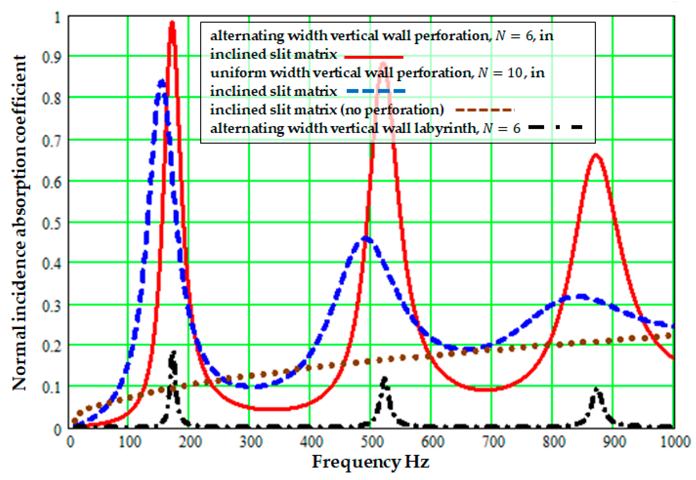
A second consequence of the extra tortuosity associated with alternating the width of a vertical-wall labyrinthine slit is that a narrow-band low-frequency absorption peak is predicted even if it is used to perforate a relatively low-flow-resistivity and low-porosity matrix. This is illustrated in Figure 8. A low-frequency high-absorption peak at 200 Hz is predicted for a 6-fold alternating-width vertical-wall labyrinthine slit perforation in a 4.5 cm thick matrix containing 0.3 mm wide slits at 60° to surface normal with a porosity of only 0.1. A lower absorption peak at 220 Hz is predicted for a 10-fold 3 mm wide labyrinthine perforation in the same porous matrix. 0.3 mm wide micro-slits are readily manufacturable using a commonly available 3D printing method [10].
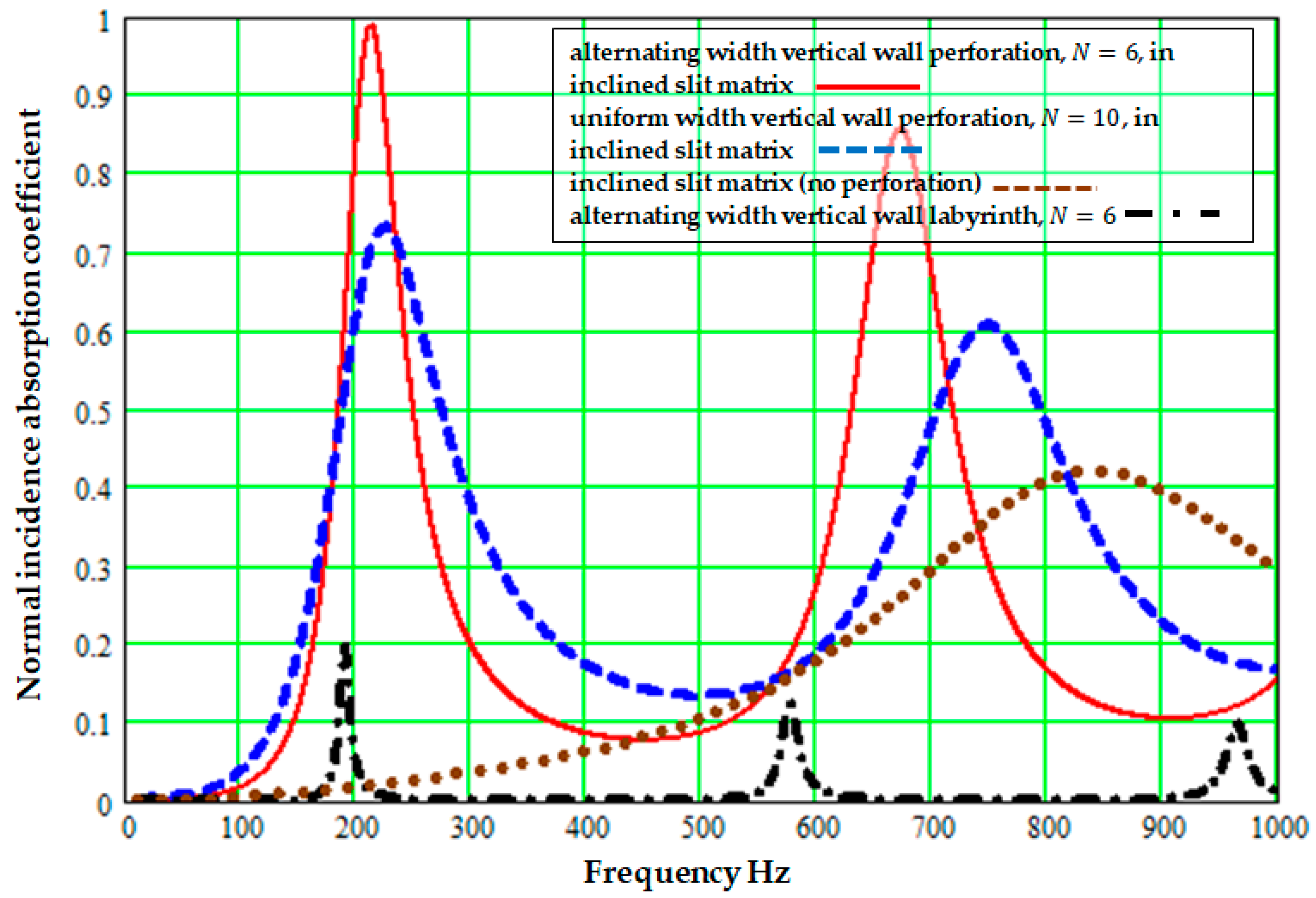
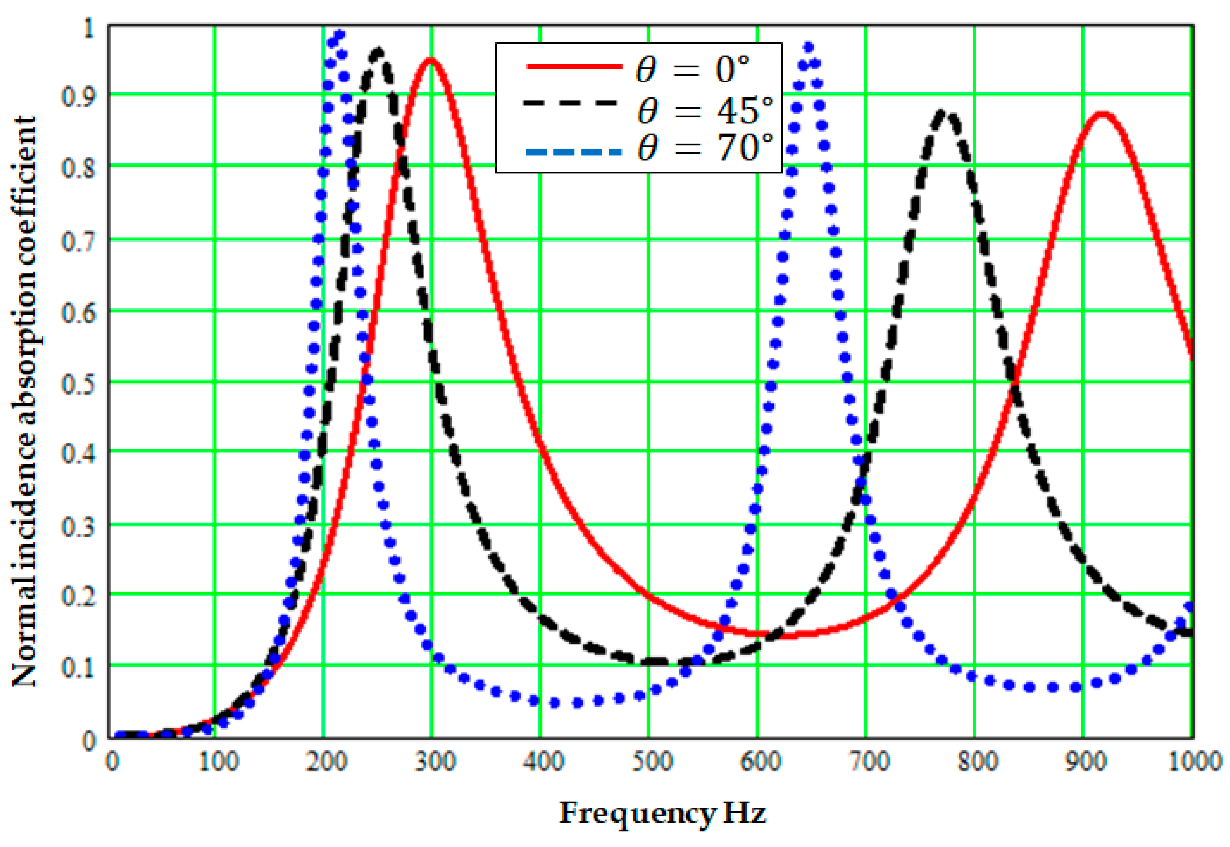
If an alternating-width labyrinthine slit perforation is created in a lower-flow-resistivity and low-porosity matrix, then the tortuosity of the porous matrix is predicted to have a strong influence. This is illustrated by the predictions in Figure 9, where, keeping all other parameters the same, increasing the tortuosity of the matrix from 1 (matrix slits normal to surface) to 8.55 (matrix slits inclined at 70° to the normal) reduces the frequency of the lowest-frequency absorption peak from 300 to 210 Hz.

5. Concluding Remarks

Analytical approximations to the acoustical effects of horizontal- or vertical-wall labyrinthine slit perforations in a high-flow-resistivity porous matrix have been developed and used to predict potentially useful low-frequency narrow-band sound absorption from hard-backed layers with deep sub wavelength thickness. The predicted effects combine the influences of labyrinthine slit tortuosity and pressure diffusion.
Both horizontal- and vertical-wall labyrinthine slits with constant width can have very high values of tortuosity. However, vertical-wall labyrinthine perforations with alternating widths offer even higher tortuosity due to the changes in slit cross section, thereby enabling predictions of useful low-frequency performance using fewer slit folds or a lower-flow-resistivity and lower-porosity matrix than would be needed for a labyrinthine slit perforation of constant width.
The predictions reported in this paper are based on zigzag approximations of the tortuous paths in the labyrinths. Comparisons of the example estimates in Table 2 based on zigzag and centre line paths in various labyrinthine slits suggest that estimates that correspond to paths along the centre lines could be at least 25% higher than the zigzag path estimates.
More accurate tortuosity estimates could be established by numerical simulations of steady inertial fluid flow in relevant configurations. These and other numerical simulations outlined elsewhere [11] will be used, together with measurements on 3D-printed examples, to investigate the accuracy of the analytical approximations for absorption coefficient spectra due to labyrinthine slit perforations in porous materials.
Similar approximations could be derived for the acoustical properties of a three-dimensional rectangular labyrinthine perforation in rigid-porous matrix which has the potential for yet greater streamline path tortuosity and, thereby, even lower-frequency narrowband absorption peaks if used in a thin hard-backed porous layer.

Funding

This research received no external funding.

Institutional Review Board Statement

Not applicable.

Informed Consent Statement

Not applicable.

Conflicts of Interest

The author declares no conflict of interest.

References

  1. Atalla, N.; Sgard, F.; Olny, X.; Panneton, R. Acoustic absorption of macro-perforated porous materials. J. Sound Vib. 2001, 243, 659–678. [Google Scholar] [CrossRef]
  2. Sgard, F.; Only, X.; Atalla, N.; Castel, F. On the use of perforations to improve the sound absorption of porous materials. Appl. Acoust. 2005, 66, 625–651. [Google Scholar] [CrossRef]
  3. Tang, W.; Ren, C. Total transmission of airborne sound by impedance-matched ultra-thin metasurfaces. J. Phys. D Appl. Phys. 2017, 50, 105102. [Google Scholar] [CrossRef]
  4. Krushynska, A.O.; Bosia, F.; Pugno, N.M. Labyrinthine acoustic metamaterials with space-coiling channels for low-frequency sound control. Acta Acust. United Acust. 2018, 104, 200–210. [Google Scholar] [CrossRef] [Green Version]
  5. Attenborough, K. Microstructures for lowering the quarter wavelength resonance frequency of a hard-backed rigid-porous layer. Appl. Acoust. 2018, 130, 188–194. [Google Scholar] [CrossRef]
  6. Olny, X.; Boutin, C. Acoustic wave propagation in double porosity media. J. Acoust. Soc. Am. 2003, 114, 73–89. [Google Scholar] [CrossRef] [PubMed]
  7. Xin, F.; Ma, X.; Liu, X.; Zhang, C. A multiscale theoretical approach for the sound absorption of slit-perforated double porosity materials. Comp. Struct. 2019, 223, 110919. [Google Scholar] [CrossRef]
  8. Attenborough, K. Macro- and Micro-structure designs for porous sound absorbers. Appl. Acoust. 2019, 145, 349–357. [Google Scholar] [CrossRef] [Green Version]
  9. Chevillotte, F.; Perrot, C.; Panneton, R. Microstructure based model for sound absorption predictions of perforated closed-cell metallic foams. J. Acoust. Soc. Am. 2010, 128, 1766–1776. [Google Scholar] [CrossRef] [PubMed] [Green Version]
  10. Opiela, K.C.; Zieliński, T.G.; Attenborough, K. Manufacturing, modeling, and experimental verification of slitted sound absorbers. Proc. ISMA 2020, ID451. [Google Scholar]
  11. Zieliński, T.G.; Venegas, R.; Perrot, C.; Cervenka, M.; Chevillotte, F.; Attenborough, K. Benchmarks for microstructure-based modelling of sound absorbing rigid-frame porous media. J Sound Vib. 2020, 483, 115441. [Google Scholar] [CrossRef]
Figure 1. (a) Unit cells containing a single labyrinthine slit, formed by walls either (a) parallel to or (b) normal to the insonfied surface, detailing the associated dimensions, zigzag approximations to streamline paths (broken lines) and path lengths.
Applsci 11 03299 g001
Figure 2. (a) Plot of the modulus of the pressure diffusion correction function, | F d ( ω ) | , against frequency for a vertical-wall labyrinthine slit ( w = 1 mm, b = 3 mm, l = 45 mm, N = 10) in a slanted slit pore matrix (0.04 mm wide slits at 70° to the normal, porosity 0.9). (b) Plot of the corresponding imaginary part of the double porosity bulk modulus.
Applsci 11 03299 g002
Figure 3. Normal incidence absorption spectra predicted for 5.8 cm thick hard-backed porous layers of rockwool and melamine foam described by the JCAL parameters listed in Table 1 with horizontal-wall labyrinthine slit perforations ( w = 5 mm, b = 5.5 mm, l = 40 mm, N = 5 as shown on the right). Also shown (dash dot lines) are predictions for these materials without perforation.
Applsci 11 03299 g003
Figure 4. Normal incidence absorption spectra predicted for a 5 cm thick hard-backed inclined slit matrix (0.04 mm wide slits at 70° to the normal, porosity 0.9) with (solid lines) and without (dotted lines) (a) a horizontal-wall labyrinthine slit perforation ( w = 2 mm, b = 4 mm, l = 40 mm, N = 8) and (b) a vertical-wall labyrinthine slit perforation ( w = 1 mm, b = 3 mm, l = 45 mm, N = 10). The dash-dot lines represent predictions for the labyrinthine slit perforations in a non-porous solid matrix.
Applsci 11 03299 g004
Figure 5. Normal incidence absorption coefficient spectra predicted for 0.05 m thick hard-backed layer composed from a inclined slit matrix (0.04 mm wide slits at 70° to the normal, porosity 0.9) with (a) varying wall length in a horizontal-wall labyrinthine slit perforation ( w = 1 mm, b = 5.1 mm,   N = 8); l = 0.04 m (solid line), l = 0.08 m (dotted line), l = 0.12 m (dash-dot line) or (b) varying slit folding number in a vertical-wall labyrinthine slit perforation ( w = 1 mm, b = 3 mm, l = 45 mm, N = 5 (continuous line), N = 10 (blue dotted line), N = 15 (black broken line). The low absorption dash-dot lines represent predictions for the respective labyrinthine slit perforations in a non-porous solid matrix.
Applsci 11 03299 g005
Figure 6. A vertical-wall labyrinthine slit with alternating widths.
Applsci 11 03299 g006
Figure 7. Normal incidence absorption coefficient spectra predicted for 0.045 m thick hard-backed layers consisting of either alternating width ( w = 1 mm, b = 3 mm, l = 40 mm, δ = 7, N = 6, continuous line) or constant width ( w = 1 mm, b = 3 mm, l = 40 mm, N = 10, broken line) vertical-wall labyrinth in a slit pore matrix (0.04 mm wide slits at 70° to the normal, porosity 0.75). The dash-dot line is the prediction for the same non-uniform labyrinthine perforation in a non-porous solid and the dotted line is the prediction for the slit pore medium (no perforation).
Applsci 11 03299 g007
Figure 8. Normal incidence absorption coefficient spectra predicted for 0.045 m thick hard-backed layers consisting of either an alternating width ( w = 1 mm, b = 3 mm, l = 40 mm, δ = 8, N = 6, continuous line) or a constant width ( w = 1 mm, b = 3 mm, l = 40 mm, N = 10, broken line) vertical-wall labyrinthine slit in a slit-pore matrix (0.3 mm wide slits at 60° to the normal, porosity 0.1). The dash-dot line is the prediction for the same labyrinthine slit perforation in a non-porous solid and the dotted line is the prediction for the slit pore medium alone (no perforation).
Applsci 11 03299 g008
Figure 9. Normal incidence absorption coefficient spectra predicted for an alternating-width vertical-wall labyrinthine perforation ( w = 2 mm, b = 4.5 mm, l = 41 mm, δ = 6, N = 6) in a 0.05 m thick hard-backed micro-slit matrix (porosity 0.1, 0.4 mm wide slits) in which tortuosity is varied through slit inclination at 0° (continuous line) or 45° (broken line) or 70° (dotted line) to the normal.
Applsci 11 03299 g009
Table 1. JCAL model parameter values assumed for rockwool [2] and melamine foam [9].
Material/Parameter Ω m σ m kPa   s   m 2 Tk0 m2Λ μm Λ μm
rockwool0.941352.13.3 × 10−949166
melamine foam0.99121.011.5 × 10−9100400
Table 2. Example lower and upper estimates of labyrinthine slit tortuosity.
w mm b mm l mm N T H Z T H C T V Z T V C δ T A W Z T A W C
55.54059.2511.213.119.9429.340.3
1340686.890.228.534.2784.1102.2
134510114.9119.181.295.68264.5353.4
Publisher’s Note: MDPI stays neutral with regard to jurisdictional claims in published maps and institutional affiliations.

