Abstract
The determination of the ultimate shear capacity and the identification of the corresponding load-carrying mechanisms of concrete members without shear reinforcement has been an ongoing research topic for over 100 years. Based on a full mechanical model, the Shear Crack Propagation Theory (SCPT) enables to analyze and understand the ever-changing interplay of crack propagation, evolution of stresses at the crack tip and in uncracked concrete parts, as well as the activation of shear transfer actions within the growing shear crack during the entire loading process. In this paper, selected experimental investigations for further validation of the SCPT are presented. These beam shear test results are then compared to the theoretical results emerging from the SCPT algorithm. Finally, the evolution of different shear transfer actions (e.g., aggregate interlock and dowel action) during the entire loading process is evaluated and discussed.
1. Introduction and Research Significance
In the design and assessment of reinforced concrete (RC) structures, the shear design is typically one of the governing aspects. RC slabs and beams without shear reinforcement are examples of structural members that must fulfil the requirement of shear capacity on the one hand and the need for efficient construction on the other hand. Although linear members in structural applications always require a minimum amount of shear reinforcement according to the most design provisions, beam specimen without shear reinforcement are frequently used for scientific investigations on the shear behavior of one-way slabs, as they allow a rather easy inspection and measurement of cracking phenomena including shear crack propagation on their lateral surfaces. Previous evaluations of experimental investigations on slabs and beams with similar boundary conditions have showed that beams can be regarded as a slab segment and, thus, indicated that the shear capacity of a member does not depend on its width [1,2]. However, despite significant efforts in the past, there is still no general agreement in the scientific community on the exact phenomena governing the shear strength, which complicates the consensus on generally accepted design codes. Therefore, it is important to provide new characterization methods leading to a deeper insight into the shear failure process and providing the basis for an efficient design in terms of reduced material consumption, enhanced service life and increased reliability.
Seeking a mechanical solution to the riddle of shear in beams and slabs without shear reinforcement, a lot of different models have been developed by many researchers during the last century. Starting in the 1960s with rather simple empirical models [3], the parameters concrete strength and reinforcement ratio, as well as beam depth and width, were acknowledged as the most relevant parameters affecting the shear strength [4]. Later on, the size effect was studied and included in empirical formulas [5,6,7]. The influence of the aggregate size [8], fracture energy [9] and shear slenderness [3] have also been identified by different researchers. For a long time, the primary intention of many experimental campaigns was to investigate specific shear strength parameters and their implementation in empirical formulas instead of identifying and analyzing the actual shear transfer mechanisms behind these parameters. Present day models try to get a deeper understanding of the mechanical background of shear behavior [10,11,12]. Due to today’s access to refined experimental and numerical methods, such as new high-resolution measurement techniques, it is possible to track the entire crack kinematics or to determine the transferred stresses along the crack from constitutive relations. As a result, various previously postulated effects of shear transfer were proven by measurements in recent years. Such methods have been used by Kollegger, Cavagnis and Mari and Cladera [13,14,15], for instance.
In contrast to the empirical approaches, analytical models attempt to address explicitly the elementary effects controlling the shear failure process. Some approaches consider one specific shear transfer action as governing to derive a physically based analytical model. For instance, the models by Zink and Zararis identified the shear transferred by the compression chord as the most significant shear contribution [16,17]. Other authors, e.g., Vecchio and Collins, considered the aggregate interlock mechanism as the governing action in their compression field theory [11,18]. Yang and Walraven [19,20] also emphasized the role of the aggregate interlock. In their model, the shear strength was coupled with a critical shear displacement in the crack, accounting for the fact that the shear failure was triggered by the development of a delamination crack at the level of flexural reinforcement. Another class of modeling approaches primarily addressed the residual tensile stress of concrete after cracking based on fracture mechanic concepts [6,7]. Other approaches were developed based on the upper-bound theorem of the limit analysis enhanced with the effect of concrete cracking [21].
An approach involving various potential shear transfer actions was proposed by Tue [22] by connecting the tips of adjacent flexural cracks with a shear crack by applying a tensile stress criterion. Another model comprising several shear transfer actions was suggested by Mari and Cladera [15], emphasizing the effect of the compression chord, in particular. In the Critical Shear Crack Theory by Muttoni and Ruiz [23], the failure criterion accounted for the effects of residual tensile stress, aggregate interlock and dowel action in the shear crack. The most comprehensive model also considering the effect of the compression zone in a kinematically consistent manner was presented by Reineck [24]. The model is based on a free body diagram of cracked concrete teeth and postulates an equilibrium between the internal shear stress resultant and the external shear force. The shear strength is determined using an iterative procedure.
Despite these research efforts, there is still a remarkable number of open research questions. In the authors’ opinions, the best way to gain a deeper insight into the shear of RC members is to model the entire shear response instead of focusing on the failure state. Staring from this ambition, a new theory called Shear Crack Propagation Theory (SCPT) was developed by Classen [25] to analyze the ever-changing interplay of crack propagation, evolution of stresses at the crack tip and in uncracked concrete parts of the control section, as well as the activation of shear transfer actions within the growing shear crack during the entire loading process.
The localization and propagation of cracks through the shear zone of RC members poses several challenging questions that have been addressed in the context of finite element modeling. For example, promising approaches have been proposed by Sucharda [26], Malm [27] and Herbrand [28]. Additional finite element (FE) and discrete element approaches providing reasonable results are presented in [29,30,31,32], as well as in [33], giving a good prediction of the shear capacity of large slabs, indicating that size-dependent effects are well-covered. A specific challenge in the numerical modeling of shear in concrete is the consideration of aggregate interlock and mixed-mode behavior, which can neither be captured realistically by simplified approaches using shear retention factors (reduction of the shear modulus) [34] nor using micro-planes [35]. A new smeared crack formulation, called the fictitious rough crack model (FRCM) [36], was proposed to account for the shear transfer across cracks and mixed mode fracture of concrete, which combines a multiaxial material model, including tension-softening (mode I), with rough crack shear transfer laws (mode II) and superposes the emerging shear and normal stresses of both mechanisms in the crack in order to numerically represent the mixed mode concrete behavior.
However, in contrast to such numerical approaches using FE modeling, the ambition of the research proposed in this paper is not only to mimic the experimental behavior as close as possible and to isolate and classify the relevant parameters of the shear zone behavior but to provide a comprehensible, mechanical idea of the interaction of the involved mechanisms of shear behavior that allow to derive simplified and easy-to-use engineering models based on a sound mechanical theory. In general, models based on discrete crack kinematics, as well as FE models, are able to give a reasonable and good prediction of the ultimate shear capacity and the crack development in simply supported beams. However, the SCPT in particular is motivated to explain the mechanical background of the shear in RC members on a more general basis for developing practice-related design tools.
Overall, the shear cracking behavior and failure of RC members was studied in numerous experimental campaigns in the past. However, there are no test campaigns known so far where the RC beams and the corresponding test specimens for characterizing the constitutive relations (tensile behavior, aggregate interlock and dowel action) were produced from the same material set. As a consequence, constitutive relations from literature were used, yielding a significant scatter in the theoretical evaluations due to inconsistent material properties [14]. To analyze the contribution and activation of different shear-carrying mechanisms (e.g., aggregate interlock, dowel action) and to analyze the total shear capacity of RC members without shear reinforcement, especially during the entire loading process, beam tests, as well as component tests with identical material properties, were performed at the Institute of Structural Concrete (IMB) at RWTH Aachen University.
The paper at hand presents one specific beam shear test, providing sophisticated measurement results applied for the comparison and discussion of the SCPT model.
2. Shear Crack Propagation Theory (SCPT)
The SCPT intends to provide a deeper understanding of shear in beams and slabs without shear reinforcement through analyzing the entire shear response (load history) of a member instead of solely focusing upon the fracture state. To this end, the mechanical theory considers crack propagation through the shear zone and is based on the requirement of the equilibrium for the bending and shear stress resultants in an intermediate state of the shear crack propagation. Besides the equilibrium of the forces within every load increment, the SCPT accounts for the material constitutive behavior, as well as the compatibility of the kinematic behavior.
The shear failure process of RC members without shear reinforcement includes several interacting effects of the material behavior. These elementary effects within the shear critical region of a member are exemplarily sketched in Figure 1a. Effect (1) is the crack localization within the fracture process zone (FPZ). Effect (2) describes the crack propagation due to the increasing load. Both effects are interrelated with the biaxial concrete stresses at the propagating crack-tip. The biaxial stress state depends on the shear transfer through bending of the concrete teeth between adjacent flexural shear cracks, also known as cantilever action (3). Here, bending of the concrete teeth is mainly influenced by the difference of tension in the longitudinal reinforcement between two adjacent interacting cracks (called ΔFs) and the equilibrium conditions of the forces within the shear cracks at both sides. Assuming that all forces within both shear cracks are rotating around an assumed center of rotation, located in the middle between the two crack tips, the vertical stresses resulting from this (cantilever action) are called σz and are taken into account when calculating the biaxial stress state at the crack tip. With increasing the vertical stress σz, the crack propagation angle decrease. Effect (4) represents the shear transfer in the uncracked part of the concrete above the crack tip in combination with the effect of direct strutting. Effect (5) is the shear stress transfer resulting from aggregate interlock between two crack faces, while effect (6) comprises the transverse stiffness and strength of the flexural reinforcement and concrete cover known as the dowel action. Finally, effect (7) describes the crack bridging actions including tension stiffening, as well as bond behavior and delamination of the flexural reinforcement.
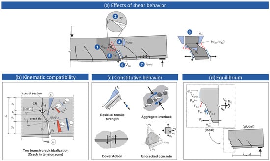
Figure 1.
Overview of the Shear Crack Propagation Theory (SCPT) algorithm: (a) elementary effects of the shear behavior, (b) idealized crack geometry and fracture kinematics, (c) constitutive relations and (d) shear contributions and equilibrium.
To combine all the identified effects (1)–(7) relevant for RC members without shear reinforcement in one all-encompassing algorithm, the member is discretized as a system of interacting concrete teeth that are separated from each other by discrete propagating shear cracks but connected by a continuous concrete body representing the compression zone and uncracked tension zone (“backbone”) (Figure 1a). In the next step, a biaxial shear crack propagation criterion (cohesive crack approach by Hillerborg [37] combined with Kupfer’s fracture criterion [38]) is implemented to determine the crack propagation angle and crack extension, as well as the continuity of stresses at the transition between the compression zone and crack (vertical crack tip stresses resulting from cantilever action serve as the input information) (Figure 1a). The crack propagation criterion delivers the shear crack path defining the control section to formulate the compatibility and equilibrium conditions.
The stress and strain fields within this control section are decomposed into four parts–namely the compression and uncracked tension zone, fracture process zone, frictional zone and crack bridging and dowel action zone. Considering the compatible kinematic model illustrated in Figure 1b allows assessing the strains in uncracked concrete parts and the flexural reinforcement, as well as the local opening and sliding deformations in the propagating shear crack based on the rotational degree of freedom φ. The center of the rotation varies within the shear failure process corresponding to the propagation of the crack tip with the increasing load. The calculated local deformations and strains, in turn, serve as the input values for the constitutive relations.
In each zone, the application of constitutive relations allows calculating the contribution of the different shear transfer actions along the propagating crack (e.g., residual tensile stress transfer, aggregate interlock and friction along the sliding crack interfaces and crack bridging, including dowel action). Furthermore, the integration of horizontal normal stresses and shear stresses in uncracked regions of the control section allows to determine all transferred normal and shear forces in the continuous concrete (Figure 1c). The further surrounding sections of the member are assumed as rigid.
In summary, such an idealization of the shear crack provides the necessary and sufficient conditions of the equilibrium (Figure 1d) and kinematic compatibility to devise an incremental algorithm that allows to calculate the shear crack extension (crack propagation angle and crack propagation length), deformations and strains, as well as all internal forces (e.g., the overall shear force Vi, including all the shear contributions) corresponding to a prescribed load increment. The position of the governing (critical) shear crack along the beam axis has to be determined iteratively. To this end, various crack positions defined through λcs × d (Figure 1d), which is the distance between the center line of the support and the root of the shear crack, have to be checked. The crack position delivering the minimum shear capacity is the critical crack position. With regard to the experimental results presented in this paper, the critical shear crack position is marked in Figure 5. A detailed description of the mechanical background of the SCPT can be consulted in reference [25].
In the future, the SCPT algorithm will also be extended to the application of shear reinforcement. Accordingly, the equilibrium conditions will be extended, the changes in kinematics will be considered and the additional failure mode of a compression strut failure will be implemented. Furthermore, the activation of shear reinforcement and, thus, the effective steel stress will be in the focus of future studies.
3. Experimental Investigations
To evaluate and validate the SCPT and to deeply analyze the shear failure behavior, an extensive experimental program with systematically varying boundary conditions (e.g., change in the flexural reinforcement ratio or maximum aggregate size) has been started at the Institute of Structural Concrete at RWTH Aachen University. The initial experimental results of a beam shear test and a first comparison with the SCPT are presented in this publication, while a more comprehensive evaluation of the entire test campaign will be published in the future.
The investigated beam specimen B1 had a total length of L = 4700 mm and a rectangular cross-section of b × h = 320 × 350 mm. To allow for two shear subtests B1-1 and B1-2 on beam B1, the test setup consisted of a simply supported beam with a cantilever so that the unloaded cantilever from the first shear subtest was used as the undamaged section for a second shear subtest (Figure 2). Due to this test set-up, the middle section of the beam could be used twice to save resources (e.g., concrete and reinforcing steel as well as formwork). In addition to these economic advantages, the concept of conducting subtests allows for ensuring that identical concrete and reinforcing steel material parameters are used in two shear tests. Accordingly, each shear test was performed as a three-point bending test with a total span of L = 2800 mm. The load F was applied with a distance a = 1300 mm from the left support so that the shear failure was expected to occur at this end of the beam. To prevent an unintended shear failure in the other end of the shear span, stirrups as shear reinforcement were applied in the middle section of the beam. The shear slenderness ratio was a/d = 4.33 and the bending slenderness was L/h = 8. The flexural reinforcement consisted of five bars with Ø = 16 mm resulting in ρl = 1.05%. The yield strain was εs = 2.89‰, with a Young’s modulus of Es = 199 GPa providing a yield strength of fy = 575 MPa. In the compression zone, two bars with Ø = 10 mm were used for practical and detailing reasons. The nominal concrete cover of the longitudinal bars was cnom = 40 mm, resulting in a nominal effective depth d = 302 mm.
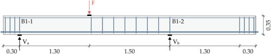
Figure 2.
Side view of test specimen B1, including the reinforcement arrangement.
A normal-strength concrete with a maximum aggregate size dg = 16 mm was used. At the day of testing, the properties of the hardened concrete were identified in the material tests summarized in Table 1. The concrete compressive strength was determined on 150-mm cubes (fcm,cube) and on concrete cylinders with d/h = 150/300 mm (fcm,cyl), according to reference [39]. The splitting tensile strength (fct,sp) was tested on shortened cylinders (d/h = 150/150 mm). The mean modulus of elasticity (Ecm) was also tested on cylinders (d/h = 150/300) with method “B”, according to reference [40].

Table 1.
Material properties of the hardened concrete at the day of testing.
The test setup of the simply supported beam with a cantilever is shown in Figure 3. The load was applied using a 630-kN hydraulic jack. To reduce the local stress concentration, a steel plate (100 × 320 × 10 mm) was used beneath the load application and at the supports. Additionally, a roller was placed under one support to allow for a free horizontal movement. Both supports were able to allow for rotations.
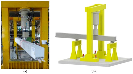
Figure 3.
Test setup and instrumentation: (a) test set-up and (b) 3D view of the test set-up.
The specimen was tested under quasi-static conditions with a load rate of 5 kN/min until failure. For up to 60–70% of the expected maximum shear capacity, the load was introduced load-controlled. After that, the load was applied deformation-controlled until a significant load drop indicated a clear failure. At predefined load steps–usually 12.5% of the expected failure load, the test was paused to mark new cracks and document the crack pattern.
The vertical displacements WD1–WD3 of the beam were measured through three linear variable displacement transducers (LVDTs) arranged in the load axis and in the middle between the load axis and each support (Figure 4). In the section with the expected shear failure, three diagonal LVDTs (Wd1–Wd3), as well as three horizontal LVDTs (Wh1–Wh3) were used to track the deformations caused by the shear crack formation (Figure 4). Apart from these LVDT measurements at one side of the beam, a 3D-digital image correlation (DIC) measurement system was used to observe the shear crack formation at the backside of the beam. In addition to the external measurements, the strain gauges and fiber optical sensors (FOS) at the flexural reinforcement bars were used as the internal measurement. In general, the following evaluation only focuses on selected measurement results that are relevant for the validation and the discussion of the SCPT.
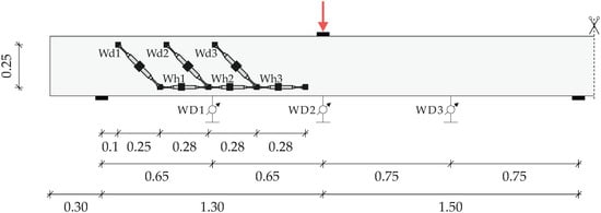
Figure 4.
External measuring instrumentation.
4. Results of Experimental Investigations
4.1. Crack Pattern and Failure Crack at Ultimate Load
For a detailed comparison between the experimental results and SCPT analysis, it is important to have detailed information not only on the final crack pattern but even more on the crack propagation during the loading process. The root of the shear crack serves as an input parameter for the SCPT algorithm and is therefore of major importance.
Both subtests B1-1 and B1-2 showed a similar crack pattern regarding the major flexural shear cracks (Figure 5). In both cases, the first flexural cracks spread from the middle of the beam to the supports. The resulting flexural shear cracks propagated nearly vertically up to the mid-depth of the beam. Then, the inclination was significantly reduced from this height and the shear cracks became flatter. With the increasing load and thus decreasing shear crack inclination, the formation of a decisive bending shear crack was observed. Whereas the root of the failure crack in subtest B1-1 was identified at a distance of 2.67 × d from the support, subtest B1-2 revealed an increased distance of 3.54 × d (Figure 5).
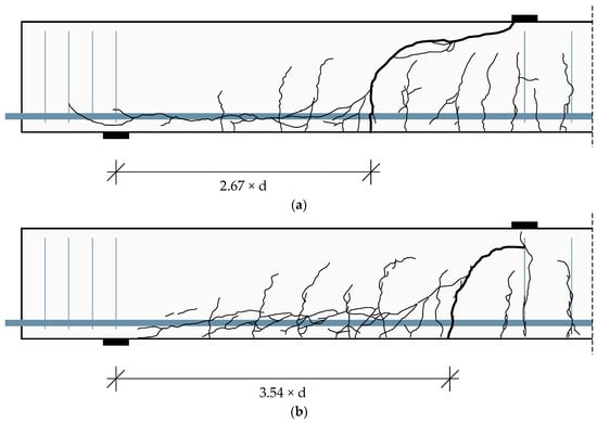
Figure 5.
Experimental crack pattern at the state of failure: (a) B1-1 with Vu,a = 104.8 kN and (b) B1-2 Vu,a = 105.1 kN.
For both subtests, a brittle failure after reaching the maximum load, indicated by a significant load drop, was observed revealing a flexural shear failure. The failure loads are given in Table 2 and reveal a similar level of ultimate capacity for B1-1 and B1-2.
Table 2.
Ultimate load Fu and resulting shear force at the support Vu (self-weight neglected).
4.2. Load Deflection Behavior
The load deflection curves until reaching the maximum failure load are displayed in Figure 6. Comparing the vertical deflection in the measuring points WD1–WD3, it is obvious that both subtests exhibited nearly identical and, overall, very symmetrical deformation behavior.
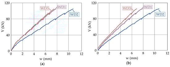
Figure 6.
Shear force—deflection curve: (a) B1-1 and (b) B1-2.
4.3. Shear Crack Kinematics and Concrete Strains in Compression Zone
In Figure 7a, the shear crack opening wreinf resulting from the DIC measurements (blue curve) at the height of the longitudinal reinforcement bars in the tensile zone is plotted against the total shear force Vu,a revealing a nearly linear increase up to wreinf = 0.4 mm. In Figure 7b, the maximum concrete compressive strain at the top fiber of the uncracked zone derived from 3D-DIC is shown (blue curve). Close to the failure load, a significant increase of the concrete compressive strains was detected, indicating plastic deformations.
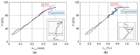
Figure 7.
Experimental and calculated (SCPT) results for: (a) the crack opening wreinf at the height of the reinforcement layer and (b) the maximum concrete compressive strain εtop in the top fiber of the uncracked zone.
A slight oscillation of both curves starting after exceeding a shear force of approx. 70 kN is noticeable. At this loading stage, the measuring rate of the DIC-system was changed from 0.5 Hz to 1 Hz, resulting in more measured points and a rough curve. The period of one minute prior to failure was tracked with a measuring rate of 5 Hz to monitor the moment of failure in detail by using a ring buffer system.
5. Discussion and Comparison to SCPT Results
In the following section, the application of the Shear Crack Propagation Theory (SCPT) on the presented beam shear tests is evaluated and discussed. The focus is exclusively on subtest B1-1, since the results for both subtests (e.g., shear crack geometry, deflection behavior and ultimate capacity) are nearly similar, as concluded in Section 4.
5.1. Comparison of the Maximum Load
The experimental shear failure load of B1-1 (Vu) is compared to the ultimate shear capacity according to the SCPT (Vu,SCPT) and to the current EC2 (Vu,EC2) [41] (Table 3). For calculation of the shear capacity according to EC2, a factor CRm,c = 0.192 was used to account for a mean instead of a characteristic value [42] to determine the ultimate capacity. The maximum shear force at failure according to the SCPT is taken as the load when the maximum stress σzo is reached and no further equilibrium can be found. At this point, a significant reduction of the shear capacity in the uncracked zone also took place, and the decreasing crack propagation angle β was not able to compensate the reduction of the shear stress capacity due to vertical stresses σzo at the crack tip. Detailed information on the shear stress distribution and the influence of propagating shear crack angles may be taken from reference [25]. With regards to the values shown in Table 3, it is stated that both the calculated capacities (SCPT and EC2) give a good prediction of the ultimate shear capacity resulting from the experimental test.
Table 3.
Comparison of the experimental shear failure load Vu (self-weight neglected) with calculated shear failure loads according to the Shear Crack Propagation Theory (SCPT) and current EC2.
5.2. Shear Crack Geometry
Since the SCPT allows to determine the shear crack development, a comparison of this calculated failure shear crack geometry with the experimentally recorded shear crack patterns resulting from the manual documentation, as well as automatized DIC measurements is conducted (Figure 8). Slight differences in the two experimentally derived shear crack patterns for subtest B1-1 are detected due to the measuring at opposite sides of the beam. Overall, the calculated shear crack geometry by using the SCPT shows an excellent agreement with the actual failure shear crack. While both shear cracks are congruent until approx. the mid-depth of the beam, a marginal deviation in the inclination of both cracks is detected for loads close to shear failure (Figure 8).
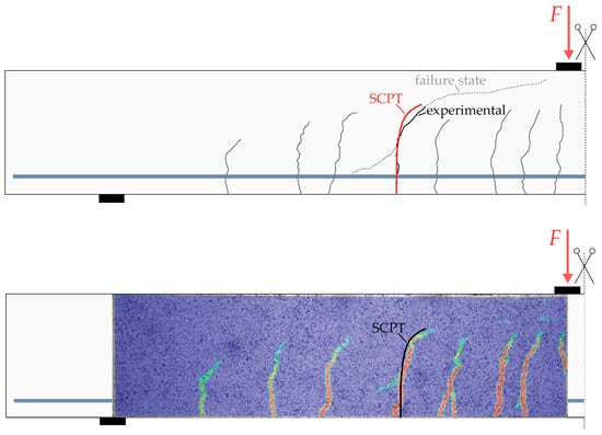
Figure 8.
Comparison of the calculated SCPT failure shear crack with the experimentally obtained crack pattern: (top) marked crack pattern and (bottom) digital image correlation (DIC) measurements at the opposite side.
The comparison in Figure 8 clearly demonstrates that the SCPT is capable of calculating a well-matching shear crack development purely based on the implemented constitutive laws and kinematic relationships, without an empirical addition. In any state of crack propagation before reaching the maximum failure load and, thus, at each load level, the information about the geometry of the theoretical shear crack is available.
5.3. Shear Crack Kinematics and Concrete Strains in Compression Zone
With regards to Figure 7 and the measured developments of the crack opening wreinf and maximum concrete compressive strain εtop, the corresponding SCPT results generally show a very good agreement when compared to the DIC curves. For shear loads larger than V ≈ 95 kN, the experimentally obtained crack openings and concrete compressive strains started to increase, caused by a larger shear crack rotation. However, the calculated SCPT values do not show this change in slope for both measurements due to linear constitutive laws used in the SCPT algorithm (e.g., linear elastic behavior of the concrete in compression and tension).
Apart from this deviation close to the failure load, it is stated that the SCPT in its form today using the linear constitutive behavior of concrete and linear aggregate interlock behavior [43] is capable to track the crack kinematics up to a point prior to failure, where the nonlinear behavior sets in, which may be initiated by a redistribution of stresses within the shear crack.
6. Analysis of Shear Transfer Actions
6.1. General
The SCPT is based on an iterative procedure to determine the crack propagation and the corresponding stresses or forces, respectively, in the considered shear crack and provides results for the entire loading process up to the failure. As a matter of fact, the SCPT is able to deliver information on the total and relative stress contributions of all the shear-carrying load mechanisms. In the following, the SCPT results for subtest B1-1, which are shown in Figure 9, regarding the interplay of different shear transfer actions in the failure process are summarized and reflected. The SCPT algorithm according to reference [25] is used without any further modifications. Based on these results, suggestions for further adjustments, extensions and potential refinements of the SCPT are proposed.
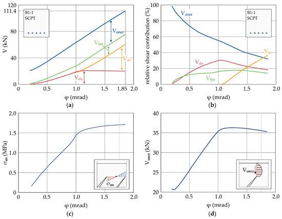
Figure 9.
SCPT analysis results for the critical shear crack of subtest B1-1 with regards to the shear crack rotation φ: (a) shear force—rotation relationship, (b) relative contribution of the shear transfer actions, (c) development of the vertical crack tip stress σz0 and (d) absolute shear force Vuncr in the uncracked zone.
Apart from the resulting total shear force, Figure 9a also contains the cumulated contributions of all the considered shear transfer actions, while Figure 9b shows the relative contribution of the different shear transfer actions related to the total transferred shear force. Both plots allow quantifying the magnitude and importance of all shear transfer actions according to the SCPT and to follow the evolution of these shear transfer mechanisms during the entire loading process.
6.2. Uncracked Concrete Zone
The shear transfer in uncracked concrete (compression zone and uncracked tension zone) derived from SCPT is the most significant load-carrying mechanism at low load levels simply due to large uncracked concrete parts.
Up to 50% of the ultimate load, more than half of the total shear capacity, is provided by the shear contribution of the uncracked concrete parts. At higher load levels, this contribution becomes less significant, since the propagating crack tip reduces the uncracked concrete area. With increasing load level, the vertical crack tip stresses resulting from bending of concrete teeth (cantilever action) will also increase (Figure 9c). At this point, two counteraction effects come into play: Due to the flattening crack propagation angle β, the transferrable shear stresses increase, but at the same time, the vertical crack tip stress σzo reduces the transferrable shear stresses in the uncracked zone. Taking a look at Figure 9d, it is displayed that the resulting shear force Vuncr increases until a rotation of φ ≈ 1.1 mrad and then slightly decreases until the point of failure is reached.
6.3. Fracture Process Zone
The shear contribution of the fracture process zone (FPZ) according to SCPT develops in a similar way to the transferred total shear force. It is shown in Figure 9b that, after a rather steep increase of the FPZ contribution until 15% of the total shear capacity, the contribution persists at a level of 15–20% during the further loading process. The force of the FPZ can be divided into a vertical and a horizontal component. The vertical component of the FPZ resultant increases with flattening shear crack inclination (approx. after φ = 1.0 mrad). Obviously, the higher effectivity of the shear transfer at flat shear crack inclinations compensates for a potential slight reduction in the residual stress transfer for the increasing crack rotations. In conclusion, the FZP contribution to the total shear force capacity is small at low load levels, where the shear crack inclination is rather steep and the concomitant vertical component of residual tensile stresses is also small. Whereas, at higher load levels, the vertical component of FPZ becomes more effective, since the shear crack propagation angle becomes flatter. It is interesting to note that shear strength models, which assume a fixed center of rotation at the crack tip rather than considering shear crack propagation, reveal an inverse behavior suggesting a decreasing shear contribution of the FPZ for the increasing load levels [23,44,45]. For the increasing load levels, this simplifying assumption of a fixed center of rotation at the crack tip provokes a continuous shortening of the fracture process zone. Not at the least, this simplification could have led to a misinterpretation of a decreasing FPZ contribution at higher load levels.
6.4. Aggregate Interlock
Shear transfer actions caused by aggregate interlock according to the SCPT are activated rather late within the process of load application and primary occur at a rotation of φ ≈ 1.0 mrad (Figure 9b). This shear transfer action requires a sliding of crack lips and thus is activated with the onset of the shear crack turning into a curved path from a straight bending crack. These findings were also documented in references [19,46]. Even though the center of rotation is not assumed at the crack tip, it follows the horizontal position of the propagating crack tip but at different vertical positions. Thus, the curved crack shape provokes increasing sliding deformations in the straight bottom crack branch, which are again a prerequisite for the activation of the aggregate interlock. It is interesting to note that, despite its retard activation in the shear failure process, the aggregate interlock is the most effective shear transfer action in the failure state according to the SCPT, providing more than 50% of the total shear strength of specimen B1-1. In the past, the widespread hypothesis that the aggregate interlock would decrease with the increasing rotation of the control section [11,18,23,44,45] or even vanish at the state of shear failure due to large crack opening values [7,16,17,47,48,49] has prevailed. This behavior of aggregate interlock could not be confirmed, according to the SCPT. Due to the increased crack rotation, the beneficial effect of large sliding deformations in the crack are much more dominant than the decrease of aggregate interlock stresses resulting from increased crack opening at the same time. In addition to that, crack propagation leads to the continuous development of new shear crack segments. These segments again have a small crack opening, resulting in a high effectiveness of the aggregate interlock mechanism.
6.5. Dowel Action
The contribution of dowel action derived from the SCPT is very effective at low load levels, reaches its maximum at a rotation of φ ≈ 1.0 mrad and is nearly constant during the further loading process due to its ductile nature (Figure 9a). Accordingly, a decrease of the relative shear contribution of the dowel action for rotations larger than φ ≈ 1.0 mrad is shown in Figure 9b. In contrast to the aggregate interlock, the dowel action does not necessarily require sliding deformations along the crack but is activated through occurring vertical deformations perpendicular to the flexural reinforcement bar axis resulting from the crack opening. Consequently, the dowel action is immediately activated after the formation of an inclined bending crack. Only in regions with pure bending and thus cracks without any inclination, no dowel action effects can be activated.
6.6. Conclusion of the SCPT Analysis
The results in Figure 9 generally illustrate that shear transfer actions according to the SCPT develop non-proportionally with increasing crack rotation and occur with varying degrees of significance during different loading stages. Obviously, the resultants or envelopes, respectively, of these different shear transfer actions are not congruent and, for some cases, even reverse (e.g., aggregate interlock vs. the contribution of uncracked concrete/compression zone). Thus, the idea of postulating different shear transfer actions correlated by a proportional development of stresses during the load increase [44] and describing the total shear response of a specific crack as the superposition of these laws by a function of one single physical parameter (e.g., rotation, reinforcement strain or crack opening) is not justified according to the SCPT results.
7. Summary, Conclusions and Outlook
In the present paper, an overview of applying the Shear Crack Propagation Theory (SCPT) for shear in slender members without shear reinforcement was provided. In general, the SCPT accounts for the equilibrium of forces and material constitutive behavior, as well as compatibility of the kinematic behavior, and correlates the elementary effects of the shear behavior (crack localization, crack propagation, cantilever action, shear transfer in the uncracked concrete part of concrete, aggregate interlock, dowel action and crack bridging action) in one all-encompassing algorithm.
In order to compare the theoretical results from the the SCPT analysis with the experimental values, the results of two new beam shear subtests in the form of a three-point bending test were presented. For verification, the focus of the evaluation was on the experimentally observed shear crack geometry, the crack kinematics in terms of the crack opening at the height of the tensile flexural reinforcement, the maximum concrete strain in the top fiber of the compression zone and the ultimate failure load. Close to the final shear failure, a slight deviation between the theoretical values and experimental results exhibiting a nonlinear material behavior was observed, indicating room for further development.
The SCPT provides well-suitable results in comparison with the experimental data and allows to analyze the different load-carrying mechanisms during the entire range of the loading history. With regards to the detailed analysis of specimen B1-1, the following statements can be made:
- The relative shear contribution of the uncracked concrete zone is up to 100% at low load levels and reduces to ~30% close to failure. The absolute capacity of the uncracked zone increases with the flattening crack propagation angle until it slightly reduces at higher load levels due to increased vertical stresses at the crack tip resulting from a cantilever action of the concrete teeth.
- After a rather steep increase of the relative shear contribution of the fracture process zone for small shear crack rotations, this relative contribution remains constant at 10–20% of the total shear capacity during the further loading process. The shear contribution of the FPZ becomes more effective with the flattening crack propagation angle and does not vanish or significantly reduce at higher load levels.
- The aggregate interlock is activated rather late during the loading process, since sliding of the crack lips is required, which is observed after the vertical crack path turns into a more horizontal crack path. Nevertheless, the relative shear force contribution resulting from the aggregate interlock is ~40% at failure and, thus, is the most effective shear-carrying mechanism at that point.
- The dowel action effects are immediately activated, resulting from a vertical component of the crack opening. The shear force taken by the dowel action increases until a maximum is reached, depending on the assumed constitutive behavior. In the case of B1-1, the relative shear contribution of the dowel action amounts to a maximum of ~30% and slightly reduces to ~20% at failure.
In the future, the SCPT will be further validated and extended on the basis of an extensive experimental campaign including several beam shear tests with systematically varying boundary conditions (e.g., reinforcement ratio, aggregate size, and the shear slenderness). Furthermore, refined constitutive behavior models will be implemented specifically focusing on the effects of the aggregate interlock and dowel action. The effects of normal forces and the consideration of shear reinforcement are also going to be an object of future research efforts. In the end, an advanced and generalized SCPT algorithm will be used to derive simplified but mechanically consistent approaches for most of the common shear design purposes.
Author Contributions
Conceptualization, M.S. and M.C.; methodology, M.S. and M.C.; software, M.S., S.W. and M.C.; validation, M.S. and M.C.; formal analysis, M.S.; data curation, M.S.; writing—original draft preparation, M.S., P.S. and M.C.; writing—review and editing, M.S., P.S., S.W. and M.C.; visualization, M.S.; supervision, M.C.; project administration, M.C. and funding acquisition, M.C. All authors have read and agreed to the published version of the manuscript.
Funding
This research was funded by the Deutsche Forschungsgemeinschaft (DFG; German Research Foundation)—project number 420545423.
Institutional Review Board Statement
Not applicable.
Informed Consent Statement
Not applicable.
Data Availability Statement
Not applicable.
Conflicts of Interest
The authors declare that they have no known competing financial interests or personal relationships that could have appeared to influence the work reported in this paper. The founding sponsor had no role in the design of the study; in the collection, analyses, or interpretation of the data; in the writing of the manuscript or in the decision to publish the results.
References
- Adam, V.; Hegger, J. Investigations on influence factors on shear in structural components without shear reinforcement. In Proceedings of the 12th fib International PhD Symposium in Civil Engineering, Prague, Czech Republic, 29–31 August 2018; pp. 275–284. [Google Scholar]
- Adam, V.; Herbrand, M.; Claßen, M. Experimentelle Untersuchungen zum Einfluss der Bauteilbreite und der Schubschlankheit auf die Querkrafttragfähigkeit von Stahlbetonplatten ohne Querkraftbewehrung. Bauingenieur 2018, 93, 37–45. [Google Scholar] [CrossRef]
- Zsutty, T.C. Beam Shear Strength Prediction by Analysis of Existing Data. ACI J. 1968, 65, 943–951. [Google Scholar]
- Leonhardt, F.; Walther, R.; Dilger, W. Schubversuche an Durchlaufträgern (Zweifeldrige Stahlbetonbalken mit und ohne Schubbewehrung): DAfStb-Heft 163; Ernst & Sohn: Berlin, Germany, 1964. [Google Scholar]
- Hedman, O.; Losberg, A. Design of Concrete Structures with Reagrd to Shear Forces. In Shear and Torsion: Explanatory and Viewpoint Papers on Model Code Chapters 11 and 12 Prepared by Members of CEB Commission V; Regan, P.E., Taylor, H.P.J., Eds.; International Federation for Structural Concrete: Lausanne, Switzerland, 1978; pp. 184–209. [Google Scholar]
- Bazant, Z.P.; Kim, J.-K. Size Effect in Shear Failure of Longitudinally Reinforced Beams. ACI J. 1984, 81, 456–468. [Google Scholar]
- Ghannoum, W.M. Size Effect on Shear Strength of Reinforced Concrete Beams. Master’s Thesis, Mc Gill University, Montréal, QC, Canada, November 1998. [Google Scholar]
- Bentz, E.C. Empirical Modeling of Reinforced Concrete Shear Strength Size Effect for Members without Stirrups. ACI Struct. J. 2005, 102, 232–241. [Google Scholar]
- Bazant, Z.P.; Planas, J. Fracture and Size Effect in Concrete and Other Quasibrittle Materials; CRC Press: Boca Raton, FL, USA, 1998; ISBN 0-849-8284-X. [Google Scholar]
- Muttoni, A.; Fernández Ruiz, M. Shear Strength of Members without Transverse Reinforcement as Function of Critical Shear Crack Width. ACI Struct. J. 2008, 105, 163–172. [Google Scholar]
- Vecchio, F.J.; Collins, M.P. The Modified Compression-Field Theory for Reinforced Concrete Elements Subjected to Shear. ACI Struct. J. 1986, 83, 219–231. [Google Scholar] [CrossRef]
- Tung, N.D.; Tue, N.V. A new approach to shear design of slender reinforced concrete members without transverse reinforcement. Eng. Struct. 2016, 107, 180–194. [Google Scholar] [CrossRef]
- Huber, P.; Huber, T.; Kollegger, J. Investigation of the shear behavior of RC beams on the basis of measured crack kinematics. Eng. Struct. 2016, 113, 41–58. [Google Scholar] [CrossRef]
- Cavagnis, F. Shear in Reinforced Concrete without Transverse Reinforcement: From Refined Experimental Measurements to Mechanical Models. Ph.D. Thesis, Ecole Polytechnique Fédérale de Lausanne, Lausanne, Switzerland, 2017. [Google Scholar]
- Cladera, A.; Marí, A.; Bairán, J.-M.; Oller, E.; Ribas, C. One-Way Shear Design Method Based on a Multi-Action Model: A compromise between simplicity and accuracy. Concr. Int. 2017, 39, 40–46. [Google Scholar]
- Zink, M. Zum Biegeschubversagen Schlanker Bauteile aus Hochleistungsbeton Mit und Ohne Vorspannung. Ph.D. Thesis, Universität Leipzig, Leipzig, Germany, 1999. [Google Scholar]
- Zararis, P.D.; Papadakis, G.C. Diagonal Shear Failure and Size Effect in RC Beams without Web Reinforcement. J. Struct. Eng. 2001, 127, 733–742. [Google Scholar] [CrossRef]
- Bentz, E.C.; Vecchio, F.J.; Collins, M.P. Simplified Modified Compression Field Theory for calculating shear strength of reinforced concrete members. ACI Struct. J. 2006, 103, 614–624. [Google Scholar] [CrossRef]
- Yang, Y. Shear Behaviour of Reinforced Concrete Members without Shear Reinforcement: A New Look at an Old Problem. Ph.D. Thesis, Delft University of Technology, Delft, The Netherlands, 2014. [Google Scholar]
- Yang, Y.; Walraven, J.; Uijl, J.d. Shear Behavior of Reinforced Concrete Beams without Transverse Reinforcement Based on Critical Shear Displacement. J. Struct. Eng. 2017, 143, 1–13. [Google Scholar] [CrossRef]
- Fisker, J.; Hagsten, L.G. Mechanical model for the shear capacity of R/C beams without stirrups: A proposal based on limit analysis. Eng. Struct. 2016, 115, 220–231. [Google Scholar] [CrossRef]
- Tue, N.V.; Theiler, W.; Tung, N.D. Schubverhalten von Biegebauteilen ohne Querkraftbewehrung. Beton Stahlbetonbau 2014, 109, 666–677. [Google Scholar] [CrossRef]
- Muttoni, A.; Fernández Ruiz, M. From experimental evidence to mechanical modeling and design expressions: The Critical Shear Crack Theory for shear design. Struct. Concr. 2019, 111, 1147. [Google Scholar] [CrossRef]
- Reineck, K.-H. Ultimate Shear Force of Structural Concrete Members without Transverse Reinforcement Derived from a Mechanical Model. ACI Struct. J. 1991, 88, 592–602. [Google Scholar]
- Classen, M. Shear Crack Propagation Theory (SCPT)–The mechanical solution to the riddle of shear in RC members without shear reinforcement. Eng. Struct. 2020, 210. [Google Scholar] [CrossRef]
- Sucharda, O. Identification of Fracture Mechanic Properties of Concrete and Analysis of Shear Capacity of Reinforced Concrete Beams without Transverse Reinforcement. Materials 2020, 13, 2788. [Google Scholar] [CrossRef]
- Malm, R. Predicting Shear Type Crack Initiation and Growth in Concrete with Non-linear Finite Element Method. Ph.D. Thesis, Royal Institute of Technology, Stockholm, Schweden, 2009. [Google Scholar]
- Herbrand, M.; Kueres, D.; Stark, A.; Claßen, M. Numerische Simulation von balken- und plattenförmigen Bauteilen aus Stahlbeton und UHPC mit einem plastischen Schädigungsmodell. Bauingenieur 2016, 91, 46–56. [Google Scholar]
- Faron, A.; Rombach, G.A. Simulation of crack growth in reinforced concrete beams using extended finite element method. Eng. Fail. Anal. 2020, 116, 104698. [Google Scholar] [CrossRef]
- Huang, Z.; Lü, Z.; Song, S.; Tu, Y.; Blanksvärd, T.; Sas, G.; Elfgren, L. Finite element analysis of shear deformation in reinforced concrete shear-critical beams. Struct. Infrastruct. Eng. 2018, 14, 791–806. [Google Scholar] [CrossRef]
- Vidaković, A.; Halvonik, J. Assessment of shear capacity of concrete bridge deck slabs using theoretical formulations and FEM analysis. IOP Conf. Ser. Mater. Sci. Eng. 2019, 566, 12036. [Google Scholar] [CrossRef]
- Bui, T.-T.; Limam, A.; Nana, W.-S.-A.; Ferrier, E.; Bost, M.; Bui, Q.-B. Evaluation of one-way shear behaviour of reinforced concrete slabs: Experimental and numerical analysis. Eur. J. Environ. Civ. Eng. 2020, 24, 190–216. [Google Scholar] [CrossRef]
- Cervenka, V.; Cervenka, J.; Pukl, R.; Sajdlova, T. Prediction of Shear Failure of Large Beams Based on Fracture Mechanics. In Proceedings of the 9th International Conference on Fracture Mechanics of Concrete and Concrete Structures, FraMCoS-9, Berkeley, CA, USA, 29 May–1 June 2016. [Google Scholar]
- Scotta, R.; Vitaliani, R.; Saetta, A.; Onate, E.; Hanganu, A. A scalar damage model with a shear retention factor for the analysis of reinforced concrete structures: Theory and validation. Comput. Strucutres 2001, 79, 737–755. [Google Scholar] [CrossRef]
- Bažant, Z.P.; Prat, P.C. Microplane Model for Brittle-Plastic Material: I. Theory. J. Eng. Mech. 1988, 114, 1672–1688. [Google Scholar] [CrossRef]
- Ungermann, J.; Adam, V.; Classen, M. Fictitious Rough Crack Model (FRCM): A Smeared Crack Modelling Approach to Account for Aggregate Interlock and Mixed Mode Fracture of Plain Concrete. Materials 2020, 13, 2774. [Google Scholar] [CrossRef]
- Hillerborg, A.; Modéer, M.; Petersson, P.-E. Analysis of Crack Formation and Crack Growth in Concrete by Means of Fracture Mechanics and Finite Elements. Cem. Concr. Res. 1976, 6, 773–781. [Google Scholar] [CrossRef]
- Kupfer, H.; Gerstle, H. Behavior of Concrete under Biaxial Stresses. J. Eng. Mech. Div. 1973, 66, 853–866. [Google Scholar] [CrossRef]
- Deutsches Institut für Normung e.V. Prüfung von Festbeton-Teil 3: Druckfestigkeit von Probekörpern: Deutsche Fassung EN 12390-3:2019; Beuth: Berlin, Germany, 2019. [Google Scholar]
- Deutsches Institut für Normung e.V. Prüfung von Festbeton-Teil 13: Bestimmung des Elastizitätsmoduls unter Druckbelastung (Sekantenmodul): Deutsche Fassung EN 12390-13:2019; Beuth: Berlin, Germany, 2019. [Google Scholar]
- European Standard. Eurocode 2: Design of Concrete Structures–Part 1-1: General Rules and Rules for Buildings. Incl. Corrigendum 1: EN 1992-1-1:2004/AC:2008, Incl. Corrigendum 2: EN 1992-1-1:2004/AC:2010, incl. Amendment 1: EN 1992-1-1:2004/A1:2014; European Committee for Standardization: Brussels, Belgium, 2014. [Google Scholar]
- Deutscher Ausschuss für Stahlbeton. Erläuterungen zu DIN EN 1992-1-1 und DIN EN 1992-1-1/NA (Eurocode 2): DAfStb-Heft 600; Beuth: Berlin, Germany, 2012. [Google Scholar]
- Walraven, J.C.; Reinhardt, H.W. Theory and Experiments on the Mechanical Behaviour of Cracks in Plain and Reinforced Concrete Subjected to Shear Loading. HERON 1981, 26, 1–68. [Google Scholar]
- Fernández Ruiz, M.; Muttoni, A.; Sagaseta, J. Shear strength of concrete members without transverse reinforcement: A mechanical approach to consistently account for size and strain effects. Eng. Struct. 2015, 99, 360–372. [Google Scholar] [CrossRef]
- Cavagnis, F.; Fernández Ruiz, M.; Muttoni, A. A mechanical model for failures in shear of members without transverse reinforcement based on development of a critical shear crack. Eng. Struct. 2018, 157, 300–315. [Google Scholar] [CrossRef]
- El-Sayed, A.; El-Salakawy, E.; Benmokrane, B. Shear Strength of FRP-Reinforced Concrete Beams without Transverse Reinforcement. ACI Struct. J. 2006, 103, 235–243. [Google Scholar] [CrossRef]
- Desai, S.B. Influence of Constituents of Concrete on Its Tensile Strength and Shear Strength. ACI Struct. J. 2004, 101, 29–38. [Google Scholar]
- Choi, K.-k.; Park, H.-g.; Wight, J.K. Unified Shear Strength Model for Reinforced Concrete Beams-Part I: Development. ACI Struct. J. 2007, 104, 142–152. [Google Scholar]
- Tureyen, A.K.; Wolf, T.S.; Frosch, R.J. Shear Strength of Reinforced Concrete T-Beams without Transverse Reinforcement. ACI Struct. J. 2006, 103, 656–663. [Google Scholar] [CrossRef]
Publisher’s Note: MDPI stays neutral with regard to jurisdictional claims in published maps and institutional affiliations. |
© 2021 by the authors. Licensee MDPI, Basel, Switzerland. This article is an open access article distributed under the terms and conditions of the Creative Commons Attribution (CC BY) license (https://creativecommons.org/licenses/by/4.0/).