
Development of a Cryogen-Free Compact 3 T Superconducting Magnet for an Electromagnetic Property Measurement System

 , and
, and
Abstract
1. Introduction
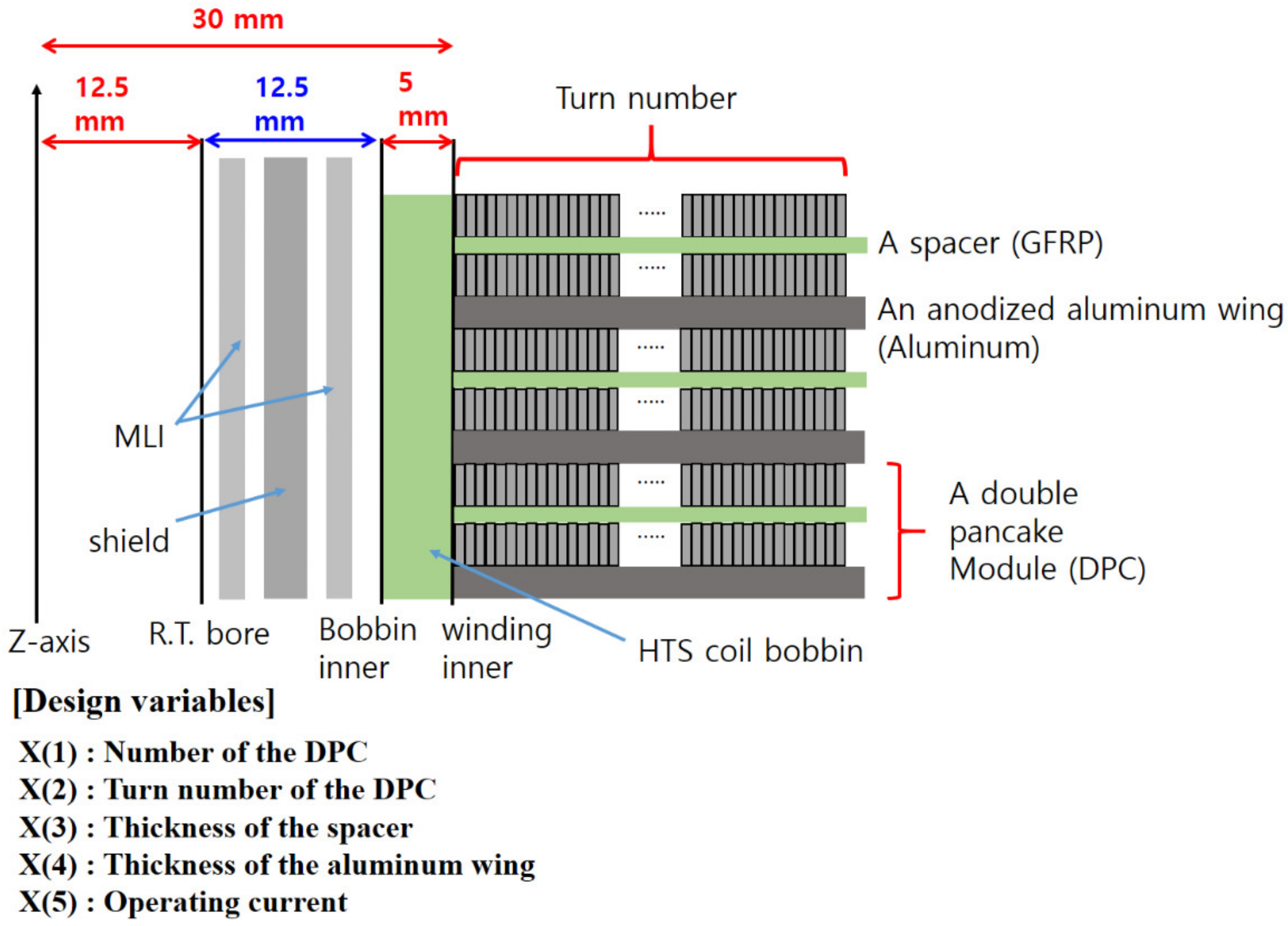
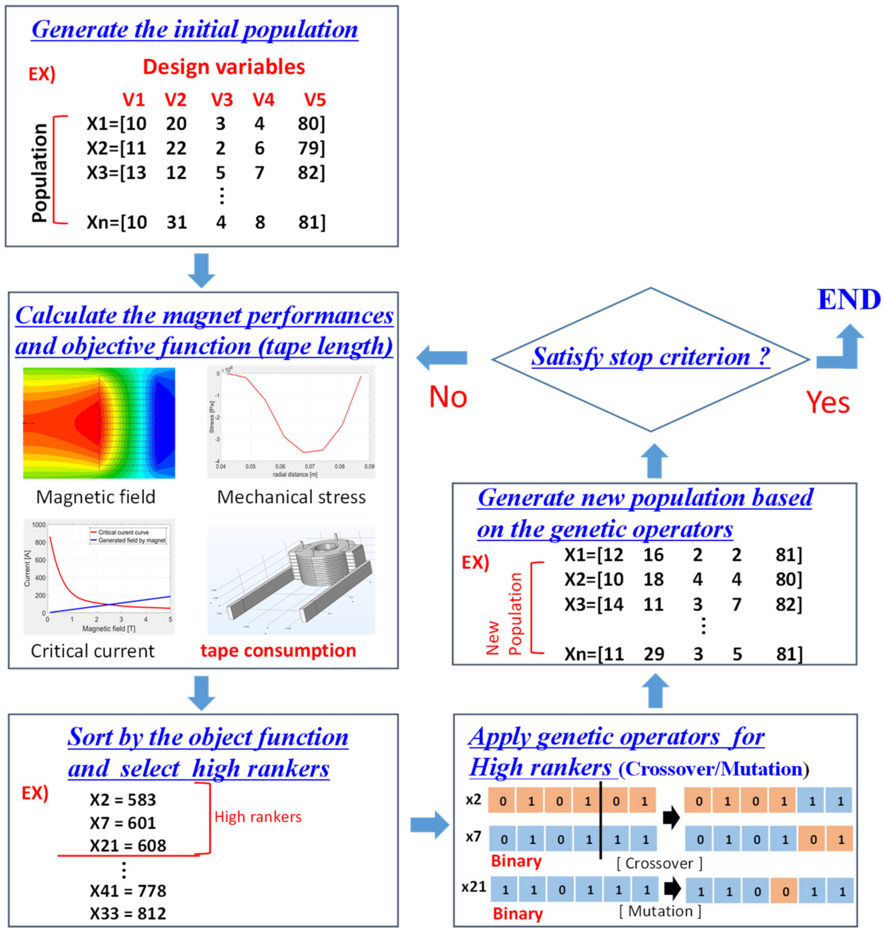
2. HTS Magnet Design with Genetic Algorithm
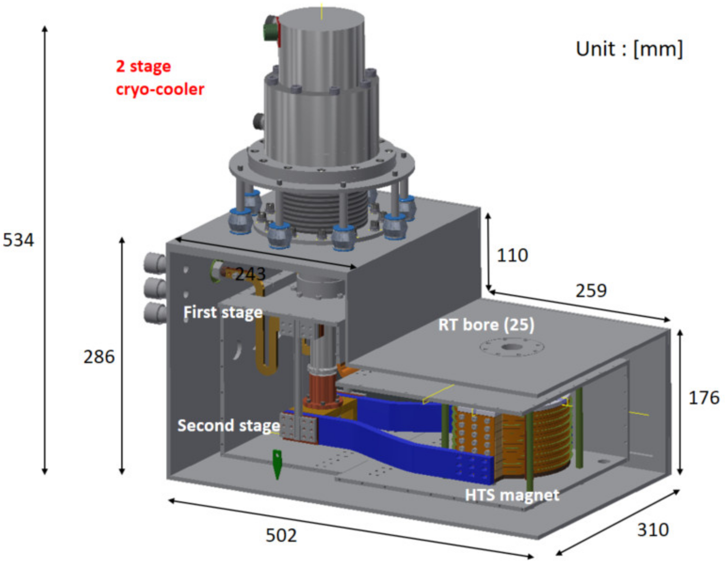
3. Magnet Construction
4. Magnet Operation
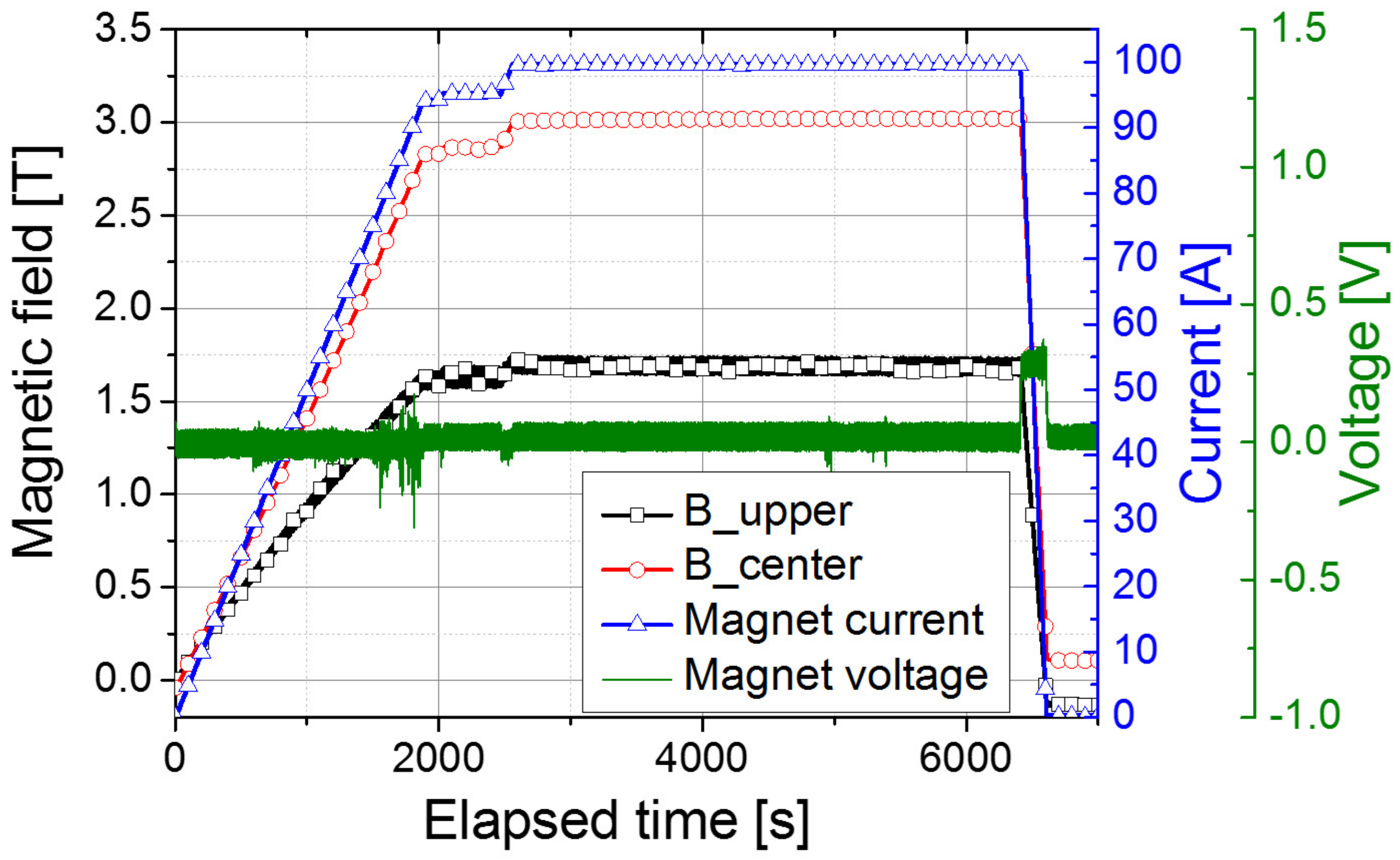
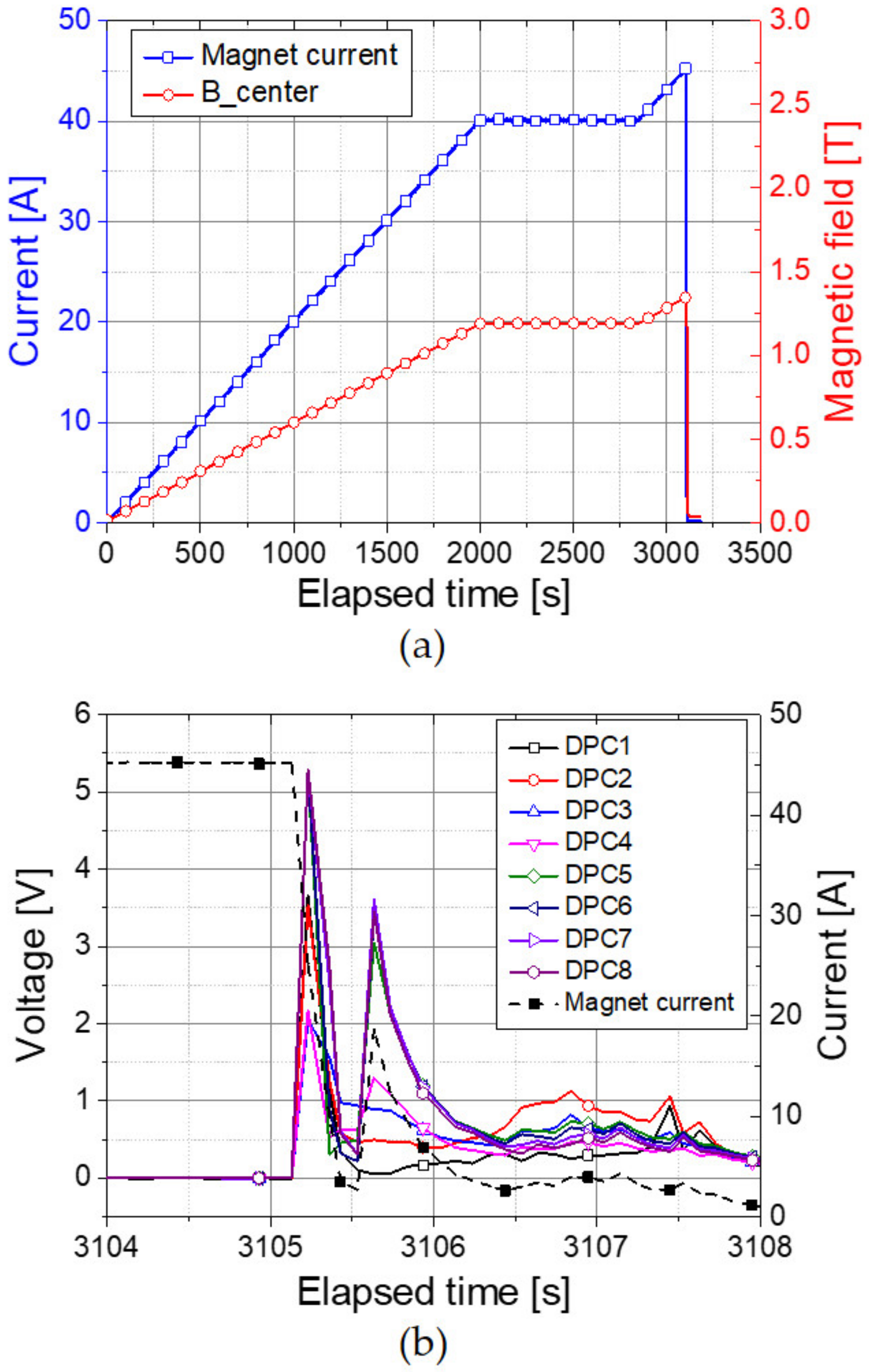
4.1. Charging Tests
4.2. Survival after a Sudden Discharge Due to a Magnet Power Supply Trip
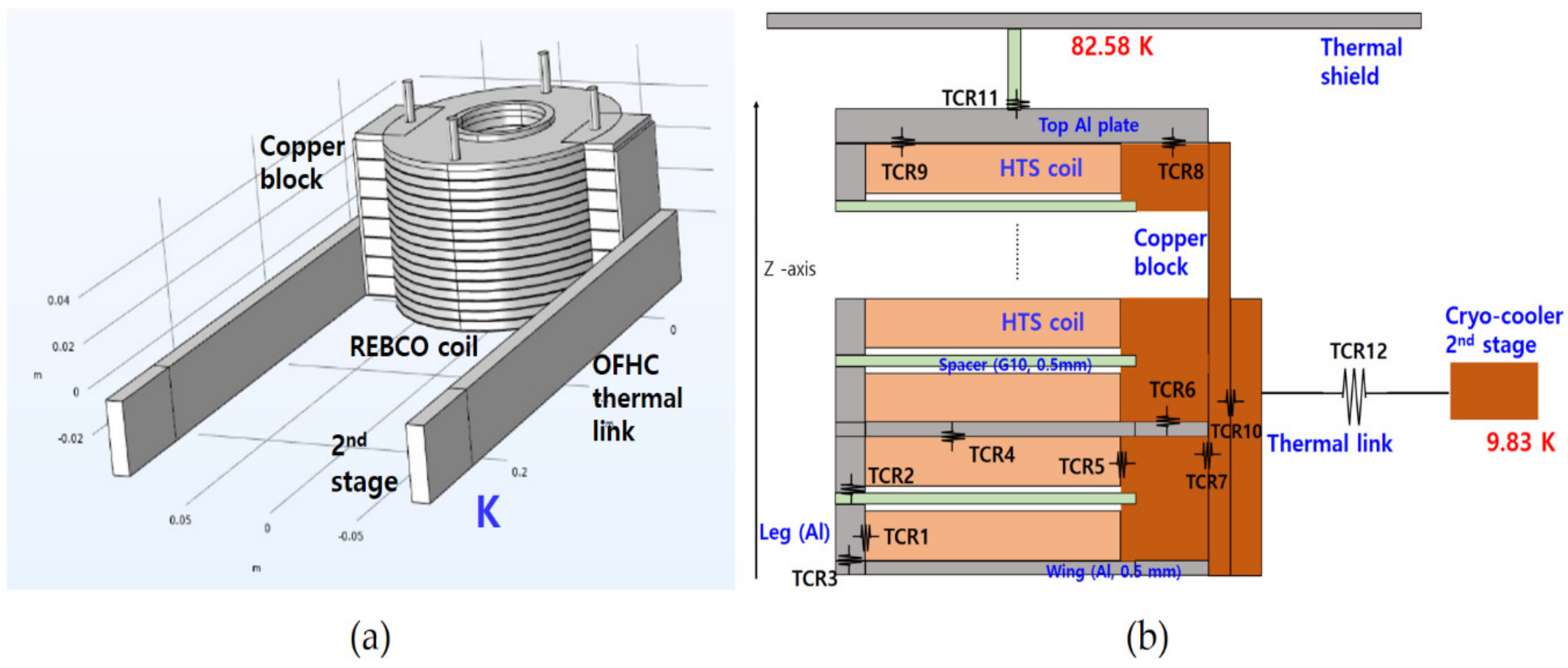
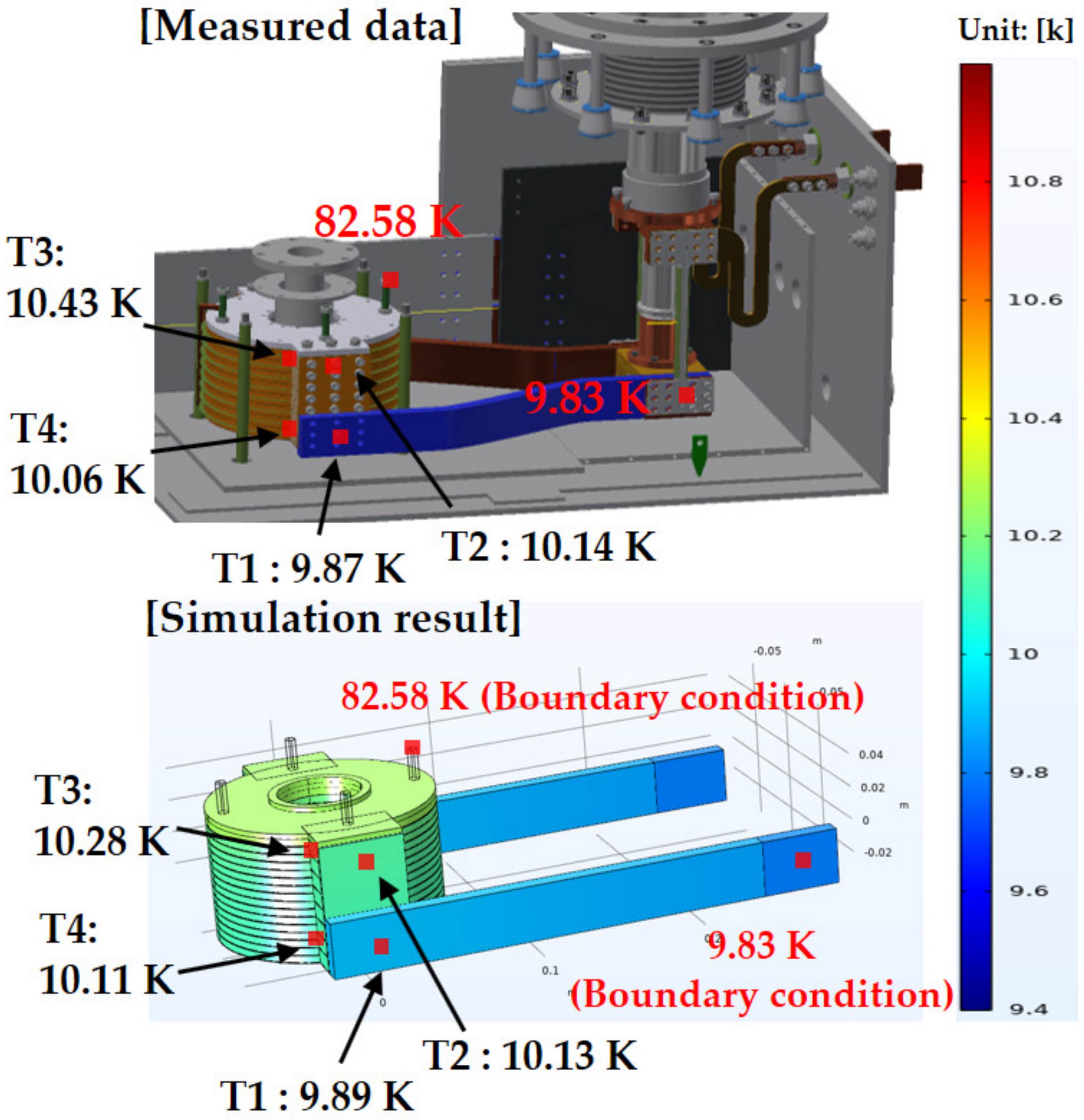
5. Thermal Analysis with the Finite Element Method (FEM)
6. Conclusions
Author Contributions
Funding
Institutional Review Board Statement
Informed Consent Statement
Data Availability Statement
Conflicts of Interest
References
- Parrell, J.A.; Zhang, Y.; Field, Y.; Cisek, P.; Hong, S. High field Nb/sub 3/Sn conductor development at Oxford Superconducting Technology. IEEE Trans. Appl. Supercond. 2003, 13, 3470–3473. [Google Scholar] [CrossRef]
- Maeda, H.; Yamazaki, T.; Nishiyama, Y.; Hamada, M.; Hashi, K.; Shimizu, T.; Suematsu, H.; Yanagisawa, Y. Development of Super-High-Field NMR Operated Beyond 1 GHz Using High-Temperature Superconducting Coils. eMagRes 2016, 5, 1109–1120. [Google Scholar]
- Schwalbe, H. New 1.2 GHz NMR Spectrometers—New horizons? Angew. Chem. Int. Ed. Engl. 2017, 56, 2–4. [Google Scholar] [CrossRef] [PubMed]
- Barth, C.; Komorowski, P.; Vonlanthen, P.; Herzog, R.; Tediosi, R.; Alessandrini, M.; Bonura, M.; Senatore, C. Generation of 25 T with an all-superconducting magnet system: Field profile and field quality measurements of a layer-wound 4 T REBCO insert coil for a 21 T LTS magnet. Supercond. Sci. Technol. 2019, 32, 075005. [Google Scholar] [CrossRef]
- Ma, W.; Hollis, T.; Viznichenko, R.; Twin, A.; Clarke, N.; Warren, D. Development of a 20 T 100 mm Cold Bore Superconducting Magnet System. J. Phys. Conf. Ser. 2020, 1559, 012120. [Google Scholar] [CrossRef]
- Wilson, W. Superconducting Magnets; Clarendon Press: Oxford, UK, 1987. [Google Scholar]
- Breschi, M.; Trevisani, L.; Bottura, L.; Derved, A.; Trillaud, F. Comparing the thermal stability of NbTi and Nb3Sn wires. Supercond. Sci. Technol. 2009, 22, 025019. [Google Scholar] [CrossRef]
- Iwasa, Y. Case Studies in Superconducting Magnets; Plenum Press: New York, NY, USA, 1994. [Google Scholar]
- Uglietti, D. A review of commercial high temperature superconducting materials for large magnets: From wires and tapes to cables and conductors. Supercond. Sci. Technol. 2019, 32, 053001. [Google Scholar] [CrossRef]
- Parkinson, B.J. Design considerations and experimental results for MRI systems using HTS magnets. Supercond. Scile. Technol. 2017, 30, 014009. [Google Scholar] [CrossRef]
- Kiyoshi, T.; Choi, S.; Matsumoto, S.; Zaitsu, K.; Hase, T.; Miyazaki, T.; Otsuka, A.; Yoshikawa, M.; Hamada, M.; Hosono, M.; et al. HTS-NMR: Present Status and Future Plan. IEEE Trans. Appl. Supercond. 2010, 20, 714–717. [Google Scholar] [CrossRef]
- Bascunan, J.; Hahn, S.; Park, D.K.; Iwasa, Y. A 2/4-GHz LTS/HTS NMR Magnet—A Progress Report. IEEE Trans. Appl. Supercond. 2011, 21, 2092–2095. [Google Scholar] [CrossRef]
- Bascunan, J.; Hahn, S.; Kim, Y.; Iwasa, Y. A New High-Temperature Superconducting (HTS) 700-MHz Insert Magnet for a 1.3-GHz LTS/HTS NMR Magnet. IEEE Trans. Appl. Supercond. 2013, 23, 4400304. [Google Scholar] [CrossRef] [PubMed]
- Iwasa, Y.; Bascunan, J.; Hahn, S.; Voccio, J.; Kim, Y.; Lecrevisse, T.; Song, J.; Kajikawa, K. A High-Resolution 1.3-GHz/54-mm LTS/HTS NMR Magnet. IEEE Trans. Appl. Supercond. 2015, 25, 4301205. [Google Scholar] [CrossRef] [PubMed]
- Piao, R.; Miyoshi, Y.; Yoshikawa, M.; Saito, K.; Hamada, M.; Matsumoto, S.; Suematsu, H.; Mochida, H.; Takao, T.; Suetomi, Y.; et al. Design and Development of a compact 1 GHz (23.5 T)-Class NMR Magnet with Bi-2223 Inner Coils. IEEE Trans. Appl. Supercond. 2019, 29, 4300407. [Google Scholar] [CrossRef]
- Kitaguchi, H.; Ozaki, S.; Miyazaki, T.; Ayai, N.; Sato, K.; Urayama, S.; Fukuyama, H. Development of a Bi-2223 HTS Magnet for 3 T MRI System for Human Brains. IEEE Trans. Appl. Supercond. 2010, 20, 710–713. [Google Scholar] [CrossRef]
- Slade, R.A.; Parkinson, J.; Walsh, R.M. Test Results for a 1.5 T MRI System Utilizing a Cryogen-free YBCO Magnet. IEEE Trans. Appl. Supercond. 2014, 24, 4400705. [Google Scholar] [CrossRef]
- Tosaka, T.; Miyazaki, H.; Iwai, S.; Otani, Y.; Takahashi, M.; Tasaki, K.; Nomura, S.; Kurusu, T.; Ueda, H.; Noguchi, S.; et al. R&D Project on HTS Magnets for Ultrahigh-Field MRI Systems. IEEE Trans. Appl. Supercond. 2016, 26, 4402505. [Google Scholar]
- Yokoyama, S.; Lee, J.; Imura, T.; Matsuda, T.; Eguchi, R.; Inoue, T.; Nagahiro, T.; Tanabe, H.; Sato, S.; Daikoku, A.; et al. Research and Development of the High Stable Magnetic Field ReBCO Coil System Fundamental Technology for MRI. IEEE Trans. Appl. Supercond. 2017, 27, 4400604. [Google Scholar] [CrossRef]
- Oya, M.; Matsuda, T.; Inoue, T.; Morita, T.; Eguchi, R.; Otake, S.; Nagahiro, T.; Tanabe, H.; Yokoyama, S.; Daikoku, A. Design and Manufacture of Half-size 3-T High-Temperature Superconducting Magnet for MRI. IEEE Trans. Appl. Supercond. 2018, 28, 4401205. [Google Scholar] [CrossRef]
- Bogdanov, I.V.; Kozub, S.S.; Sytnik, V.V.; Terskiy, I.S.; Tkachenko, L.M.; Trusov, O.V.; Shirshov, L.S.; Smirnov, V.M.; Shuvalov, V.I.; Shcherbakov, P.A.; et al. Design, fabrication and testing of a dipole magnet made with 2 G HTS wire. Supercond. Sci. Technol. 2016, 29, 105012. [Google Scholar] [CrossRef]
- John, J.H.; Badel, A.; Tixador, P. HTS Dipole Magnet for a Particle Accelerator Using a Twisted Stacked Cable. IEEE Trans. Appl. Supercond. 2016, 26, 4005205. [Google Scholar]
- Wang, X.; Abraimov, D.; Arbelaez, D.; Bogdanof, T.J.; Brouwer, L.; Caspi, S.; Dietderich, D.R.; Di Marco, J.; Francis, A.; Fajardo, L.G.; et al. Development and performance of a 2.9 Tesla dipole magnet using high-temperature superconducting CORC wires. Supercond. Sci. Technol. 2021, 34, 015012. [Google Scholar] [CrossRef]
- Rossi, L.; Senatore, C. HTS Accelerator Magnet and Conductor Development in Europe. Instruments 2021, 5, 8. [Google Scholar] [CrossRef]
- Kwon, Y.K.; Kim, H.M.; Baik, S.K.; Lee, E.Y.; Lee, J.D.; Kim, Y.C.; Lee, S.H.; Hong, J.P.; Jo, Y.S.; Ryu, K.S. Performance test of a 1 MW class HTS synchronous motor for industrial application. Phys. C 2008, 468, 2081–2086. [Google Scholar] [CrossRef]
- Sivasubramaniam, K.; Zhang, T.; Lokhandwalla, M.; Laskaris, E.T. Development of a High Speed HTS Generator for Airborne Applications. IEEE Trans. Appl. Supercond. 2009, 19, 1656–1661. [Google Scholar] [CrossRef]
- Nick, W.; Grundmann, J.; Frauenhofer, J. Test results from siemens low-speed, high-torque HTS machine and description of further steps towards commercialization of HTS machines. Phys. C 2012, 482, 105–110. [Google Scholar] [CrossRef]
- Herkert, M.O.; Bayer, D.; Kummeth, P.; Nick, W.; Arndt, T. Manufacturing and test of 2G-HTS coils for rotating machines: Challenges, conductor requirements, realizations. Phys. C 2012, 482, 111–118. [Google Scholar]
- Hahn, S.; Bascunan, J.; Kim, W.; Bobrov, E.S.; Lee, H.; Iwasa, Y. Field Mapping, NMR Lineshape, and Screening Currents Induced Field Analyses for Homogeneity Improvement in LTS/HTS NMR Magnets. IEEE Trans. Appl. Supercond. 2008, 18, 856–859. [Google Scholar] [CrossRef]
- Ahn, M.; Yagai, T.; Hahn, S.; Ando, R.; Bascunan, J.; Iwasa, Y. Spatial and Temporal Variations of a Screening Current Induced Magnetic Field in a Double-Pancake HTS Insert of an LTS/HTS NMR Magnet. IEEE Trans. Appl. Supercond. 2009, 19, 2269–2272. [Google Scholar]
- Koyama, Y.; Takao, T.; Yanagisawa, Y.; Nakagome, H.; Hamada, M.; Kiyoshi, T.; Takahashi, M.; Meda, H. Toward Beyond 1 GHz NMR: Mechanism of the Long-Term Drift of Screening Current-Induced Magnetic Field in a Bi-2223 Coil. Phys. C 2009, 469, 694–701. [Google Scholar] [CrossRef]
- Miyazoe, A.; Nakanishi, Y.; Sekino, M.; Kiyoshi, T.; Ohsaki, H. Magnetic Field Distribution Generated by Screening Current Flowing in Coated Conductor Arranged Edge-by-Edge and /or Face-to-Back. IEEE Trans. Appl. Supercond. 2012, 22, 4400504. [Google Scholar] [CrossRef]
- Jang, J.Y.; Hwang, Y.J.; Han, J.H.; Ahn, M.; Yang, H.; Hahn, S.; Bang, J.; Lee, S. Reproducibility of the field homogeneity of a metal-clad no-insulation all-REBCO magnet with a multi-layer ferromagnetic shim. Supercond. Sci. Technol. 2020, 33, 025005. [Google Scholar] [CrossRef]
- Sumitomo Cryogenic Group. CH-204 10K Cryocooler Series—SHI Cryogenics Group. Available online: http://www.shicryogenics.com/products/10k-cryocoolers/ch-204-10k-cryocooler-series (accessed on 25 February 2021).
- Coley, D.A. An Introduction to Genetic Algorithm for Scientists and engineers; World Scientific: Singapore, 1990. [Google Scholar]
- Cavaliere, V.; Formisano, A.; Martone, R.; Primizia, M. A genetic algorithm approach to the design of split coil magnets for MRI. IEEE Trans. Appl. Supercond. 2000, 10, 1376–1379. [Google Scholar] [CrossRef]
- Lecrevisse, T.; Iwasa, Y. A (RE)BCO Pancake Winding With Metal-as-Insulation. IEEE Trans. Appl. Supercond. 2016, 26, 4700405. [Google Scholar] [CrossRef]
- Sohn, M.; Sim, K.; Eom, B.; Ha, H.; Kim, H.; Seong, K. Controllability of the Contact Resistance of 2G HTS Coil With Metal Insulation. IEEE Trans. Appl. Supercond. 2018, 28, 4602705. [Google Scholar] [CrossRef]
- Song, J.; Chaud, X.; Borgnic, B.; Debray, F.; Fazilleau, P.; Lecrevisse, T. Construction and Test of a 7 T Metal-as-Insulation HTS Insert Under a 20 Thigh Background Magnetic Field at 4.2 K. IEEE Trans. Appl. Supercond. 2019, 29, 4601705. [Google Scholar] [CrossRef]
- Lee, J.; Lee, H.; Lee, J.; Choi, S.; Yoo, S.; Moon, S. RCE-DR, a novel process for coated conductor fabrication with high performance. Supercond. Sci. Technol. 2014, 27, 044018. [Google Scholar] [CrossRef]
- Hahn, S.; Kim, Y.; Park, D.K.; Kim, K.; Voccio, J.; Bascunan, J.; Iwasa, Y. No-insulation multi-width winding technique for high temperature superconducting magnet. Appl. Phys. Lett. 2013, 103, 173511. [Google Scholar] [CrossRef]
- Hahn, S.; Kim, Y.; Song, J.; Voccio, J.; Bascunan, J.; Iwas, Y. A-78mm/7-T Multi-Width No-Insulation ReBCO Magnet: Key Concept and Magnet Design. IEEE Trans. Appl. Supercond. 2014, 24, 4602705. [Google Scholar] [CrossRef]
- Kim, J.; Yoon, S.; Cheon, K.; Shin, K.H.; Hahn, S.; Kim, D.L.; Lee, S.; Lee, H.; Moon, S. Effect of Resistive Metal Cladding of HTS Tape on the Characteristic of No-Insulation Coil. IEEE Trans. Appl. Supercond. 2016, 26, 4601906. [Google Scholar] [CrossRef]
- Romeo, F.; Hoult, D.I. Magnet Field Profiling: Analysis and Correcting Coil Design. Magn. Reson. Med. 1984, 1, 44–65. [Google Scholar] [CrossRef]
- Li, F.X.; Voccio, J.; Ahn, M.; Hahn, S.; Bascunan, J.; Iwasa, Y. An analytical approach towards passive ferromagnetic shimming design for a high resolution NMR magnet. Supercond. Sci. Technol. 2015, 28, 075006. [Google Scholar] [CrossRef] [PubMed]
- Garret, M.W. Calculation of fields, forces and mutual inductance of current system by elliptic integrals. J. Appl. Phys. 1967, 38, 2538–2586. [Google Scholar] [CrossRef]
- Uglietti, D.; Seeber, B.; Abacherli, V.; Carter, W.L.; Flukiger, R. Critical currents versus applied strain for industrial Y-123 coated conductors at various temperatures and magnetic fields up to 19 T. Supercond. Sci. Technol. 2006, 19, 869–872. [Google Scholar] [CrossRef]
- Choi, S.; Kiyoshi, T.; Hahn, S.; Sugano, M. Stress Analysis of a High Temperature Superconductor Coil Wound With Bi-2223/Ag Tapes for High Field HTS/LTS NMR Magnet Application. IEEE Trans. Appl. Supercond. 2009, 19, 2237–2240. [Google Scholar] [CrossRef][Green Version]
- Montgomery, D.B. Solenoid Magnet Design; John Wiley & Sons Ltd.: Hoboken, NJ, USA, 1969. [Google Scholar]
- Markiewicz, W.D.; Vaghar, M.R.; Dixon, I.R.; Garmestani, H. Generalized Plane Strain Analysis of Solenoid Magnets. IEEE Trans. Appl. Supercond. 1994, 30, 2233–2236. [Google Scholar] [CrossRef]
- June, Y.; Yee, A.L.; Schwall, R.E. Thermal conductance of Cu/Cu and Cu/Si interfaces from 85 K to 300 K. Cryogenics 1992, 32, 610–615. [Google Scholar]
- Nishimo, K.; Yamashita, S.; Torii, K. Thermal contact conductance under low applied load in a vacuum environment. Exp. Thermal Fluid. Sci. 1995, 10, 258–271. [Google Scholar] [CrossRef]
- Song, J.; Hahn, S.; Lecrevisse, T.; Voccio, J.; Bascunan, J.; Iwasa, Y. Over-current quench test and self-protecting behavior of a 7 T/78 mm multi-width no-insulation REBCO magnet at 4.2 K. Supercond. Sci. Technol. 2015, 28, 114001. [Google Scholar] [CrossRef]
- Kim, K.; Kim, K.; Bhattarai, K.R.; Radcliff, K.; Jang, J.Y.; Hwang, Y.J.; Lee, S.; Yoon, S.; Hahn, S. Quench behavior of a no-insulation coil wound with stainless steel cladding REBCO tape at 4.2 K. Supercond. Sci. Technol. 2017, 30, 075001. [Google Scholar] [CrossRef]
- Jang, J.Y.; Yoon, S.; Hahn, S.; Hwang, Y.J.; Kim, J.; Shin, K.H.; Cheon, K.; Kim, K.; In, S.; Hong, Y.; et al. Design, construction and 13 K conduction-cooled operation of a 3 T 100 mm stainless steel cladding all-REBCO magnet. Supercond. Sci. Technol. 2017, 30, 105012. [Google Scholar] [CrossRef]
- Kim, M.S.; Choi, Y.S. Interfacial Contact Resistance Along the Thermal Link in Conduction-Cooled Low-Temperature Superconducting Magnet System. J. Supercond. Nov. Magn. 2014, 28, 681–684. [Google Scholar] [CrossRef]
- Ekin, J.W. Experimental Techniques for Low Temperature Measurements; Oxford University Press: Oxford, UK, 2006. [Google Scholar]


| Constraints | Value |
|---|---|
| Center field | >3 T |
| Field homogeneity @ 5 mm DSV * | <0.3% |
| Operating current | <60% of Ic* |
| Maximum hoop stress | <250 MPa |
| Magnet height | <80 mm |
| Outer radius | <70 mm |
| Design Variables | Results |
|---|---|
| X(1): Number of DPC * | 8 [EA] |
| X(2): Turn number of the DPC | 390 (195 × 2) [Turns] |
| X(3): Thickness of the spacer | 1.0 [mm] |
| X(4): Thickness of the aluminum wing | 1.0 [mm] |
| X(5): Operating current | 99 [A] |
| Parameters | results |
| Inductance | 0.55 [H] |
| Center field | 3.06 [T] |
| Field homogeneity | 0.233 [%] @ 5 mm DSV |
| Magnetic hoop stress | <14 [MPa] |
| Min. critical current | 163.5 [A] @ 20 K |
| Outer diameter | 138 [mm] |
| Height | 80.6 [mm] |
| Total length | 968.4 [m] |
| Index | Thermal Contact Resistance [K × m2/W] | Thermal Contact Materials |
|---|---|---|
| TCR1 | 1.3 × 10⁻³ | Copper/Aluminum |
| TCR2 | 1.11 × 10⁻⁴ | Aluminum/Aluminum |
| TCR3 | 1.11 × 10⁻⁴ | Aluminum/Aluminum |
| TCR4 | 1.3 × 10⁻³ | Copper/Aluminum |
| TCR5 | 50 | - |
| TCR6 | 1.3 × 10⁻³ | Copper/Aluminum |
| TCR7 | 1.7 × 10⁻⁴ | Indium/Copper |
| TCR8 | 1.3 × 10⁻³ | Copper/Aluminum |
| TCR9 | 1.3 × 10⁻³ | Copper/Aluminum |
| TCR10 | 3.33 × 10⁻³ | Copper/Copper |
| TCR11 | 1.11 × 10⁻⁴ | Aluminum/Aluminum |
| TCR12 | 1.7 × 10⁻⁴ | Indium/Copper |
Publisher’s Note: MDPI stays neutral with regard to jurisdictional claims in published maps and institutional affiliations. |
© 2021 by the authors. Licensee MDPI, Basel, Switzerland. This article is an open access article distributed under the terms and conditions of the Creative Commons Attribution (CC BY) license (https://creativecommons.org/licenses/by/4.0/).
Share and Cite
Jang, J.Y.; Kim, M.S.; Hwang, Y.J.; Song, S.; Choi, Y.; Choi, Y.S. Development of a Cryogen-Free Compact 3 T Superconducting Magnet for an Electromagnetic Property Measurement System. Appl. Sci. 2021, 11, 3074. https://doi.org/10.3390/app11073074
Jang JY, Kim MS, Hwang YJ, Song S, Choi Y, Choi YS. Development of a Cryogen-Free Compact 3 T Superconducting Magnet for an Electromagnetic Property Measurement System. Applied Sciences. 2021; 11(7):3074. https://doi.org/10.3390/app11073074
Chicago/Turabian StyleJang, Jae Young, Myung Su Kim, Young Jin Hwang, Seunghyun Song, Yojong Choi, and Yeon Suk Choi. 2021. "Development of a Cryogen-Free Compact 3 T Superconducting Magnet for an Electromagnetic Property Measurement System" Applied Sciences 11, no. 7: 3074. https://doi.org/10.3390/app11073074
APA StyleJang, J. Y., Kim, M. S., Hwang, Y. J., Song, S., Choi, Y., & Choi, Y. S. (2021). Development of a Cryogen-Free Compact 3 T Superconducting Magnet for an Electromagnetic Property Measurement System. Applied Sciences, 11(7), 3074. https://doi.org/10.3390/app11073074