Article

An MRI-Based Patient-Specific Computational Framework for the Calculation of Range of Motion of Total Hip Replacements

1
Biomechanics and Implant Technology Research Laboratory, Department of Orthopaedics, University Medicine Rostock, Doberaner Str. 142, 18057 Rostock, Germany
2
Aesculap AG Research and Development, 78532 Tuttlingen, Germany
3
Department of Orthopedic Surgery, University Hospital Carl Gustav Carus, Technische Universität Dresden, 01307 Dresden, Germany
*
Author to whom correspondence should be addressed.
Appl. Sci. 2021, 11(6), 2852; https://doi.org/10.3390/app11062852
Submission received: 24 February 2021 / Revised: 17 March 2021 / Accepted: 18 March 2021 / Published: 23 March 2021

Abstract

:
The calculation of range of motion (ROM) is a key factor during preoperative planning of total hip replacements (THR), to reduce the risk of impingement and dislocation of the artificial hip joint. To support the preoperative assessment of THR, a magnetic resonance imaging (MRI)-based computational framework was generated; this enabled the estimation of patient-specific ROM and type of impingement (bone-to-bone, implant-to-bone, and implant-to-implant) postoperatively, using a three-dimensional computer-aided design (CAD) to visualize typical clinical joint movements. Hence, patient-specific CAD models from 19 patients were generated from MRI scans and a conventional total hip system (Bicontact® hip stem and Plasmacup® SC acetabular cup with a ceramic-on-ceramic bearing) was implanted virtually. As a verification of the framework, the ROM was compared between preoperatively planned and the postoperatively reconstructed situations; this was derived based on postoperative radiographs (n = 6 patients) during different clinically relevant movements. The data analysis revealed there was no significant difference between preoperatively planned and postoperatively reconstructed ROM (∆ROM) of maximum flexion (∆ROM = 0°, p = 0.854) and internal rotation (∆ROM = 1.8°, p = 0.917). Contrarily, minor differences were observed for the ROM during maximum external rotation (∆ROM = 9°, p = 0.046). Impingement, of all three types, was in good agreement with the preoperatively planned and postoperatively reconstructed scenarios during all movements. The calculated ROM reached physiological levels during flexion and internal rotation movement; however, it exceeded physiological levels during external rotation. Patients, where implant-to-implant impingement was detected, reached higher ROMs than patients with bone-to-bone impingement. The proposed framework provides the capability to predict postoperative ROM of THRs.

1. Introduction

Total hip replacement (THR) constitutes the gold standard for the treatment of end-stage hip osteoarthritis and is currently performed more than 230,000 times per year in Germany [1,2]. In 2015, the incidence of THR surgery was 166 per 100,000 cases in the OECD34 region [3]. This number is expected to rise [4,5,6] due to an increase in life expectancy of a globally aging population [5,7]. In this context, complications after THR represent an economic burden for the world healthcare system, which is primarily owing to an increasing number of primary and revision operations [5].
Despite improvements in surgical techniques and implant designs, impingement and dislocation constitute a crucial cause of failure of THR; this is due to a limited postoperative range of motion (ROM) during activities of daily living [7,8]. Besides aseptic loosening, dislocation is one of the major complications of hip replacement [1,9,10,11]. In the USA, dislocation is considered as the most common indication for revision surgery [8]. A high ROM is essential, especially for patients with extreme movements in different populations worldwide as well as for young and more active patients [9,10]. Besides bone and prosthetic impingement, the ROM of THRs may also be limited due to the surrounding soft-tissue structures [11]. The impingement process and, thus, the resulting ROM are dependent on patient-specific anatomy, the implant design, and intraoperative implant position, as well as the condition of the surrounding patient-specific soft-tissue structures [12,13,14,15,16,17,18,19,20]. Additionally, impingement can cause hip joint instability, induce wear or damage to the articulating implant surfaces, reduce the implant fixation, and cause total hip dislocation [16,21,22]. Moreover, impingement of the femoral neck on the acetabular cup can result in increased wear and liner damage due to higher contact pressure at the contact point, presenting a higher risk for subluxation or dislocation [21]. Hereby, impingement is responsible for the lever arm to lever out the prosthetic head from the acetabular cup.
Currently, the occurrence of impingement is manually assessed by an orthopedic surgeon, by intraoperatively imposing specific motion patterns while the impingement is detected [23]. To analyze the maximum ROM of different implant designs, several experimental [24,25,26,27,28,29] and computational studies [13,18,20,21,23,30,31,32,33,34,35,36,37,38], using computer-aided design (CAD), finite element analyses, or multibody simulations, have been conducted. Previous studies described the effect of the orientation of the acetabular cup, prosthetic head size on the impingement, and risk of dislocation [21,39,40]. A recent computational study conducted by Widmer et al. [41] optimized the recommendations to reach the largest impingement-free ROM, by finding optimal target zones for implant positioning; this was achieved by using 3D kinematic hip motion analyses with respect to the contribution of various intraoperative positioning and implant design parameters. In a retrospective study, the sagittal orientation of the pelvis after THR was investigated, which is an important factor for functional cup orientation [42]. However, most of the studies did not consider real patient-specific data or were mostly based on computed tomography (CT) scans, which were hazardous for the patient, and, therefore, not the first choice in a preoperative planning scenario. The ROM is linked to the postoperative outcome and has attracted attention from the research community by using experimental and numerical methods [21,30,38,41,43,44,45,46,47,48,49,50,51,52]. Despite these studies, there is, to our knowledge, no approach that can be used to assess ROM in preoperative planning without subjecting the patient to additional radiation by CT scanning. In this regard, due to the high anatomical variability of hip joint geometry, patient-specific geometries are needed to perform more realistic computational preoperative analysis [23,32].
We aimed to prove the feasibility of investigating ROM, based on patient data, using the proposed methodology which enables the computational prediction of postoperative ROM, depending on the component selection and alignment. Therefore, we introduce a magnetic resonance imaging (MRI)–based computational framework to support the preoperative assessment of THRs. In this context, MRI allows computational reconstruction of the bone structures, enabling the virtual implantation of different endoprosthetic designs and various implant positioning. Moreover, this ensures that patients undergoing a computational assessment of ROM using the proposed methodology are not exposed to additional amounts of radiation. The framework will be subjected to verification steps, to enable the estimation of the patient-specific ROM and type of impingement (bone-to-bone, implant-to-bone, and implant-to-implant) postoperatively by using three-dimensional CAD, which will visualize typical clinical movement maneuvers. Hence, we generated patient-specific CAD models from THR patients from MRI scans (n = 19) and calculated the ROM of a virtually implanted and commercially available THR system for this patient cohort. Additionally, the ROM was compared between the preoperatively planned and the postoperatively reconstructed situation; the latter was derived from postoperative radiographs. Finally, we used the proposed framework to evaluate the effect of different implant-specific parameters (size of the prosthetic head and acetabular cup) on the estimated postoperative ROM of the patients.

2. Materials and Methods

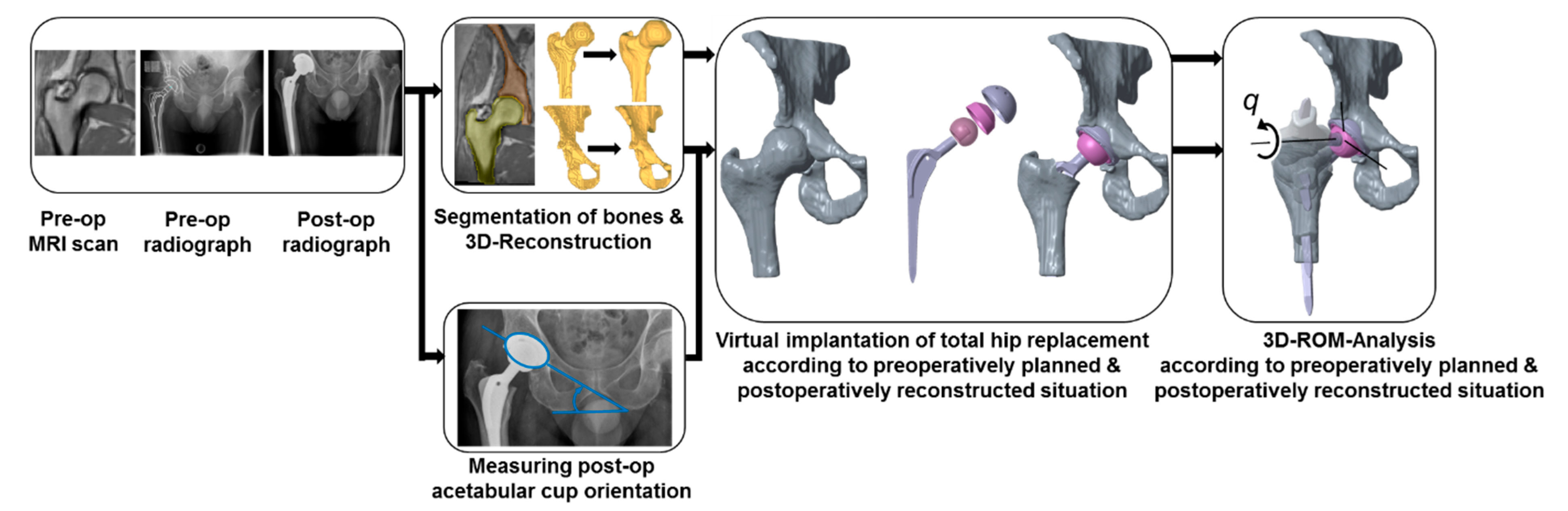
2.1. Overview of the Deployed Framework

In this study, we introduce a new computational framework (Figure 1), which is based on non-invasive MRI data of patients, and a previously described method of CAD modeling [18,24,30,53]; this enables the estimation of the patient-specific ROM for THRs during the movements similar to ISO-21535 and clinical joint movements [54,55,56,57].
On the one hand, the implant component alignment was derived from the preoperatively planned situation. On the other hand, the alignment was derived from the postoperatively reconstructed situation, enabling comparison between both situations. In this context, 19 patients (8 females and 11 males) suffering from hip osteoarthritis and scheduled for THR (Universitätsklinikum, Dresden, Germany) were selected to investigate the ROM of the artificial joint after virtual implantation of a THR (Figure 1). The mean age of the 19 patients was 52.1 ± 7.2 years. More precisely, six of these patients received surgical treatment with a Bicontact hip stem system (Aesculap AG, Tuttlingen, Germany), where the implant component alignment was virtually reconstructed using postoperative radiographs by the method of Liaw et al. [58]. The Bicontact hip stem (size from 10 to 16), with different centrum–collum–diaphyseal (CCD) angles (128° and 135°), was combined with a ceramic ball head (diameter 28 to 36 mm, cone 12/14 mm) consisting of BIOLOX®delta (CeramTec, Plochingen, Germany). Furthermore, the acetabular cup (outer diameter 46 to 60 mm, Plasmacup® SC) (Aesculap AG, Tuttlingen, Germany) was equipped with the Plasmacup® delta ceramic liner (BIOLOX®delta, inner diameter 28 to 36 mm). All the patient cases with the implant-specific parameters are presented in Table 1. Note that intraoperative deviations from preoperative planning have occurred and, therefore, some patients have been treated with different implant component sizes. Regarding the THR design, different implant-specific design parameters for the examined THR are depicted in Figure 2.

2.2. Geometry Data Acquisition

For each patient, preoperative MRI scans of the native hip joint (hi-res, voxel-size 1.8 mm) and an overview MRI of the distal femur and the pelvis were conducted. Additionally, standard pre- and postoperative radiographs (anterior–posterior projection) of the hip joint treated with THR were acquired. The study was approved by the local ethics committee (EK 175052011). Written informed consent was obtained from all patients before participation.
The MRI files of the patients were imported in the software package Amira (v.5.4.1, Zuse Institute Berlin, Berlin, Germany; Thermo Fisher Scientific, Waltham, MA, USA), to reconstruct the 3D bone surface models using triangulated surfaces. The 3D surface models of the bony structure of the femur and acetabulum were obtained (Figure 1) by manually segmenting the bony structures slice per slice. Subsequently, the resulting 3D surface models were smoothed and converted into surfaces of mathematically defined non-uniform rational B-splines (NURBS) using Geomagic Studio (v.2013, 3D Systems, Rock Hill, SC, USA) [59]. In this manner, we enabled the subsequent virtual implantation of THR implants.
Accordingly, an established joint coordinate system of the pelvis was generated according to Kluess et al. [18]. The pelvic coordinate system was created, originating out of the center of rotation of the hip joint, by fitting a sphere into the articulating joint surface of the acetabulum and defining its orientation using anatomical landmarks. The x-axis connected the right and left spinae iliacae anterior superior; the z-axis touched the pubic symphysis and was directed cranially. Consequently, the y-axis was defined perpendicular to the x- and z-axis. The axes were translated into the center of rotation, and the Cartesian coordinate system, which refers to the anterior pelvic plane, was set up. In anatomical terms, this means that the x-axis represents the medio-lateral direction; the y-axis, the anterior–posterior direction; and the z-axis, the inferior–superior direction.
The femoral coordinate system was generated using the anatomical frontal, sagittal, and transversal planes, which were defined by anatomical landmarks [18]. The frontal plane was defined as being tangential to three points: the most posterior points of the medial and lateral femoral condyles, and the most posterior point of the trochanter minor. The sagittal plane was perpendicular to the frontal plane and contained the most lateral points of the condylus lateralis and trochanter major. Additionally, the transversal plane was perpendicular to the frontal and sagittal plane and contained the most distal point of the femoral condyles. Additionally, the condylar notch was marked to allow reconstruction of the mechanical axis after virtual implantation. The defined planes were transformed into the center of rotation of the hip joint, which was defined using a spherical best-fit algorithm at the femoral head and acetabulum.
The virtual implantation of the THR and the ROM analyses were conducted with the CAD software Creo Parametric (v.2.0, Parametric Technology Corporation, Boston, MA, USA) according to the preoperatively planned and postoperatively reconstructed situation, where the components were aligned under the supervision of one experienced orthopedic surgeon using clinical imaging data.

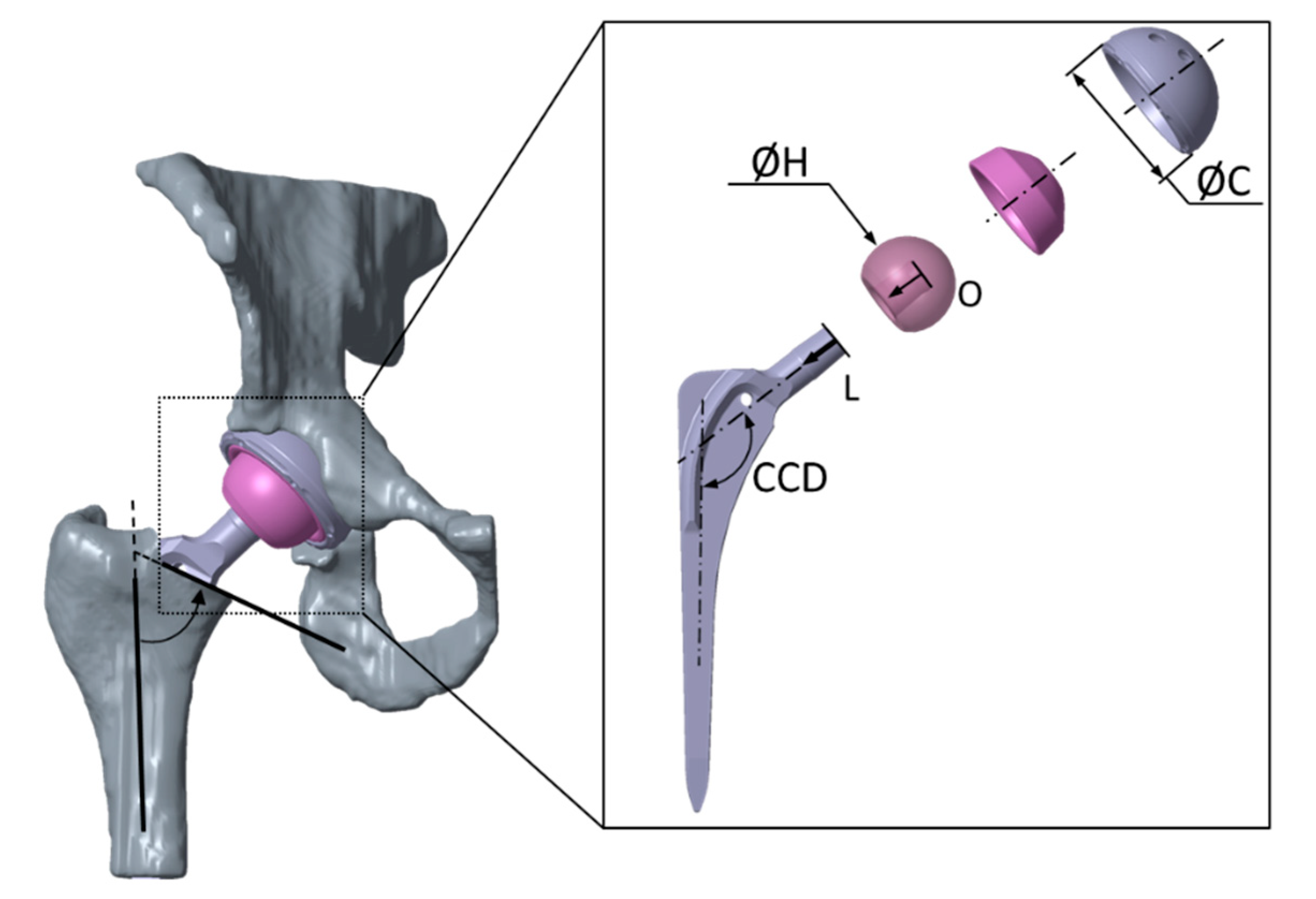
2.3. Preoperatively Planned Situation

To represent the ideal configuration of the THR, implants were positioned according to the surgical technique of the manufacturer and preoperative planning. Prior to the placement of the femoral hip stem, virtual resection of the femoral head was performed using Boolean operations, resembling the principle of step osteotomy and an osteotomy plane angle of 55° relative to the femoral shaft axis (Figure 2). After virtual osteotomy, the hip stem equipped with the prosthetic head was aligned parallel to the shaft axis of the proximal femoral bone. The placement of both the THR components aimed for the best possible restoration of the preoperative center of rotation of the hip joint. Furthermore, the prosthetic shaft was well centered in the medullary femoral canal. Finally, the acetabular cup was aligned with 45° of inclination and 15° anteversion referenced to the anterior pelvic plane.

2.4. Postoperatively Reconstructed Situation

The postoperative situation of the THR was reconstructed by virtual implantation based on postoperative radiographs of the hip joint. Due to metallic artifacts in the postoperative MRI data, the preoperative MRI scans were also used for virtual implantation. In particular, the postoperative acetabular cup position was derived from two-dimensional anterior–posterior radiographs of six patients who received the Bicontact hip system (Table 1). The definitions for radiological inclination and anteversion were adopted from Murray et al. [60]. Therefore, radiologic inclination angle α was derived from the postoperative radiograph, measuring the angle between a line defined by the lowest points of both ischiadic bones and a line defined by the two edges of the acetabular cup. The anteversion angle β was determined according to Liaw et al. [58], where α is the inclination angle, μ is the correction angle, S is the short axis of the ellipse, and L is the long axis of the ellipse, which is derived from the projection circular opening of the acetabular cup in the two-dimensional radiograph.
  β   =   tan 1 ( tan ( tan 1 ( tan ( sin 1 ( S L ) ) ( 1 sin ( α ) ) ) +   μ ) sin ( α ) )
The correction angle µ reduces the error due to the perspective projection. It was determined with the following equations using anatomical landmarks [61]:
µ   =   tan - 1 ( ( x 2 + Δ x ) / z )
z   =   x 2 / tan 5 . 46 °
where Δx represents the distance between the symphysis pubis and a perpendicular line in the middle of the radiograph, x is the distance between the left and right acetabular center of rotation, and z is the distance of the radiation source from the image plane [61].
Similarly, the virtual implantation of the THR was conducted analogously to the procedure during the configuration, according to the preoperatively planned situation. The acetabular cup was aligned using the inclination and anteversion angles derived previously from the anterior–posterior radiographs, and the femoral stem was implanted using postoperative radiographs for deriving the alignment. The antetorsion of the native femur and the virtually implanted femoral hip stem was determined according to the method of Dunlap et al. [62]. First, the transepicondylar axis on the distal femur of each case was determined using the Amira software (v.5.4.1, Zuse Institute Berlin, Berlin, Germany; Thermo Fisher Scientific, Waltham, MA, USA). The transepicondylar axis, femoral neck axis, and implant neck axis were projected to the horizontal plane perpendicular to the femoral shaft axis for each case. Based on the horizontal plane, the anteversion of the virtually implanted hip stems was determined. The final positions of the implant components after virtual implantation, according to the data described above, were verified for each case by an experienced orthopedic surgeon.

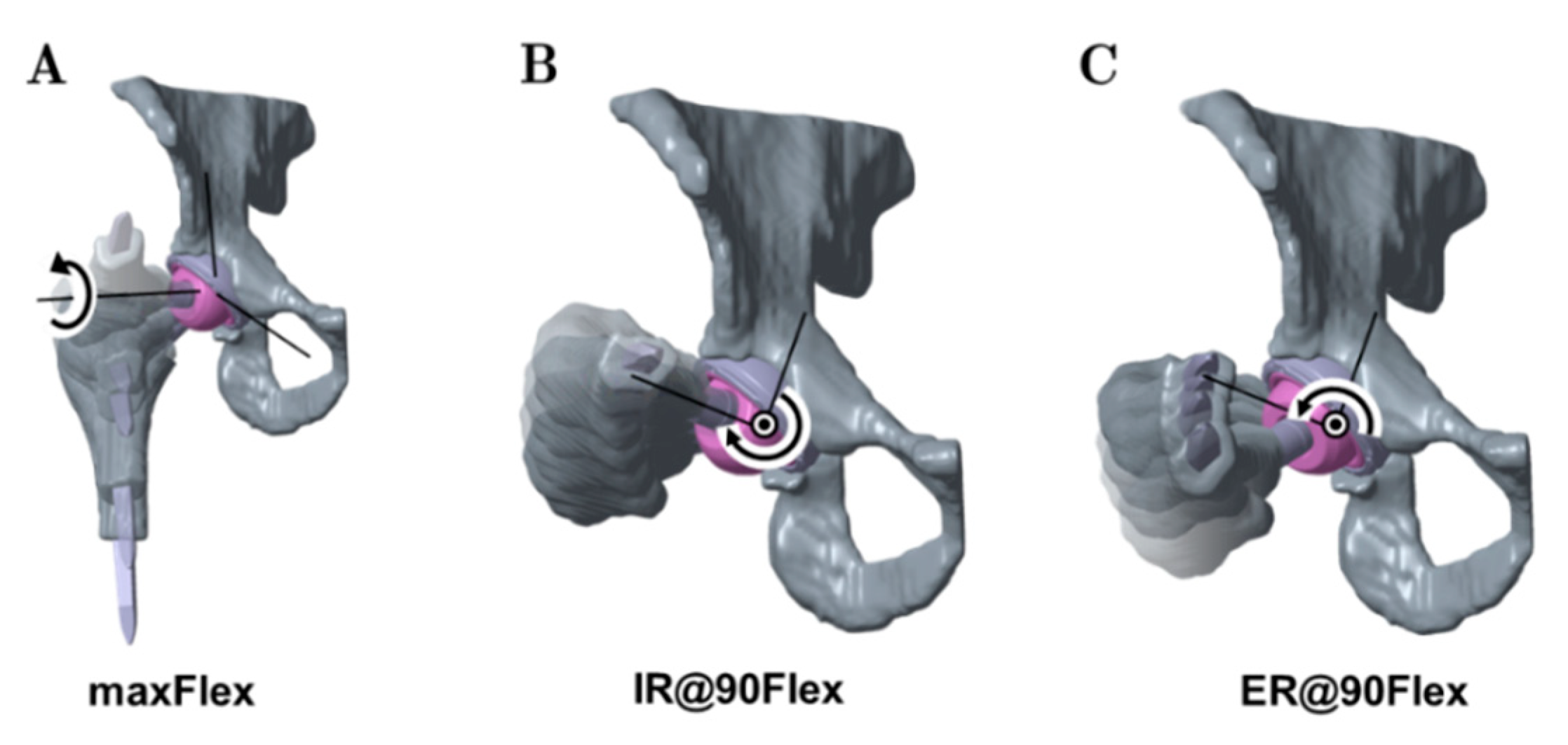
2.5. Analysis of Range of Motion

The ROM analysis was conducted with Creo Parametric (v.2.0, Parametric Technology Corporation, Boston, MA, USA) by deploying a kinematic motion analysis, using a kinematic chain. In this manner, a predefined motion until impingement was applied to the hip joint. The coordinate systems of the femur and acetabulum, respectively, were translated to the center of rotation of the virtually implanted acetabular cup and into the center of rotation of the virtually implanted femoral head. Subsequently, the initial positioning of the pelvic bone and the femur to each other was performed according to the anatomical positional relationships. The collision detection routine of Creo Parametric was considered to detect the occurrence of impingement situations [18]. For this, the contact was defined between the external surfaces of the femur and the pelvis, between the femoral hip stem and the acetabular cup, and between the femoral hip stem and the liner. The motion was stopped when a collision between bone and bone, implant and bone, or implant and implant was detected.
The rigid bodies of bones and implant components were connected by ideal joints to set up a kinematic chain. The acetabulum was assumed to be ground fixed, followed by the acetabular cup and liner, which were also fixed to the pelvic bone. The prosthetic head, together with the hip stem, was fixed to the femoral bone and these were connected to the acetabular cup and liner fixed to the pelvic bone by a spherical joint, with a fixed center of rotation. The kinematic chain represents an open-loop mechanism. A virtual servomotor with a constant angular velocity was used to impose a specific motion in one degree of freedom between the two bodies along a predefined fixed rotational axis of the joint.
Generally, the motion was started at the initial configuration for each load case and continued until impingement [23,63] was detected. In our approach, impingement between femoral configuration—consisting of the femoral bone, stem, and prosthetic head—and pelvic configuration—consisting of the pelvic bone, acetabular cup, and liner—was recognized. The definition of contact in this algorithm is the occurrence of the intersection between pelvic and femoral configuration. The hip joint angle at this specific position was then recorded as the functional ROM of the THR. Within the ROM analysis, three different movements similar to ISO-21535 and typical clinical joint movements [54,55,56,57] were considered (Figure 3): maximum flexion from neutral (maxFlex), combined internal rotation at 90° flexion (IR@90Flex), and combined external rotation at 90° flexion (ER@90Flex).
The neutral position of the hip joint for the maxFlex movement is defined by bringing the sagittal plane and transversal plane of the pelvis into coincidence with the sagittal plane and transversal plane of the femur. The flexion axis is defined by the intersection of the transversal and frontal plane. A flexion rotation was applied until impingement was detected.
For IR@90Flex and ER@90Flex, the mechanical axis of the femur, which is defined by the condylar notch and the center of rotation of the femoral head, was used as a femoral rotational axis. The initial configurations of these motions were generated by applying 90° of flexion, using the neutral position of the maxFlex motion. Subsequently, internal rotation or external rotation started and was performed until impingement was detected.
Finally, the resulting ROM and type of impingement (bone-to-bone, implant-to-implant, and implant-to-bone) were analyzed during the three movements.

2.6. Analyzed Parameters

Within the framework of the study, the results for the preoperatively planned situation were compared with the postoperatively reconstructed situation for the n = 6 patients (13 patients had to be excluded due to different treatment options with other THR designs), who received the Bicontact total hip replacement system as planned. The mean ROM and the achieved ROM, depending on the type of impingement, were evaluated during flexion, internal rotation, and external rotation. Moreover, the quantity for each of the three impingement types was also evaluated.
The influence of the design-specific parameters of the Bicontact implant system for n = 9 patients on the resulting ROM was investigated in terms of the CCD angle, acetabular cup size, prosthetic head size, and head offset. These implant configurations were derived from a preoperative surgery planning tool by an orthopedic surgeon.

2.7. Statistical Metrics

All data given in the diagrams are expressed as mean values ± standard deviation (SD). The deviation in ROM (∆ROM) between the postoperatively reconstructed and preoperatively planned situation was calculated using the median of differences. Statistical analyses were performed using SPSS V27.0 (SPSS® Inc., Chicago, IL, USA), to determine statistically significant differences in the ROM of the preoperatively planned situation and postoperatively reconstructed situation for each of the three movements. Both situation groups within the movements, maxFlex, IR@90Flex, and ER@90Flex, were examined for statistically significant differences with the Wilcoxon test. The preoperatively planned situation and postoperatively reconstructed situation of the same patient were assumed to be combined samples. A level of p ≤ 0.05 was considered statistically significant.

3. Results

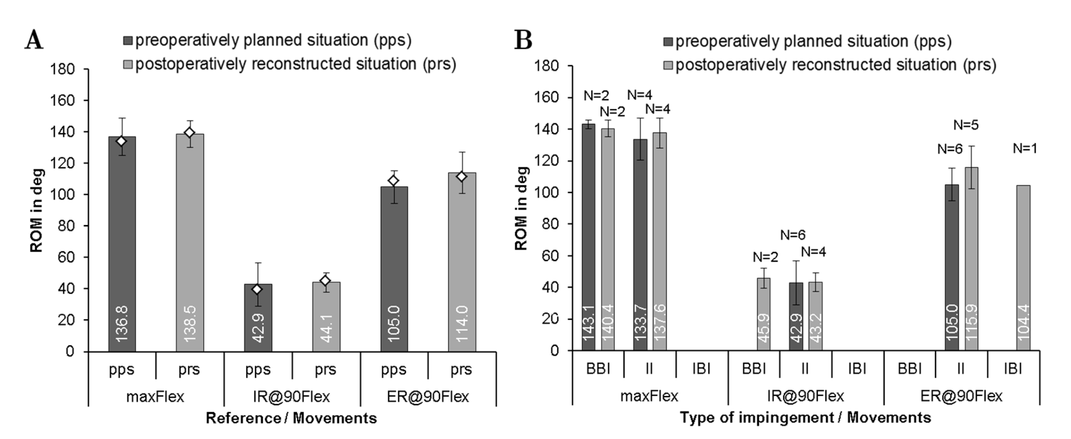
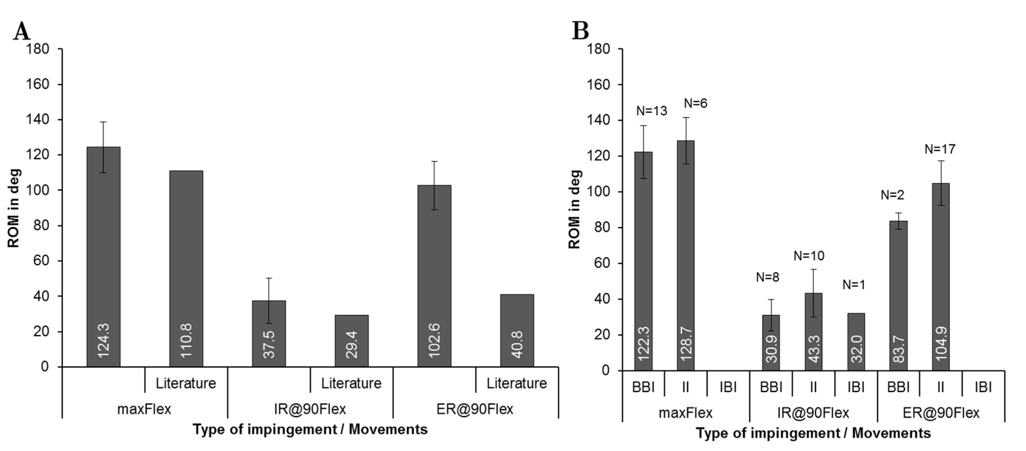
3.1. Comparison of ROM and Predominant Impingement Type between the Preoperatively Planned and Postoperatively Reconstructed Situation

The maximum ROM until impingement was evaluated for all patients according to the preoperatively planned and postoperatively reconstructed situation. Concerning the postoperatively reconstructed situation, n = 6 patients were compared with the respective preoperatively planned situation (Figure 4).
The mean femoral stem antetorsion was 6.9° ± 9.1° for preoperatively planned situation and 4.5° ± 4.6° for the postoperatively reconstructed situation. Regarding the acetabular component, the cup was implanted with 45° inclination and 15° anteversion for the preoperatively planned situation and 39.7° ± 4.7° inclination and 22.9° ± 6.6° anteversion for the postoperatively reconstructed situation. The ROM analysis (Figure 4A) showed no significant difference between both groups for flexion (∆ROM = 0°, p = 0.854) and internal rotation movement (∆ROM = 1.8°, p = 0.917). Contrarily, a significant difference was detected during external rotation (∆ROM = 9°, p = 0.046). Regarding the impingement, the postoperatively reconstructed situation showed a shift to more implant-to-implant impingement for internal rotation. During flexion and external rotation, larger angles up to the implant-to-implant impingement were determined in the analysis of the postoperatively reconstructed situation (Figure 4B). In the case of bone-to-bone impingement, the flexion angles of 143.1 ± 2.7° and 140.4 ± 5.4° were determined in the preoperatively planned and postoperatively reconstructed situation, respectively.

3.2. Investigation of ROM and Predominant Impingement Type for the Preoperatively Planned Situation

The femoral stem antetorsion, which included n = 19 patients, preoperatively ranged from 0.4° to 40°. The comparison of the ROM for the three motions is depicted in Figure 5A. After virtual implantation, 124.3° ± 14.5° of mean flexion was reached. Internal rotation averaged at 37.5° ± 12.9° and external rotation at 102.6° ± 13.6°. Compared to physiological ROMs [18,64], similar values were observed for flexion and internal rotation. Contrarily, the ROM for external rotation of the patients treated with THR exceeded the physiological ROM [54]. Within the ROM analysis, the different types of impingement at maximum ROM was detected depending on the movement (Figure 5B). Regarding the type of impingement, a maximum flexion of 128.7 ± 13.0° up to the implant impingement was detected. In the case of bone-to-bone impingement, the ROM slightly decreased to 122.3° ± 14.7°. The predominant type of impingement at the flexion movement (Figure 5B) was bone-to-bone impingement with N = 13, followed by implant-to-implant impingement with N = 6, while for internal rotation, implant-to-implant impingement with N = 10 was followed by bone-to-bone impingement with N = 8. Implant-to-implant impingement was the most dominant type of impingement during external rotation, which occurred in 17 out of 19 patients. It is apparent (Figure 5B) that bone impingement restricted the ROM more than implant impingement during all movements. It is also noteworthy that implant-to-bone impingement occurred only once in all 19 patients.

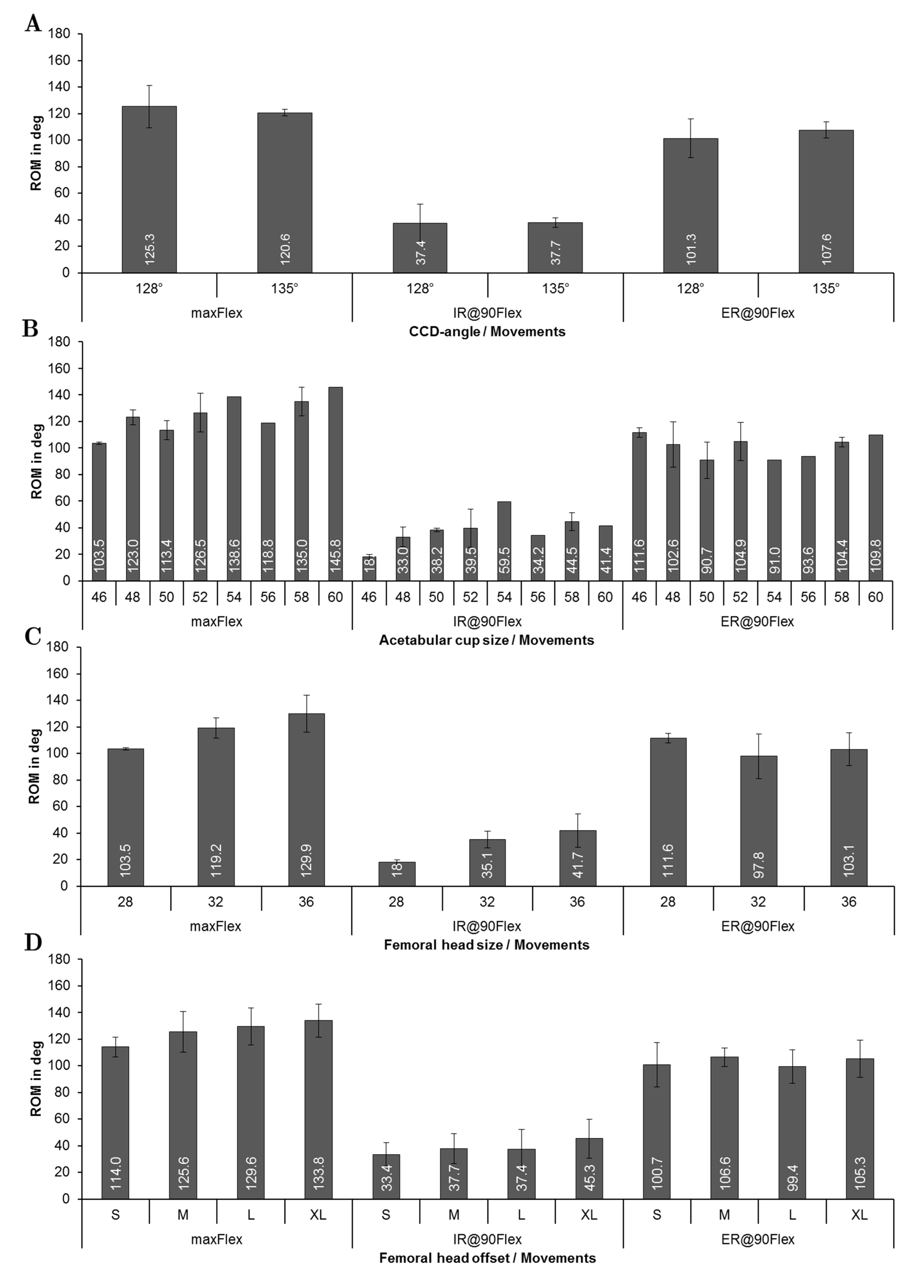
3.3. Influence of Implant Related Factors on ROM for the Preoperatively Planned Situation

Figure 6 gives an overview of the ROM concerning the implant-specific design parameters–stem size, CCD-angle, acetabular cup size, prosthetic head size, and femoral neck length for the preoperatively planned situation (n = 19 patients). The results in relation to CCD-angle (Figure 6A) showed that there was a minor decrease in ROM using a higher CCD-angle during flexion (125.3 ± 16.1° for 128° CCD-angle and 120.6 ± 2.5° for 135° CCD-angle). Contrarily, the ROM was slightly higher when CCD-angle was increased (101.3° ± 14.7° for 128° CCD-angle and 107.6 ± 6.0° for 135° CCD-angle) during external rotation.
It was observed that as the acetabular cup size was increased, progressively more ROM during flexion was achieved (Figure 6B). For instance, impingement occurred at 103.5° ± 0.9° during flexion in case of a 46 mm cup, while impingement occurred at 145.8° of flexion in case of a 60 mm cup. A larger cup was also related to a higher maximum internal rotation at 90° of flexion (increased by up to 130%), whereas no clear trend was observed during external rotation. Figure 6C depicts the ROM depending on the head size, where each patient received a femoral stem equipped with a taper 12/14, which establishes the connection between stem and head. Every stem had, therefore, the same neck diameter, which links the prosthetic head size directly to the head-to-neck ratio. For this patient group, the head-to-neck ratio ranged from 2.07 for a 28 mm head to 2.67 for a 36 mm head (reported in Table 1 for all patients). The ROM until impingement increased with increasing head size. Accordingly, the head size of 28 mm resulted in 103.5° ± 0.9° and a head size of 36 mm resulted in 129.9° ± 13.9° during flexion. During internal rotation, the ROM rose from 18° ± 1.8° (28 mm head size) to 41.7° ± 12.7° (36 mm head size). A higher head offset (Figure 6D), which was defined by the design of the prosthetic head, was paired with a higher ROM during flexion (114° ± 7.5° on average for type S vs. 133.8° ± 12.2° for type XL) with a mean improvement of 19.8°. Likewise, this finding could be observed during internal rotation (33.4° ± 8.7° on an average for type S and 45.3° ± 14.6° on an average for type XL) with a mean improvement of 11.9°. Similar to the behavior observed for the prosthetic head size, no influence of the femoral neck length was detected during external rotation.

4. Discussion

After THR, the ROM is an important factor for patient satisfaction, as it is a major parameter that can restrict activities of daily living, especially in cultures where a higher ROM is demanded [9,10]. Additionally, impingement limits the ROM and is a common cause of postoperative instability [47,65]. ROM analyses have raised much attention from the research community using experimental [24,25,26,27,28,29] and numerical methods [21,30,43,44,46,47,48,49,50]. However, to the best of our knowledge, there is no approach published to assess ROM after THR in surgery planning without applying additional radiation to the patient; for example, by CT scanning. To fill this gap and to provide a tool for computational assessment of ROM, we developed a framework for ROM analysis, based on preoperative MRI data and anterior–posterior radiographs, the latter being usually performed before THR for preoperative planning. Similar to the approach of Gilles et al. [66], we used preoperative MRI data to derive the CAD model of the bony structures. In contrast to their study, we manually segmented the MRI data to get our patient-specific volume models. This time-consuming approach needs to be replaced by more efficient and automatic methods like statistical shape modeling [67,68]. The main advantage of our method is that bone geometries from real patients scheduled for THR and the real implant geometry were used for the analyses.
Another advantage is that no patient undergoing computational assessment of ROM with the proposed methodology will be subjected to additional radiation. Hence, our MRI-based framework is capable of estimating postoperative ROM in a realistic manner and, thus, may support clinical decision-making in the future.
The positioning of the implant components between the preoperatively planned and postoperatively reconstructed situation showed an acceptable agreement in terms of the acetabular cup inclination and anteversion. However, it should be noted that the MRI scans and radiographs were acquired in the supine position of the patient. In this context, it is important to emphasize that there is a change in pelvic tilt between the supine and standing positions [69]. Further, in the literature, average changes of the pelvic tilt from preoperative supine to the standing position between 2° and 7° in posterior direction were reported [70], while with each degree of pelvic tilt, the radiographic cup anteversion changes nearly by 0.7° [69]. However, neither the pelvic tilt during MRI nor the supine position on the operating table accurately reflects the functional pelvic tilt for all patients, resulting in a difference in functional cup orientation between the supine and standing positions. Comparing the preoperatively planned ROM with the postoperatively reconstructed one, no significant differences were observed for flexion and internal rotation, while a significant difference was detected for external rotation. The detection of the type of impingement agreed well between preoperatively planned and postoperatively reconstructed situations, except in one case for external rotation and two cases for internal rotation. The ROM reached physiological levels during flexion and internal rotation, which is in agreement with previous studies [18,44,46,47,54]. This supports the reliability of our results, which are based on the previously described CAD methods [18,30,38,53]. Regarding the observed impingement type, our results showed that the ROM in flexion was more likely restricted by bone-to-bone impingement, whereas internal and external rotations were more likely restricted by implant-to-implant impingement. Therefore, restriction of flexion is not only caused by implant-to-implant geometry but mostly by the alignment of the implant components in femoral and pelvic bone [33]. The ROM for bone-to-bone impingement, which is known as a major cause of limited ROM of the hip joint, was lower compared to implant-to-implant impingement, which is in line with the literature [23,32,71]. However, it should be carefully noted that the virtual ROMs during external rotation exceeded the clinical expectations [35,55,57], most likely due to the neglected active and passive parts of the soft-tissue structures, which are known to limit the ROM. This is also supported by the study of Tannast et al. [64], where they have investigated the impingement on cadaver specimens and reported that computational assessment of ROM tended to overestimate the values due to the absence of soft-tissue structures. Moreover, our results are in excellent agreement with a recent study conducted by Han et al. [54], where they reported that neglecting soft-tissue structures in computer simulations led to significant overestimation of hip ROM up to 68.1° for external rotation at 90° flexion (more than 60° in our results). Therefore, the ROM for such movement is not only controlled by bone-to-bone or implant-to-implant impingement but also limited by the surrounding soft-tissue structures of the hip joint, i.e., muscles, capsule, labrum, and ligaments [54,64]. Hence, the results for external rotation at 90° flexion should not be taken for direct comparison with data from clinical examinations of patients.
Regarding the influence of THR design parameters, we observed a minor influence of the CCD angle on ROM for all movements, which is in accordance to the study by Widmer et al. [51]. It is also known that a change in CCD angles requires adaption of cup anteversion, to overcome the reduction of ROM caused by increased CCD angle [41], which we also observed during flexion movement. However, inaccuracy of the manually performed alignment of the femoral hip stem is a factor that influences the ROM as a function of the CCD angle. Considering the acetabular cup, increasing the cup size led to higher ROM in the flexion and internal rotation movements. Since prosthetic impingement was mostly between the neck and the liner, the cross-interference of other parameters can influence the ROM. The underlying factor in the increased ROM may be the prosthetic head diameter because the patients with a larger cup also received a larger head (Table 1). Therefore, the increase of ROM is most likely caused by the resulting higher head-to-neck ratio. Additionally, there is no systematic methodology available to assess stem antetorsion from radiographs, which also complicates the efforts to reconstruct postoperative alignment. A second limitation is the fact that the bone geometries of 19 patients were used for this investigation, which leads to the additional cross-interference of varying bone geometry. With respect to parameter studies, our MRI-based framework could be used for analyzing the interplay between implant positioning and design parameters, such as head-to-neck ratio, CCD angle, head size, and stem antetorsion as well as cup anteversion and inclination as previously shown in the comprehensive computational study conducted by Widmer et al. [41]. Moreover, our framework may contribute to an improved preoperative planning in the future by virtually testing off-the-shelf endoprosthetic designs, thus assisting an orthopedic surgeon to select a proper implant design in terms of personalized component positioning based on the patient’s requirements, i.e., to maximize the impingement-free ROM. Another limitation was that the hip joint was assumed to have a fixed center of rotation during motion. In fact, the prosthetic head and liner are not perfectly congruent due to the clearance between head and acetabular cup, allowing translational degrees of freedom [27]. Additionally, we observed that an increased head size allowed more ROM during flexion and internal rotation, which was shown to extend the range for orienting the acetabular cup [41]; this is in agreement with previous studies [21,25,30,41,43]. The increase in ROM owing to the higher head size can be explained with the higher head-to-neck ratio, which causes delayed contact between the femoral neck and the acetabular cup [72]. We observed a similar tendency for internal rotation as Kluess et al. [21], where increasing head diameter led to more ROM. It is also noteworthy that increasing the head size would decrease the contact stresses at the liner during subluxation as well as lower component damage and the risk of dislocation [21,25,41], which is supported by clinical experience [73,74]. It has to be taken into account that increasing the head size not always increased ROM. The reached ROM is also dependent on the femoral neck configuration, which can lead to the unexpected event of reduced ROM despite larger head sizes for very short neck length, caused by loss of femoral offset [49]. On the other hand, we observed higher ROM for an increased head offset, which was also observed by other research groups [25,41,49]. Our findings confirm this well-known correlation as well as the clinical experience that increasing the offset reduces the risk for dislocation in THR [18,41,52,53,75]. Furthermore, this is also in good agreement with the study by Matsushita et al. [52], who reported an improved flexion of more than 20° and an improved internal rotation of more than 13°, which corresponds well with our data (19.8° for flexion and 11.9° for internal rotation). A shorter neck, caused by a reduced head offset, is known to result in earlier contact between the proximal stem built-up and the liner component. Therefore, increasing the head offset is an option for the surgeon to mitigate issues with insufficient ROM intraoperatively, but this also causes an increased leg length and change in soft-tissue condition [25,49]. Additionally, the femoral offset can also change the strain/stress pattern in the surrounding bone.
Despite the progress in methodology for computational ROM analysis, our approach has some limitations. Firstly, the geometry generation is time-consuming and unacceptable in the clinical setting in its current state; however, this can be mitigated by using more advanced techniques in medical imaging data or with statistical shape models, which turned out as feasible for femoral and acetabular bones [67,68,76,77]. Additionally, due to the rather limited resolution of MRI, segmentation, and deviations because of surface triangulation, a difference between the bony geometry and the derived model is unavoidable, which can influence the ROM, especially when bone-to-bone impingement or implant-to-bone impingement occurs. However, current methods for shape modeling [67,68,76] can be used in future studies to also mitigate discretization, but this may be associated with a less accurate representation of the patient’s bone geometry, leading to less reliable results in terms of bone-to-bone or bone-to-implant impingement. This and the more favorable time effectivity gained by more sophisticated approaches in obtaining patient individual bone geometry will make the proposed framework more attractive as a preoperative analysis tool. Secondly, due to the lack of soft-tissue structures in the presented numerical model, the real ROM is likely to be smaller [11,36,47]. However, this is a typical assumption for studies investigating the ROM [18,21,32,33,64,78]. Due to the fact that physiological ROM was achieved during flexion and internal rotation movements, we can assume that this limitation only affects the results for external rotation, where the detected ROM exceeded the physiological ROM. For the reconstruction of the postoperative cases, the postoperative anterior–posterior radiograph was used to derive the alignment of the femoral stem and the acetabular cup, which is less accurate than a 3D assessment of the postoperative alignment using x-ray stereophotogrammetric analysis or postoperative CT imaging [61]. However, this would expose patients to additional radiation. Regarding the measurement error of our method, there is a difference between the radiologic and anatomic inclination and anteversion of the acetabular cup. The difference between anatomic and radiologic anteversion can be neglected in our study because the measured radiologic anteversion was lower than 25° for most of the patients, which would lead to a deviation between anatomic and radiologic anteversion of less than 10% [58,79,80]. A further limitation is that due to the necessities of the treatment of real patients, no real parameter study was conducted, where systematically only one parameter was changed at one time. In our study, more than one design parameter was changed for each patient, committing the limitation of cross-interference between distinct parameters. To overcome these limitations, further studies where only one parameter will be changed need to be conducted.
Due to the fact that the analyses were only conducted for one distinct implant design, our results may not be fully applicable for other implant designs developed by other manufacturers. Further studies, therefore, investigating other implant designs should follow. Furthermore, total hip impingement represents a multifactorial process within the musculoskeletal system. Our new framework provides a convenient alternative to estimate the patient-specific ROM in a preoperative manner, where neither forces and torques nor complex constraints are of interest and the result is the geometric interference [33,38]. Therefore, it may be beneficial to consider the active muscle forces and real contact behavior of the implant components, which was previously performed on the example of the hip and knee joint, using a robot-assisted test method based on a musculoskeletal multibody model that can also provide data with respect to resulting joint forces [27,81].

5. Conclusions

Our present study aimed to propose and introduce a computational framework for preoperative and postoperative assessment of ROM, without subjecting patients to additional doses of radiation for acquisition of bony geometry. To fulfill this goal, we used an approach starting with the preoperative acquisition of MRI data in addition to pre- and postoperative radiographs performed as a standard measure in THR. We used the MRI data to derive a CAD model of the bone structure and the anatomical landmarks necessary for virtual implantation of the implant system, which is aligned resembling the preoperatively planned and the postoperatively reconstructed situation. We used the CAD modeling method, with the virtually implanted model, to conduct ROM analyses of three movements, whose results were in line with the literature. Major patterns when changing design features of THR reported by the literature were also observed in the current study using our proposed methodology. Therefore, the proof of principle was achieved, showing the feasibility of the proposed framework for future studies relying on patients’ individual morphology and implantation technique of different THR designs.

Author Contributions

Conceptualization, D.K., M.S., A.H., K.-P.G. and R.B.; methodology, M.K., C.S., C.M.; software, M.K., C.S., C.M.; validation, M.K., C.S. and C.M.; formal analysis, C.S. and C.M.; investigation, M.K., C.S. and C.M.; resources, A.H., K.-P.G. and R.B.; data curation, M.K., C.S. and C.M.; writing—original draft preparation, M.K. and C.S.; writing—review and editing, M.K., C.S., C.M., D.K., M.S., A.H., K.-P.G. and R.B.; visualization, M.K., C.S. and C.M.; supervision, D.K., M.S., A.H., K.-P.G. and R.B.; project administration, D.K., M.S., A.H., K.-P.G. and R.B.; funding acquisition, D.K., A.H., K.-P.G. and R.B. All authors have read and agreed to the published version of the manuscript.

Funding

This research project was funded by Aesculap AG Research and Development, Tuttlingen, Germany.

Institutional Review Board Statement

The study was conducted according to the guidelines of the Declaration of Helsinki, and approved by the Institutional Ethics Committee of Technische Universität Dresden, Germany (EK 175052011).

Informed Consent Statement

An informed consent was obtained from all subjects involved in the study. A written informed consent has been obtained from the patient(s) to publish this paper.

Data Availability Statement

Data are contained within the article.

Acknowledgments

We would like to thank Enrico Mick and Andreas Wolf for preparing the raw data. We thank Martin Weser for segmenting the image data and deriving the surface models. We also would like to thank the Department of Radiology, Universitätsklinikum Dresden, Germany for providing the medical image data.

Conflicts of Interest

Mevluet Sungu is an employee of Aesculap AG Tuttlingen, a manufacturer of orthopedic implants. All other authors have no competing interests to disclose.

References

  1. Brown, T.D.; Elkins, J.M.; Pedersen, D.R.; Callaghan, J.J. Impingement and Dislocation in Total HIP Arthroplasty: Mechanisms and Consequences. Iowa Orthop. J. 2014, 34, 1–15. [Google Scholar]
  2. Klauber, J.; Geraedts, M.; Friedrich, J.; Wasem, J. Krankenhaus-Report 2019; Springer: Berlin/Heidelberg, Germany, 2019; ISBN 978-3-662-58224-4. [Google Scholar]
  3. Organisation for Economic Co-operation and Development. Health at a Glance 2017: OECD Indicators; OECD Publishing: Paris, France, 2017; ISBN 9264280405. [Google Scholar]
  4. Maradit Kremers, H.; Larson, D.R.; Crowson, C.S.; Kremers, W.K.; Washington, R.E.; Steiner, C.A.; Jiranek, W.A.; Berry, D.J. Prevalence of Total Hip and Knee Replacement in the United States. J. Bone Jt. Surg. Am. 2015, 97, 1386–1397. [Google Scholar] [CrossRef] [Green Version]
  5. Kurtz, S.M.; Ong, K.L.; Lau, E.; Bozic, K.J. Impact of the economic downturn on total joint replacement demand in the United States: Updated projections to 2021. J. Bone Jt. Surg. Am. 2014, 96, 624–630. [Google Scholar] [CrossRef] [PubMed]
  6. Wolford, M.L.; Palso, K.; Bercovitz, A. Hospitalization for Total Hip Replacement Among Inpatients Aged 45 and Over: United States, 2000–2010; Data Brief; Centers for Disease Control & Prevention: Atlanta, GA, USA, 2015; pp. 1–8. [Google Scholar]
  7. Pilz, V.; Hanstein, T.; Skripitz, R. Projections of primary hip arthroplasty in Germany until 2040. Acta Orthop. 2018, 89, 308–313. [Google Scholar] [CrossRef] [Green Version]
  8. Gwam, C.U.; Mistry, J.B.; Mohamed, N.S.; Thomas, M.; Bigart, K.C.; Mont, M.A.; Delanois, R.E. Current Epidemiology of Revision Total Hip Arthroplasty in the United States: National Inpatient Sample 2009 to 2013. J. Arthroplast. 2017, 32, 2088–2092. [Google Scholar] [CrossRef] [PubMed]
  9. Jamari, J.; Anwar, I.B.; Saputra, E.; van der Heide, E. Range of Motion Simulation of Hip Joint Movement during Salat Activity. J. Arthroplast. 2017, 32, 2898–2904. [Google Scholar] [CrossRef] [Green Version]
  10. Sugano, N.; Tsuda, K.; Miki, H.; Takao, M.; Suzuki, N.; Nakamura, N. Dynamic measurements of hip movement in deep bending activities after total hip arthroplasty using a 4-dimensional motion analysis system. J. Arthroplast. 2012, 27, 1562–1568. [Google Scholar] [CrossRef]
  11. Nakamura, N.; Maeda, Y.; Hamawaki, M.; Sakai, T.; Sugano, N. Effect of soft-tissue impingement on range of motion during posterior approach Total Hip Arthroplasty: An in vivo measurement study. Comput. Assist. Surg. 2016, 21, 132–136. [Google Scholar] [CrossRef] [Green Version]
  12. Amstutz, H.C.; Lodwig, R.M.; Schurman, D.J.; Hodgson, A.G. Range of motion studies for total hip replacements. A comparative study with a new experimental apparatus. Clin. Orthop. Relat. Res. 1975, 124–130. [Google Scholar] [CrossRef] [PubMed]
  13. Scifert, C.F.; Brown, T.D.; Pedersen, D.R.; Callaghan, J.J. A finite element analysis of factors influencing total hip dislocation. Clin. Orthop. Relat. Res. 1998, 152–162. [Google Scholar] [CrossRef] [PubMed]
  14. Miki, H.; Kyo, T.; Kuroda, Y.; Nakahara, I.; Sugano, N. Risk of edge-loading and prosthesis impingement due to posterior pelvic tilting after total hip arthroplasty. Clin. Biomech. 2014, 29, 607–613. [Google Scholar] [CrossRef]
  15. Zhang, J.; Wei, J.; Mao, Y.; Li, H.; Xie, Y.; Zhu, Z. Range of Hip Joint Motion in Developmental Dysplasia of the Hip Patients Following Total Hip Arthroplasty With the Surgical Technique Using the Concept of Combined Anteversion: A Study of Crowe I and II Patients. J. Arthroplast. 2015, 30, 2248–2255. [Google Scholar] [CrossRef]
  16. Malik, A.; Maheshwari, A.; Dorr, L.D. Impingement with total hip replacement. J. Bone Jt. Surg. Am. 2007, 89, 1832–1842. [Google Scholar] [CrossRef] [PubMed] [Green Version]
  17. Karachalios, T.; Komnos, G.; Koutalos, A. Total hip arthroplasty: Survival and modes of failure. EFORT Open Rev. 2018, 3, 232–239. [Google Scholar] [CrossRef]
  18. Kluess, D.; Zietz, C.; Lindner, T.; Mittelmeier, W.; Schmitz, K.-P.; Bader, R. Limited range of motion of hip resurfacing arthroplasty due to unfavorable ratio of prosthetic head size and femoral neck diameter. Acta Orthop. 2008, 79, 748–754. [Google Scholar] [CrossRef] [PubMed] [Green Version]
  19. Scheerlinck, T. Cup positioning in total hip arthroplasty. Acta Orthop. Belg. 2014, 80, 336–347. [Google Scholar] [PubMed]
  20. Nadzadi, M.E.; Pedersen, D.R.; Yack, H.J.; Callaghan, J.J.; Brown, T.D. Kinematics, kinetics, and finite element analysis of commonplace maneuvers at risk for total hip dislocation. J. Biomech. 2003, 36, 577–591. [Google Scholar] [CrossRef]
  21. Kluess, D.; Martin, H.; Mittelmeier, W.; Schmitz, K.-P.; Bader, R. Influence of femoral head size on impingement, dislocation and stress distribution in total hip replacement. Med. Eng. Phys. 2007, 29, 465–471. [Google Scholar] [CrossRef]
  22. Shon, W.Y.; Baldini, T.; Peterson, M.G.; Wright, T.M.; Salvati, E.A. Impingement in total hip arthroplasty a study of retrieved acetabular components. J. Arthroplast. 2005, 20, 427–435. [Google Scholar] [CrossRef]
  23. Palit, A.; King, R.; Hart, Z.; Gu, Y.; Pierrepont, J.; Elliott, M.T.; Williams, M.A. Bone-to-Bone and Implant-to-Bone Impingement: A Novel Graphical Representation for Hip Replacement Planning. Ann. Biomed. Eng. 2020. [Google Scholar] [CrossRef] [PubMed] [Green Version]
  24. Bader, R.; Scholz, R.; Steinhauser, E.; Busch, R.; Mittelmeier, W. Methode zur Evaluierung von Einflussfaktoren auf die Luxationsstabilität von künstlichen Hüftgelenken. Biomed. Tech. 2004, 49, 137–144. [Google Scholar] [CrossRef]
  25. Burroughs, B.R.; Hallstrom, B.; Golladay, G.J.; Hoeffel, D.; Harris, W.H. Range of motion and stability in total hip arthroplasty with 28-, 32-, 38-, and 44-mm femoral head sizes. J. Arthroplast. 2005, 20, 11–19. [Google Scholar] [CrossRef]
  26. Qurashi, S.; Parr, W.; Jang, B.; Walsh, W.R. Elevated lip liner positions improving stability in total hip arthroplasty. An experimental study. JISRF 2017, 7. [Google Scholar] [CrossRef]
  27. Geier, A.; Kluess, D.; Grawe, R.; Herrmann, S.; D’Lima, D.; Woernle, C.; Bader, R. Dynamical analysis of dislocation-associated factors in total hip replacements by hardware-in-the-loop simulation. J. Orthop. Res. 2017, 35, 2557–2566. [Google Scholar] [CrossRef] [PubMed] [Green Version]
  28. Herrmann, S.; Kluess, D.; Kaehler, M.; Grawe, R.; Rachholz, R.; Souffrant, R.; Zierath, J.; Bader, R.; Woernle, C. A Novel Approach for Dynamic Testing of Total Hip Dislocation under Physiological Conditions. PLoS ONE 2015, 10, e0145798. [Google Scholar] [CrossRef] [PubMed] [Green Version]
  29. Bader, R.; Scholz, R.; Steinhauser, E.; Zimmermann, S.; Busch, R.; Mittelmeier, W. The influence of head and neck geometry on stability of total hip replacement: A mechanical test study. Acta Orthop. Scand. 2004, 75, 415–421. [Google Scholar] [CrossRef]
  30. Bader, R.; Steinhauser, E.; Gradinger, R.; Willmann, G.; Mittelmeier, W. Computergestützte Bewegungssimulation an Hüftendoprothesen mit Keramik-Keramik-Gleitpaarung. Analyse der Einflussparameter Implantat-Design und Position. Z. Orthop. Grenzgeb. 2002, 140, 310–316. [Google Scholar] [CrossRef]
  31. Pedersen, D.R.; Callaghan, J.J.; Brown, T.D. Activity-dependence of the “safe zone” for impingement versus dislocation avoidance. Med. Eng. Phys. 2005, 27, 323–328. [Google Scholar] [CrossRef]
  32. Putame, G.; Pascoletti, G.; Franceschini, G.; Dichio, G.; Terzini, M. Prosthetic Hip ROM from Multibody Software Simulation. In Proceedings of the 2019 41st Annual International Conference of the IEEE Engineering in Medicine and Biology Society (EMBC), Berlin, Germany, 23–27 July 2019; pp. 5386–5389. [Google Scholar] [CrossRef]
  33. Zanetti, E.M.; Bignardi, C.; Terzini, M.; Putame, G.; Audenino, A.L. A multibody model for the optimization of hip arthroplasty in relation to range of movement. AMJ 2018, 11. [Google Scholar] [CrossRef]
  34. Chang, T.-C.; Kang, H.; Arata, L.; Zhao, W. A pre-operative approach of range of motion simulation and verification for femoroacetabular impingement. Int. J. Med. Robot. 2011, 7, 318–326. [Google Scholar] [CrossRef] [PubMed]
  35. Miki, H.; Kyo, T.; Sugano, N. Anatomical hip range of motion after implantation during total hip arthroplasty with a large change in pelvic inclination. J. Arthroplast. 2012, 27, 1641–1650.e1. [Google Scholar] [CrossRef]
  36. Klingenstein, G.G.; Yeager, A.M.; Lipman, J.D.; Westrich, G.H. Computerized range of motion analysis following dual mobility total hip arthroplasty, traditional total hip arthroplasty, and hip resurfacing. J. Arthroplast. 2013, 28, 1173–1176. [Google Scholar] [CrossRef]
  37. Weber, M.; Woerner, M.; Craiovan, B.; Voellner, F.; Worlicek, M.; Springorum, H.-R.; Grifka, J.; Renkawitz, T. Current standard rules of combined anteversion prevent prosthetic impingement but ignore osseous contact in total hip arthroplasty. Int. Orthop. 2016, 40, 2495–2504. [Google Scholar] [CrossRef]
  38. Widmer, K.-H. Impingementfreie Bewegung nach Hüft-TEP—Wie realisieren? Z. Orthop. Unfallchir. 2016, 154, 392–397. [Google Scholar] [CrossRef] [PubMed]
  39. Kummer, F.J.; Shah, S.; Iyer, S.; DiCesare, P.E. The effect of acetabular cup orientations on limiting hip rotation. J. Arthroplast. 1999, 14, 509–513. [Google Scholar] [CrossRef]
  40. Bader, R.; Willmann, G. Keramische Pfannen für Hüftendoprothesen. Teil 6: Pfannendesign, Inklinations- und Antetorsionswinkel beeinflussen Bewegungsumfang und Impingement. Biomed. Tech. 1999, 44, 212–219. [Google Scholar] [CrossRef]
  41. Widmer, K.-H. The Impingement-free, Prosthesis-specific, and Anatomy-adjusted Combined Target Zone for Component Positioning in THA Depends on Design and Implantation Parameters of both Components. Clin. Orthop. Relat. Res. 2020, 478, 1904–1918. [Google Scholar] [CrossRef]
  42. Fischer, M.C.M.; Tokunaga, K.; Okamoto, M.; Habor, J.; Radermacher, K. Preoperative factors improving the prediction of the postoperative sagittal orientation of the pelvis in standing position after total hip arthroplasty. Sci. Rep. 2020, 10, 15944. [Google Scholar] [CrossRef] [PubMed]
  43. Ezquerra, L.; Quilez, M.P.; Pérez, M.Á.; Albareda, J.; Seral, B. Range of Movement for Impingement and Dislocation Avoidance in Total Hip Replacement Predicted by Finite Element Model. J. Med. Biol. Eng. 2017, 37, 26–34. [Google Scholar] [CrossRef] [PubMed] [Green Version]
  44. Kliewe, C.; Souffrant, R.; Kluess, D.; Woernle, C.; Brökel, K.; Bader, R. Analytisches Berechnungsmodell zur Bestimmung des Einflusses konstruktiver und operativer Faktoren auf den Bewegungsumfang von Hüftendoprothesen. Biomed. Tech. 2010, 55, 47–55. [Google Scholar] [CrossRef] [PubMed]
  45. Yoshimine, F. The safe-zones for combined cup and neck anteversions that fulfill the essential range of motion and their optimum combination in total hip replacements. J. Biomech. 2006, 39, 1315–1323. [Google Scholar] [CrossRef]
  46. Rodriguez-Elizalde, S.; Yeager, A.M.; Ravi, B.; Lipman, J.D.; Salvati, E.A.; Westrich, G.H. Computerized virtual surgery demonstrates where acetabular rim osteophytes most reduce range of motion following total hip arthroplasty. HSS J. 2013, 9, 223–228. [Google Scholar] [CrossRef] [Green Version]
  47. Shoji, T.; Yasunaga, Y.; Yamasaki, T.; Izumi, S.; Hachisuka, S.; Ochi, M. Low femoral antetorsion as a risk factor for bony impingement after bipolar hemiarthroplasty. J. Orthop. Surg. Res. 2015, 10, 105. [Google Scholar] [CrossRef] [Green Version]
  48. Brown, T.D.; Callaghan, J.J. Impingement in Total Hip Replacement: Mechanisms and Consequences. Curr. Orthop. 2008, 22, 376–391. [Google Scholar] [CrossRef] [PubMed] [Green Version]
  49. Hariri, S.; Chun, S.; Cowan, J.B.; Bragdon, C.; Malchau, H.; Rubash, H.E. Range of motion in a modular femoral stem system with a variety of neck options. J. Arthroplast. 2013, 28, 1625–1633. [Google Scholar] [CrossRef]
  50. Herrlin, K.; Selvik, G.; Pettersson, H.; Lidgren, L. Range of motion caused by design of the total hip prosthesis. Acta Radiologica 1988, 29, 701–704. [Google Scholar] [CrossRef] [PubMed]
  51. Widmer, K.-H.; Majewski, M. The impact of the CCD-angle on range of motion and cup positioning in total hip arthroplasty. Clin. Biomech. 2005, 20, 723–728. [Google Scholar] [CrossRef]
  52. Matsushita, A.; Nakashima, Y.; Jingushi, S.; Yamamoto, T.; Kuraoka, A.; Iwamoto, Y. Effects of the femoral offset and the head size on the safe range of motion in total hip arthroplasty. J. Arthroplast. 2009, 24, 646–651. [Google Scholar] [CrossRef] [PubMed]
  53. Bader, R.; Klüss, D.; Gerdesmeyer, L.; Steinhauser, E. Biomechanische Aspekte zur Implantatverankerung und Kinematik von Oberflächenersatzhüftendoprothesen. Der Orthopäde 2008, 37, 634–643. [Google Scholar] [CrossRef]
  54. Han, S.; Owens, V.L.; Patel, R.V.; Ismaily, S.K.; Harrington, M.A.; Incavo, S.J.; Noble, P.C. The continuum of hip range of motion: From soft-tissue restriction to bony impingement. J. Orthop. Res. 2020, 38, 1779–1786. [Google Scholar] [CrossRef]
  55. Kouyoumdjian, P.; Coulomb, R.; Sanchez, T.; Asencio, G. Clinical evaluation of hip joint rotation range of motion in adults. Orthop. Traumatol. Surg. Res. 2012, 98, 17–23. [Google Scholar] [CrossRef] [Green Version]
  56. Wilson, J.J.; Furukawa, M. Evaluation of the patient with hip pain. Am. Fam. Physician 2014, 89, 27–34. [Google Scholar]
  57. Kataoka, T.; Oshima, Y.; Iizawa, N.; Majima, T.; Takai, S. Influence of Total Knee Arthroplasty on Hip Rotational Range of Motion. J. Nippon Med. Sch. 2020, 87, 191–196. [Google Scholar] [CrossRef] [PubMed]
  58. Liaw, C.-K.; Yang, R.-S.; Hou, S.-M.; Wu, T.-Y.; Fuh, C.-S. Measurement of the acetabular cup anteversion on simulated radiographs. J. Arthroplast. 2009, 24, 468–474. [Google Scholar] [CrossRef] [PubMed]
  59. Kluess, D.; Souffrant, R.; Mittelmeier, W.; Wree, A.; Schmitz, K.-P.; Bader, R. A convenient approach for finite-element-analyses of orthopaedic implants in bone contact: Modeling and experimental validation. Comput. Methods Programs Biomed. 2009, 95, 23–30. [Google Scholar] [CrossRef] [PubMed]
  60. Murray, D.W. The definition and measurement of acetabular orientation. J. Bone Jt. Surg. Br. Vol. 1993, 75, 228–232. [Google Scholar] [CrossRef] [PubMed] [Green Version]
  61. Widmer, K.-H. A simplified method to determine acetabular cup anteversion from plain radiographs. J. Arthroplast. 2004, 19, 387–390. [Google Scholar] [CrossRef] [PubMed]
  62. Dunlap, K.; Shands, A.R.; Hollister, L.C.; Gaul, J.S.; Streit, H.A. A new method for determination of torsion of the femur. J. Bone Jt. Surg. Am. 1953, 35, 289–311. [Google Scholar] [CrossRef]
  63. Bartz, R.L.; Nobel, P.C.; Kadakia, N.R.; Tullos, H.S. The effect of femoral component head size on posterior dislocation of the artificial hip joint. J. Bone Jt. Surg. Am. 2000, 82, 1300–1307. [Google Scholar] [CrossRef]
  64. Tannast, M.; Kubiak-Langer, M.; Langlotz, F.; Puls, M.; Murphy, S.B.; Siebenrock, K.A. Noninvasive three-dimensional assessment of femoroacetabular impingement. J. Orthop. Res. 2007, 25, 122–131. [Google Scholar] [CrossRef]
  65. Mulholland, S.J.; Wyss, U.P. Activities of daily living in non-Western cultures: Range of motion requirements for hip and knee joint implants. Int. J. Rehabil. Res. 2001, 24, 191–198. [Google Scholar] [CrossRef]
  66. Gilles, B.; Christophe, F.K.; Magnenat-Thalmann, N.; Becker, C.D.; Duc, S.R.; Menetrey, J.; Hoffmeyer, P. MRI-based assessment of hip joint translations. J. Biomech. 2009, 42, 1201–1205. [Google Scholar] [CrossRef]
  67. Zheng, G.; von Recum, J.; Nolte, L.-P.; Grützner, P.A.; Steppacher, S.D.; Franke, J. Validation of a statistical shape model-based 2D/3D reconstruction method for determination of cup orientation after THA. Int. J. Comput. Assist. Radiol. Surg. 2012, 7, 225–231. [Google Scholar] [CrossRef] [Green Version]
  68. Zheng, G. Statistical shape model-based reconstruction of a scaled, patient-specific surface model of the pelvis from a single standard AP x-ray radiograph. Med. Phys. 2010, 37, 1424–1439. [Google Scholar] [CrossRef] [PubMed]
  69. Shon, W.Y.; Gupta, S.; Biswal, S.; Hur, C.Y.; Jajodia, N.; Hong, S.J.; Myung, J.S. Validation of a simple radiographic method to determine variations in pelvic and acetabular cup sagittal plane alignment after total hip arthroplasty. Skelet. Radiol. 2008, 37, 1119–1127. [Google Scholar] [CrossRef] [PubMed]
  70. Yun, H.; Murphy, W.S.; Ward, D.M.; Zheng, G.; Hayden, B.L.; Murphy, S.B. Effect of Pelvic Tilt and Rotation on Cup Orientation in Both Supine and Standing Positions. J. Arthroplast. 2018, 33, 1442–1448. [Google Scholar] [CrossRef] [PubMed]
  71. Wu, C.-H.; Lin, C.-C.; Lu, T.-W.; Hou, S.-M.; Hu, C.-C.; Yeh, L.-S. Evaluation of ranges of motion of a new constrained acetabular prosthesis for canine total hip replacement. Biomed. Eng. Online 2013, 12, 116. [Google Scholar] [CrossRef] [PubMed] [Green Version]
  72. Cross, M.B.; Nam, D.; Mayman, D.J. Ideal femoral head size in total hip arthroplasty balances stability and volumetric wear. HSS J. 2012, 8, 270–274. [Google Scholar] [CrossRef] [Green Version]
  73. Howie, D.W.; Holubowycz, O.T.; Middleton, R. Large femoral heads decrease the incidence of dislocation after total hip arthroplasty: A randomized controlled trial. J. Bone Jt. Surg. Am. 2012, 94, 1095–1102. [Google Scholar] [CrossRef] [Green Version]
  74. Hummel, M.T.; Malkani, A.L.; Yakkanti, M.R.; Baker, D.L. Decreased dislocation after revision total hip arthroplasty using larger femoral head size and posterior capsular repair. J. Arthroplast. 2009, 24, 73–76. [Google Scholar] [CrossRef]
  75. Scifert, C.F.; Noble, P.C.; Brown, T.D.; Bartz, R.L.; Kadakia, N.; Sugano, N.; Johnston, R.C.; Pedersen, D.R.; Callaghan, J.J. Experimental and computational simulation of total hip arthroplasty dislocation. Orthop. Clin. N. Am. 2001, 32, 553–567. [Google Scholar] [CrossRef]
  76. Hettich, G.; Schierjott, R.A.; Ramm, H.; Graichen, H.; Jansson, V.; Rudert, M.; Traina, F.; Grupp, T.M. Method for quantitative assessment of acetabular bone defects. J. Orthop. Res. 2019, 37, 181–189. [Google Scholar] [CrossRef] [PubMed]
  77. Schierjott, R.A.; Hettich, G.; Ringkamp, A.; Baxmann, M.; Morosato, F.; Damm, P.; Grupp, T.M. A method to assess primary stability of acetabular components in association with bone defects. J. Orthop. Res. 2020. [Google Scholar] [CrossRef] [PubMed]
  78. Gu, Y.; Pierrepont, J.; Stambouzou, C.; Li, Q.; Baré, J. A Preoperative Analytical Model for Patient-Specific Impingement Analysis in Total Hip Arthroplasty. Adv. Orthop. 2019, 2019, 6293916. [Google Scholar] [CrossRef] [PubMed]
  79. Schwarz, T.J.; Weber, M.; Renkawitz, T.; Greimel, F.; Leiss, F.; Grifka, J.; Schaumburger, J. Diskrepanz zwischen radiographischer und tatsächlicher Pfannenstellung bei der Hüft-TEP-Versorgung: Interpretieren wir unsere radiologischen Qualitätsindikatoren richtig? Videobeitrag. Der Orthopäde 2020, 49, 226–229. [Google Scholar] [CrossRef]
  80. Visser, J.D.; Konings, J.G. A new method for measuring angles after total hip arthroplasty. A study of the acetabular cup and femoral component. J. Bone Jt. Surg. Br. Vol. 1981, 63B, 556–559. [Google Scholar] [CrossRef] [Green Version]
  81. Kebbach, M.; Grawe, R.; Geier, A.; Winter, E.; Bergschmidt, P.; Kluess, D.; D’Lima, D.; Woernle, C.; Bader, R. Effect of surgical parameters on the biomechanical behaviour of bicondylar total knee endoprostheses—A robot-assisted test method based on a musculoskeletal model. Sci. Rep. 2019, 9, 14504. [Google Scholar] [CrossRef] [Green Version]
Figure 1. The computational framework for the preoperative calculation of the patient-specific range of motion (ROM) after subjection to virtually performed total hip arthroplasty. Note that the postoperative radiograph is solely used to generate the postoperatively reconstructed situation, which is intended to be used to compare the ROM with the preoperatively planned situation. Therefore, this is not necessary for the intended framework, i.e., the estimation of the postoperative ROM during preoperative planning based on MRI data.
Applsci 11 02852 g001
Figure 2. Virtually implanted total hip replacement (Bicontact® hip stem and Plasmacup® SC acetabular cup with a ceramic-on-ceramic bearing). The virtual implantation was carried out by an experienced orthopedic surgeon. Implant design parameters are subject to variation for the implant shaft (neck-to-shaft angle CCD, neck length L, head offset O, neck length L, and head diameter H) as well as for the acetabular cup (diameter C) of the analyzed total hip replacement.
Applsci 11 02852 g002
Figure 3. Depiction of the analyzed movements considered in the ROM analyses: maximum flexion starting from neutral (maxFlex) (A), internal rotation at 90° flexion (IR@90Flex) (B), and external rotation at 90° flexion (ER@90Flex) (C).
Applsci 11 02852 g003
Figure 4. Comparison of the range of motion using implantation according to preoperatively planned situation (pps) and postoperatively reconstructed situation (prs) for each patient during maximum flexion (maxFlex), internal rotation at 90° of flexion (IR@90Flex), and external rotation at 90° flexion (ER@90Flex) for n = 6 patients. (A) Mean range of motion with standard deviations until impingement during the three movements for n = 6 patients. Note that the median of range of motion values are depicted as diamonds. (B) Quantity N of the impingement type (BBI, bone-to-bone impingement; II, implant-to-implant impingement; IBI, implant-to-bone impingement).
Applsci 11 02852 g004
Figure 5. Comparison of the range of motion using implantation according to preoperatively planned situation for each patient (n = 19) during maximum flexion (maxFlex), internal rotation at 90° of flexion (IR@90Flex), and external rotation at 90° flexion (ER@90Flex). (A) Mean range of motion with standard deviations until impingement during the three movements. Physiological ROM are represented from literature studies for maxFlex and IR@90Flex [18,64], and ER@90Flex [54]. (B) Quantity N of impingement type (BBI, bone-to-bone-impingement; II, implant-to-implant-impingement; IBI, implant-to-bone-impingement).
Applsci 11 02852 g005
Figure 6. Results of the ROM analysis depending on implant-specific design parameters during maximum flexion (maxFlex), internal rotation at 90° flexion (IR@90Flex), and external rotation at 90° flexion (ER@90Flex): (A) CCD-angle; (B) acetabular cup size; (C) prosthetic head size; (D) prosthetic head offset.
Applsci 11 02852 g006
Table 1. Implant-specific parameters (cup size, head size, centrum–collum–diaphyseal (CCD) angles) virtually implanted for each patient case for the preoperatively planned situation and postoperatively reconstructed situation.
Patient No.Preoperatively Planned SituationPostoperatively Reconstructed Situation
Liner
(Inner-Ø in mm)
Cup
(Outer-Ø in mm)
Stem
(CCD in °)
Head
(Ø in mm; Head Offset Type)
Head-to-Neck RatioLiner
(Inner-Ø in mm)
Cup
(Outer-Ø in mm)
Stem
(CCD in °)
Head
(Ø in mm; Head Offset Type)
Head-to-Neck Ratio
2103652NK113T
(128)
36S2.67
2123250NK510T
(135)
32S2.37
2163248NK110T
(128)
32S2.37
2192846NK111T
(128)
28M2.07
2533652NK112T
(128)
36L2.67
2563652NK512T
(135)
36M2.67
2593652NK112T
(128)
36XL2.67
2602846NK110T
(128)
28S2.07
2083652NK112T
(128)
36L2.673652NK112T
(128)
36XL2.67
2133248NK110T
(128)
32L2.373248NK112T
(128)
32L2.37
2143652NK113T
(128)
36M2.673652NK112T
(128)
36M2.67
2173660NK114T
(128)
36M2.673656NK114T
(128)
36S2.67
2523658NK516T
(135)
36S2.673656NK516T
(135)
36M2.67
2543248NK113T
(128)
32L2.373250NK112T
(128)
32L2.37
1063250NK511T
(135)
32S2.37
1073652NK512T
(135)
36M2.67
1083656NK114T
(128)
36L2.67
1093658NK114T
(128)
36XL2.67
1103654NK112T
(128)
36XL2.67
Publisher’s Note: MDPI stays neutral with regard to jurisdictional claims in published maps and institutional affiliations.

