Abstract
This paper reports a type of metamaterial plate enabling in-plane ultra-wide vibration isolation in engineering equipment development. It is composed of periodic hexagonal lattice structures. The acoustic black hole (ABH) structures are embedded in each cell wall of the conventional hexagonal lattice, which results in the reduction of local stiffness in the cell wall and the local mass in the hexagonal corner. The lattice can be simplified as the form of lumped masses vibrating on springs, and two types of eigenstates can be obtained: the rotational eigenstates and the transverse eigenstates. The geometric nonlinearity of the ABH structure leads to unevenly distributed vibration modes, resulting in the ultra-wide bandgap. Experimental results prove the effective attenuation capacity. Compared with the traditional hexagonal lattice, the proposed design provides greater advantages in practical application.
1. Introduction
Low vibration and low noise quality are important goals and features of modern equipment development. Excessive vibration and noise often affect the equipment and the environment. Isolation of vibration and shock waves is of vital importance for a lot of precision equipment and engineering structures. The concepts of metamaterials and intelligent structures have gained increasing research and provide novel ideas for elastic wave attenuation and vibration suppression [1,2,3,4]. Metamaterials are usually made of conventional materials and composed of periodic arrangements of rationally designed artificial structural units, manipulating and controlling elastic waves in ways that are impossible in conventional materials [5,6,7]. As the periodicity of the metamaterial or the local resonance unit is comparable to the wavelength of elastic waves, the bandgaps due to the Bragg Scattering mechanism and Local Resonance mechanism arise [8,9,10]. The concept of metamaterials provides novel ideas and methods to the research and applications in wave guiding [11], filtering [12], cloaking [13,14], bandgaps [15,16,17,18], and energy harvesting [19]. Moreover, this fundamental property offers a variety of promising applications in the isolation of vibration and shock waves for a lot of precision equipment and engineering structures [20]. Ruan et al. provided a type of spiral phononic crystal for the low-frequency isolation on a ship [21]. Zhang et al. reported a type of tailored Mechanical metamaterial with programmable quasi-zero-stiffness features for full-band vibration isolation [22]. Wu et al. proposed a kind of mechanical metamaterials, which can circulate the energy between the metamaterial and the energy source, without passing energy to the payload [14]. Very recently, acoustic black holes (ABHs) have been used as micro-structures for constructing metamaterials for wave control and vibration isolation [23,24,25,26,27].
Those reports have obtained beneficial results for the application of metamaterials in the field of vibration isolation. But there are still few reports about the vibration isolation of precise instruments and electronic devices using metamaterials. For example, Figure 1 shows the schematic diagram of the battery pack. Some models have battery packs located at the bottom of the vehicle. Different from traditional fuel vehicles, electric vehicles focus more on the design of the anti-shock systems and the attenuation ability of shock waves, to ensure that the internal battery is not damaged. Figure 1b illustrates one type of battery frame structure. Although these structures have periodicity, their designs don’t consider vibration isolation and elastic wave attenuation requirements. Chen and Wang reported a class of hierarchically architected honeycombs in which structural hierarchy can be exploited to achieve prominent wave attenuation and load-carrying capabilities [28]. However, the narrow bandgap can’t meet the requirements.
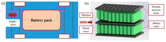
Figure 1.
Schematic diagram of the battery pack. (a) Some models have battery packs located at the bottom of the vehicle. (b) One type of battery package. The battery package includes battery units (blue part in middle) and connecting frames (black part on both sides).
In this paper, we propose a design of Metamaterial that enable simultaneous vibration. Specifically, the ABH structures are introduced to each cell wall of a conventional hexagonal lattice, which results in the reduction of local stiffness in the cell wall and the local mass in the hexagonal corner. Based on the finite element method (FEM), analyses are performed in terms of the bandgaps and the local eigenstates. Experiments on the finite periodic structure are carried out to validate the numerical results.
2. Model and Method
To demonstrate our concept, we use the standard unit cell of a hexagonal lattice, as shown in Figure 2a. The ABH structures are embedded into each edge of the hexagonal lattice by changing the local width. Figure 2b illustrates the local zoom image of one edge. In the new coordinate system x-o-y, the curve of ABH is driven by the power-law function y(x) = εxm + h0, and h0 is the residual thickness. The length xmax of half ABH is set as 0.016 m, the thickness of the micro beam h is set as 0.0173 m, and the maximum length of the micro beam L is set as 0.06 m. The lattice constant a is set to . A schematic of the irreducible Brillouin zone of the hexagonal lattice in the reciprocal space is shown in Figure 2c. Figure 2d,e shows the hexagonal cell array and the supercell of the hexagonal cell, respectively.
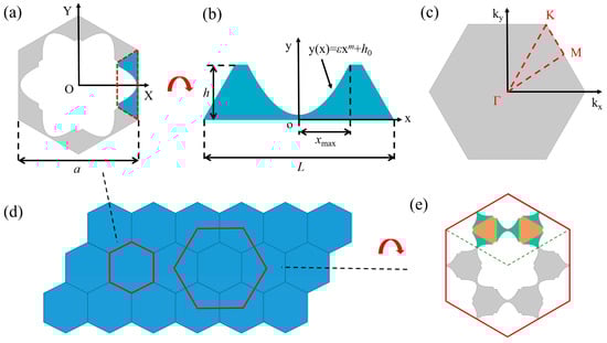
Figure 2.
Schematic diagram of the proposed 2D lattice. (a,b) The geometry of the 2D lattice embedded with ABHs at the middle of each hexagonal edge. The curve of ABH is driven by y(x) = 61.797x2 + 0.0015 m. (c) The red triangle shows the first irreducible Brillouin zone of the 2D lattice. (d,e) Periodic array composed of hexagonal unit cells and the supercell.
In order to analyze the dispersion relationship and transmission spectrum, the Finite Element Method (FEM) is applied to study the bandgap effect using the commercial software, COMSOL Multiphysics. The numerical values of the dispersion relations for the unit cell are obtained by solving the elastrodynamic boundary value problem:
where u is the displacement vector field and ω is the eigenfrequency. In the software, the band structure can be calculated by following steps. First, the Bloch-Floquet periodic boundary is considered as follows:
where kx and ky are the components of the Bloch wave vectors along the x and y directions in Figure 2c. ui is the displacement with i = x, y. The Bloch wavenumber kx and ky is scanned along Γ-K-M-Γ. Then, the dispersion relations and mode shapes can be obtained. The irreducible Brillouin Zone corresponds to the 2D lattice.
3. Results and Discussion
Figure 3 illustrates the phononic dispersion relations and the eigenstates of the lattice. Figure 3a shows the band structures of the lattice made of Polycarbonate, and it has two complete bandgaps from 5 kHz to 15 kHz, and from 18 kHz to 22 kHz. The width of the bandgap can be expressed using the gap-mid gap ratio, a non-dimensional parameter that avoids frequency dependence [29]
where ftop and fbot are the bounding frequency of the bandgap. The gap-mid ratios of the first two bandgaps are 98% and 20%. As the material changes to epoxy resin, the first bandgap width increases significantly, and ranges from 6.4 kHz to 19.3 kHz with a gap-mid gap ratio equal to 100% shown in Figure 3b. The second bandgap ranges from 23.5 kHz to 27.5 kHz. Compared with Figure 3a, when the ABH structure is removed in the hexagonal lattice edge, the band structures in Figure 3c have no bandgaps within 25 kHz. This result shows that the traditional hexagonal cell structure can’t attenuate the incident wave. On the contrary, if a designed structure is introduced into the traditional hexagonal lattice, it can be given a certain attenuation ability to waves and vibrations.
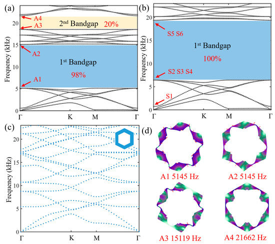
Figure 3.
Band structures of the lattice. The materials in (a,b) are polycarbonate (Young’s modulus E = 2.5 GPa, Poisson’s ratio ν = 0.35, and density ρ = 1100 kg/m3) and epoxy resin (Young’s modulus E = 4.35 GPa, Poisson’s ratio ν = 0.3, and density ρ = 1180 kg/m3), respectively. (c) The band structures of the reference hexagonal lattice. It is made of polycarbonate. Unit cells are depicted at the top right corner in the subfigure. (d) The associated displacement field distributions for the degenerated eigenstates at the Γ point.
Figure 4 illustrates the schematic diagram and Bloch modes of the simple lattice for Figure 3b. Due to the introduction of ABH structure at each edge of the hexagonal lattice, the stiffness of each edge of hexagonal lattice decreases, resulting in a local lumped mass at the junction of the three edges. It can be simplified as the form of lumped masses vibrating on springs, and the first six eigenstates: the rotational eigenstates S1 (717 Hz) and S2 (6442 Hz), and the transverse eigenstates S3 (6436 Hz), S4 (6436 Hz), S5 (19,365 Hz), and S6 (19,365 Hz), as shown in Figure 4d. The two lumped masses of State S1 rotate in opposite directions, and the rotation direction of two adjacent lumped masses in State S2 is the same. States S3 and S4 are the same eigenstates, and the phase difference of two adjacent masses is π. Five ABHs of each lattice are mainly subjected to tensile and compressive stress. Similarly, States S5 and S6 belong to the same kind eigenstate, but the phase difference of two adjacent masses is 0. Four ABHs of each lattice are mainly subjected to the shear stress, and one ABH structure is subjected to tensile and compressive stress.
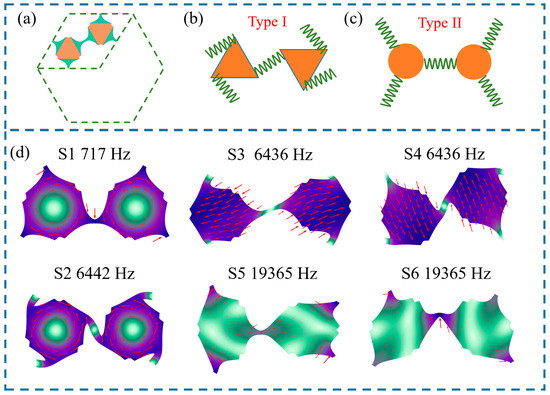
Figure 4.
Schematic diagram and eigenstates of the proposed 2D lattice. (a) The simplified lattice of supercell. It can be simplified as the form of lumped masses vibrating on springs: the rotational eigenstates (b) and transverse mode (c). (d) The eigenstates S1–S6 in Figure 3b.
Due to the introduction of ABH structures at the edge of the hexagonal lattice, the width of the edge is driven by the nonlinear power-law profile, resulting in the geometric nonlinearity and the non-uniformity of modal distribution. The first eigenfrequency is significantly reduced, but the latter eigenfrequency will be less affected, resulting in the wider attenuation band. Figure 5 illustrates the average decrease in lattice eigenfrequency and the width of the first bandgap as the parameter m increases. As m = 2, the frequencies of the shear state S3 (S4) and spinning state S2 are very close, which is accidental. As m increases to 10, the connecting part (ABH structures) is approximately equivalent to a uniform beam, and the bending stiffness decreases greatly, resulting in the lower rotational eigenstates (487 Hz and 2245 Hz) and transverse eigenstates (5097 Hz and 9790 Hz), which indicates that the first bandgap width changes to 5097 Hz–9790 Hz. It is worth noting that the influence of the variation of m on different eigenstates is different: the first rotation state (S1) and the first transverse eigenstates (S3, S4) are almost unaffected, and the second rotation state (S2) and the second transverse eigenstates (S5, S6) are significantly affected, which are reasonable. The increase of m leads to the decrease of the width at both ends of the ABHs, resulting in the reduction of bending stiffness at the ends. Different from state S2, state S1 is more sensitive to the lowest width because the deformation part is in the middle of the ABH structure. The deformation of the lumped masses in State S5 (S6) is much smaller than that in ABHs, and the vibration mode is represented by the local resonance of ABHs. Hence, state S5 (S6) is significantly affected.
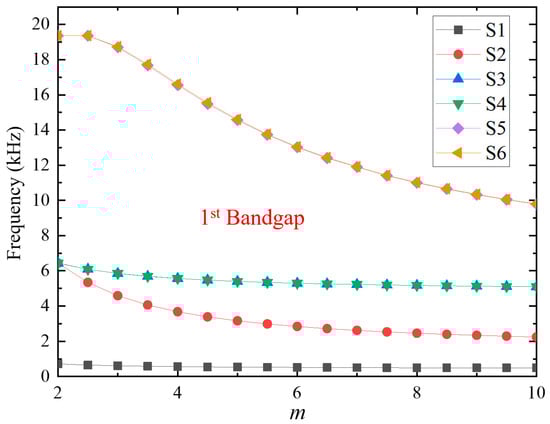
Figure 5.
Average decrease in lattice eigenfrequency as the parameter m increases.
To show the attenuation ability and the bandgaps of the finite periodic structure, simulations based on FEM and experiments have been carried out. Figure 6a,b shows the finite structure model (1 m × 1 m) consisting of 8 × 8 unit cells in the frequency domain. A 5 cm thick perfect matching layer (PML) marked with blue areas surrounds the finite structure. The 0.8 m load line was excited by a harmonic force of 1 N. Figure 6c shows the experimental prototype made of Polycarbonate, which was processed by the high-precision milling machine. The parameters of the lattice are consistent with the lattice parameters in Figure 3a. Six PZT-5H patches (25 mm × 20 mm × 1 mm) were pasted at three points on the left side of the prototype and driven by a power amplifier with a sweep signal source. During the experiment, the prototype was suspended by two strings to simulate the free boundary (see Figure S1 in the Supplementary Materials). The perforated structure on the plate is conducive to the measurement of the vibration response in the face. The velocity signals (the input side and output side) were measured by two laser vibrometers (Polytec PSV-400-3D). A good agreement between experimental results (red dotted line) and simulation results (blue dotted line) with PML in Figure 7 shows wide bandgaps. The transmission spectrum, in dB, is defined as 20log10(Aout/Ain), Aout and Ain are the output and input of acceleration amplitude. The damping effect of the material is not introduced in the aforementioned numerical calculations. However, the materials used in this case often have damping characteristics that can’t be ignored. As material loss factor is set to 0.01 and the PML is removed, the transmission spectrum is shown as the dark solid line in Figure 7, which is more in line with the experimental results. Compared with simulation results without damping, the peaks around 15 kHz in experimental results are attenuated to −20 dB due to the damping feature of materials, resulting in an ultra-wide bandgap from 4.5 kHz to 21 kHz. This design can be applied in the requirements, such as the battery package, which have periodicity. This structure can provide support for the battery units and has good vibration damping performance.
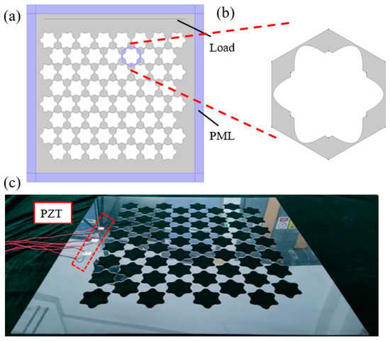
Figure 6.
The simulation configuration and the experimental setup. The finite structure model (a) (1 m × 1 m) consisting of 8 × 8 unit cells (b). The simulations were performed in the frequency domain. The load line was excited by a harmonic force of 1 N, and the perfect matching layer (PML) was applied marked with blue areas. (c) The experimental prototype made of polycarbonate was processed by the high-precision milling machine. Three PZT-5H patches were pasted on the left side and driven by a power amplifier with a sweep signal source.
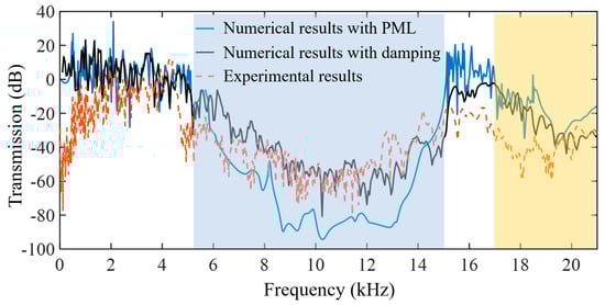
Figure 7.
The transmission spectrum of the finite periodic structure. Transmission comparison within 21 kHz between numerical results (blue and dark solid lines) and experimental results (red dotted line).
4. Conclusions
In this paper, we propose a design of metamaterial that attenuates the vibration and elastic waves in the structure. The traditional hollow hexagonal lattice is adopted as the frame. Specifically, the ABH structures are introduced to each cell wall of a conventional hexagonal lattice, resulting in a local mass in the hexagonal corner. The ultra-wide bandgap from 6 kHz to 19 kHz can be obtained by the numerical simulations. The first six eigenfrequencies (S1–S6) are shown and analyzed. The hexagonal lattice is simplified to two kinds of lumped mass vibrating on springs: the rotational mode and transverse mode. There are four modes (two rotational modes and two transverse modes) before the first ultra-wide bandgap, and the boundary modes after the bandgap are two transverse modes. Due to the geometric nonlinearity of ABHs, the frequency difference between two adjacent eigenstates is relatively huger than the traditional uniform beam, resulting in the ultra-wide bandgap. Experimental validations were carried out and showed good agreement with the numerical results. Compared with the traditional hexagonal lattice, the proposed design provides greater advantages in practical application.
Supplementary Materials
The following are available online at https://www.mdpi.com/article/10.3390/app112411788/s1, Figure S1. The experimental setup.
Author Contributions
Conceptualization, Q.D., Z.M. and T.Y.; investigation, X.L.; resources, Q.D.; writing—original draft preparation, X.L.; writing—review and editing, Z.M. and T.Y.; supervision, Q.D. All authors have read and agreed to the published version of the manuscript.
Funding
This work was supported by the Natural Science Foundation of China [grant numbers 12132010, 11972245, 12072221, 12021002].
Data Availability Statement
The data that support the findings of this study are available from the corresponding author upon reasonable request.
Conflicts of Interest
The authors declare no conflict of interest.
References
- Fischer, S.C.L.; Hillen, L.; Eberl, C. Mechanical Metamaterials on the Way from Laboratory Scale to Industrial Applications: Challenges for Characterization and Scalability. Materials 2020, 13, 3605. [Google Scholar] [CrossRef] [PubMed]
- Wu, L.; Wang, Y.; Chuang, K.; Wu, F.; Wang, Q.; Lin, W.; Jiang, H. A brief review of dynamic mechanical metamaterials for mechanical energy manipulation. Mater. Today 2020, 44, 168–193. [Google Scholar] [CrossRef]
- Ma, G.; Sheng, P. Acoustic metamaterials: From local resonances to broad horizons. Sci. Adv. 2016, 2, e1501595. [Google Scholar] [CrossRef] [Green Version]
- Tang, Y.; Ma, Z.-S.; Ding, Q.; Wang, T. Dynamic interaction between bi-directional functionally graded materials and magneto-electro-elastic fields: A nano-structure analysis. Compos. Struct. 2021, 264, 113746. [Google Scholar] [CrossRef]
- Chen, B.; Shiryayev, O.; Vahdati, N.; El-Sinawi, A. Validation of a Modeling Tool for In-Plane Longitudinal Resonators with Zigzag Topology. Int. J. Appl. Mech. 2019, 11, 1950013. [Google Scholar] [CrossRef]
- Cummer, S.A.; Christensen, J.; Alù, A. Controlling sound with acoustic metamaterials. Nat. Rev. Mater. 2016, 1, 16001. [Google Scholar] [CrossRef] [Green Version]
- Yan, D.; Chang, J.; Zhang, H.; Liu, J.; Song, H.; Xue, Z.; Zhang, F.; Zhang, Y. Soft three-dimensional network materials with rational bio-mimetic designs. Nat. Commun. 2020, 11, 1180. [Google Scholar] [CrossRef] [Green Version]
- Lu, M.-H.; Feng, L.; Chen, Y.-F. Phononic crystals and acoustic metamaterials. Mater. Today 2009, 12, 34–42. [Google Scholar] [CrossRef]
- Chang, I.-L.; Liang, Z.-X.; Kao, H.-W.; Chang, S.-H.; Yang, C.-Y. The wave attenuation mechanism of the periodic local resonant metamaterial. J. Sound Vib. 2018, 412, 349–359. [Google Scholar] [CrossRef]
- Wang, G.; Wen, X.; Wen, J.; Liu, Y. Quasi-One-Dimensional Periodic Structure with Locally Resonant Band Gap. J. Appl. Mech. 2005, 73, 167–170. [Google Scholar] [CrossRef]
- Wang, T.T.; Bargiel, S.; Lardet-Vieudrin, F.; Wang, Y.F.; Wang, Y.S.; Laude, V. Phononic Coupled-Resonator Waveguide Micro-Cavities. Appl. Sci. 2020, 10, 6751. [Google Scholar] [CrossRef]
- Faiz, M.S.; Addouche, M.; Zain, A.R.M.; Siow, K.S.; Chaalane, A.; Khelif, A. Experimental Demonstration of a Multichannel Elastic Wave Filter in a Phononic Crystal Slab. Appl. Sci. 2020, 10, 4594. [Google Scholar] [CrossRef]
- Xu, X.; Wang, C.; Shou, W.; Du, Z.; Chen, Y.; Li, B.; Matusik, W.; Hussein, N.; Huang, G. Physical Realization of Elastic Cloaking with a Polar Material. Phys. Rev. Lett. 2020, 124, 114301. [Google Scholar] [CrossRef] [PubMed]
- Wu, L.; Wang, Y.; Zhai, Z.; Yang, Y.; Krishnaraju, D.; Lu, J.; Wu, F.; Wang, Q.; Jiang, H. Mechanical metamaterials for full-band mechanical wave shielding. Appl. Mater. Today 2020, 20, 100671. [Google Scholar] [CrossRef]
- Aravantinos-Zafiris, N.; Lucklum, F.; Sigalas, M.M. Complete phononic band gaps in the 3D Yablonovite structure with spheres. Ultrasonics 2020, 110, 106265. [Google Scholar] [CrossRef]
- Wormser, M.; Wein, F.; Stingl, M.; Körner, C. Design and Additive Manufacturing of 3D Phononic Band Gap Structures Based on Gradient Based Optimization. Materials 2017, 10, 1125. [Google Scholar] [CrossRef]
- Jia, Z.; Chen, Y.; Yang, H.; Wang, L. Designing Phononic Crystals with Wide and Robust Band Gaps. Phys. Rev. Appl. 2018, 9, 044021. [Google Scholar] [CrossRef] [Green Version]
- Wang, T.T.; Laude, V.; Kadic, M.; Wang, Y.F.; Wang, Y.S. Complex-Eigenfrequency Band Structure of Viscoelastic Phononic Crystals. Appl. Sci. 2019, 9, 2825. [Google Scholar] [CrossRef] [Green Version]
- Li, Y.; Baker, E.; Reissman, T.; Sun, C.; Liu, W.K. Design of mechanical metamaterials for simultaneous vibration isolation and energy harvesting. Appl. Phys. Lett. 2017, 111, 251903. [Google Scholar] [CrossRef]
- Zhao, C.; Gao, X.; Wang, L.; Yi, Q.; Wang, P. A study of the vibration isolation performance of a limited phononic crystal vibration isolator based on local resonance theory. J. Appl. Phys. 2020, 128, 134903. [Google Scholar] [CrossRef]
- Ruan, Y.; Liang, X.; Hua, X.; Zhang, C.; Xia, H.; Li, C. Isolating low-frequency vibration from power systems on a ship using spiral phononic crystals. Ocean Eng. 2021, 225, 108804. [Google Scholar] [CrossRef]
- Zhang, Q.; Guo, D.; Hu, G. Tailored Mechanical Metamaterials with Programmable Quasi-Zero-Stiffness Features for Full-Band Vibration Isolation. Adv. Funct. Mater. 2021, 31, 2101428. [Google Scholar] [CrossRef]
- Tang, L.; Cheng, L. Broadband locally resonant band gaps in periodic beam structures with embedded acoustic black holes. J. Appl. Phys. 2017, 121, 194901. [Google Scholar] [CrossRef]
- Lyu, X.; Ding, Q.; Yang, T. Merging phononic crystals and acoustic black holes. Appl. Math. Mech. 2019, 41, 279–288. [Google Scholar] [CrossRef]
- Deng, J.; Zheng, L.; Zeng, P.; Zuo, Y.; Guasch, O. Passive constrained viscoelastic layers to improve the efficiency of truncated acoustic black holes in beams. Mech. Syst. Signal Process. 2018, 118, 461–476. [Google Scholar] [CrossRef]
- Lyu, X.; Li, H.; Ma, Z.; Ding, Q.; Yang, T.; Chen, L.; Żur, K.K. Numerical and experimental evidence of topological interface state in a periodic acoustic black hole. J. Sound Vib. 2021, 514, 116432. [Google Scholar] [CrossRef]
- Ganti, S.S.; Liu, T.-W.; Semperlotti, F. Topological edge states in phononic plates with embedded acoustic black holes. J. Sound Vib. 2019, 466, 115060. [Google Scholar] [CrossRef]
- Chen, Y.; Wang, L. Harnessing structural hierarchy to design stiff and lightweight phononic crystals. Extreme Mech. Lett. 2016, 9, 91–96. [Google Scholar] [CrossRef] [Green Version]
- D’Alessandro, L.; Belloni, E.; Ardito, R.; Corigliano, A.; Braghin, F. Modeling and experimental verification of an ultra-wide bandgap in 3D phononic crystal. Appl. Phys. Lett. 2016, 109, 221907. [Google Scholar] [CrossRef] [Green Version]
Publisher’s Note: MDPI stays neutral with regard to jurisdictional claims in published maps and institutional affiliations. |
© 2021 by the authors. Licensee MDPI, Basel, Switzerland. This article is an open access article distributed under the terms and conditions of the Creative Commons Attribution (CC BY) license (https://creativecommons.org/licenses/by/4.0/).