The airbearing moments, tilting stiffness, and damping were calculated for
,
,
, and
, respectively; with
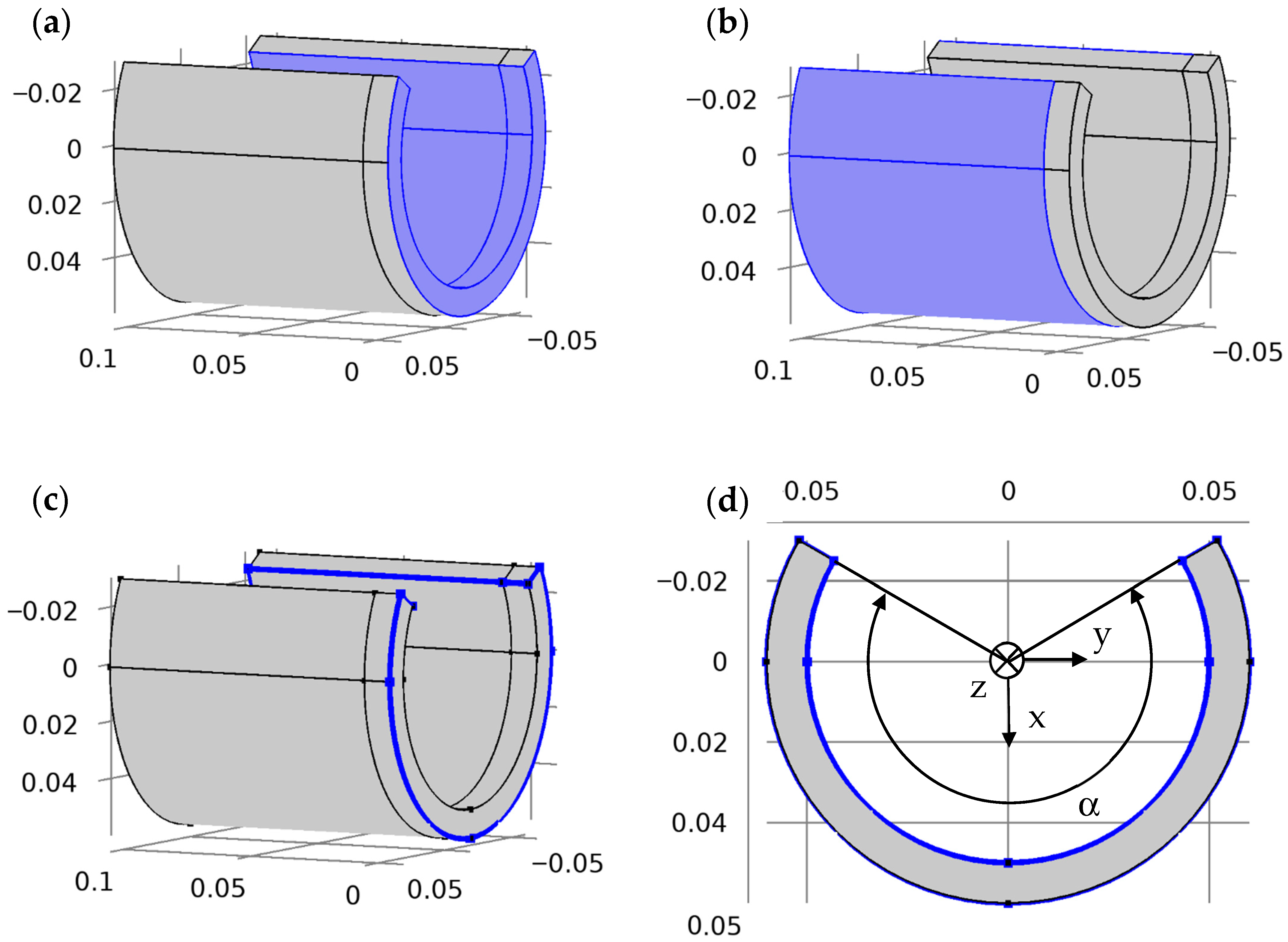
, bearing length
L = 0.11 m, shaft diameter
D = 0.1 m, porous cylinder thickness
b = 0.01 m, clearance
c = 10 μm, rotation speed = 1000 rpm, bearing arc α = 240°, porosity = 0.4, and permeability =
m
2. The film variation due to tilting in the given range does not exceed 57% for simultaneous change of
and
. Together with 30% variation due to eccentricity, it gives a minimal film thickness of 13% of clearance, or 1.3 μm. The air-bearing pressure, forces, and moments were calculated for all combinations of parameters
,
,
, and
, and their combinations with the following pairs of tilting velocity values:
. The total number of cases was 13000. The steps in the differences (12–19) were
, and
. The maximum and average absolute errors of the finite differences are presented in
Table 1.
3.1. Preliminary Analysis
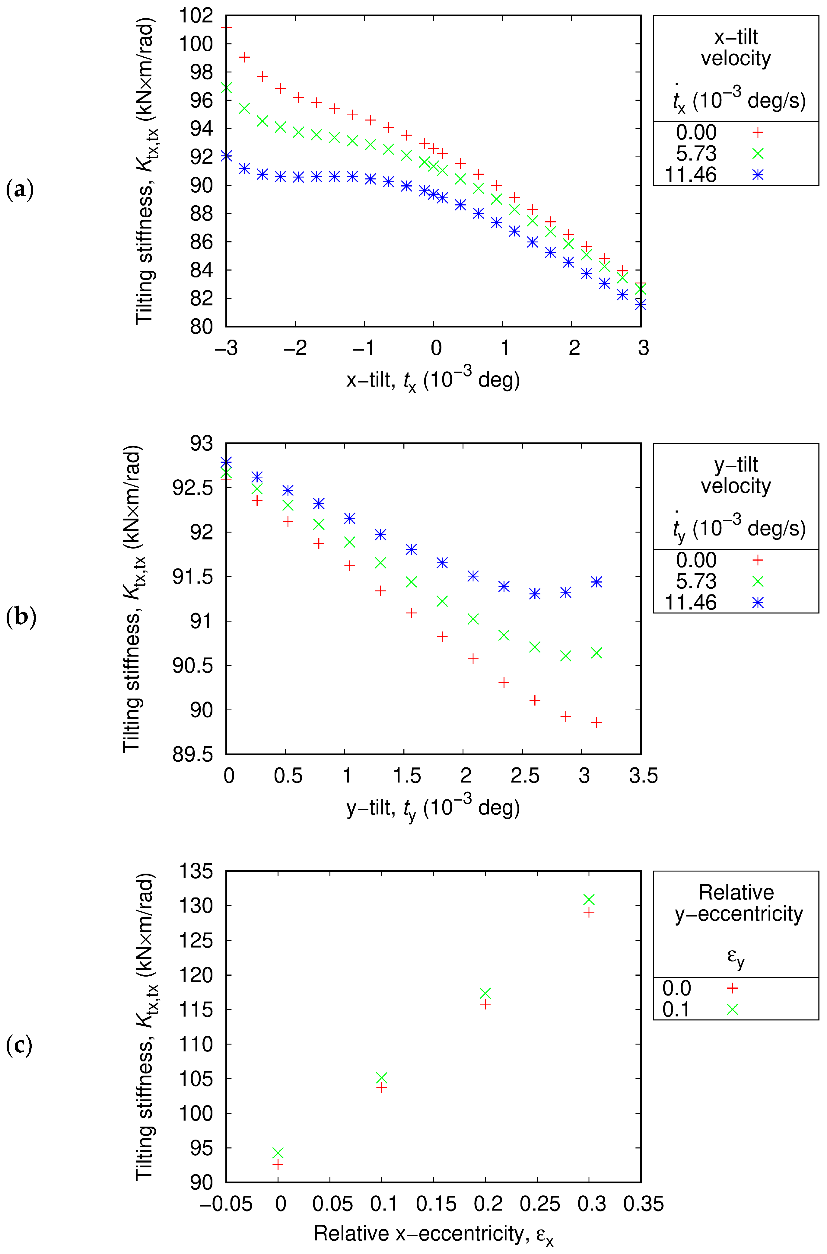
As illustrated in
Figure 4, the direct stiffness coefficient
Ktx,tx has values in the range of 80–140 kN·m/rad. Within the range under consideration,
Ktx,tx depends linearly on
and nonlinearly on
,
,
,
. The parameters
,
, and
exhibit significant effects (more than 10%).
Ktx,tx is almost insensitive to
at low negative tilting angles; however, it decreases linearly with
at positive and high negative tilting angles (see
Figure 4a). The effect of the x-tilting velocity
is the diminishing of
Ktx,tx, which is more significant at negative tilting angles.
Ktx,tx increases with decreasing
, increasing
and
, and is insensible to
(see
Figure 4b,c).
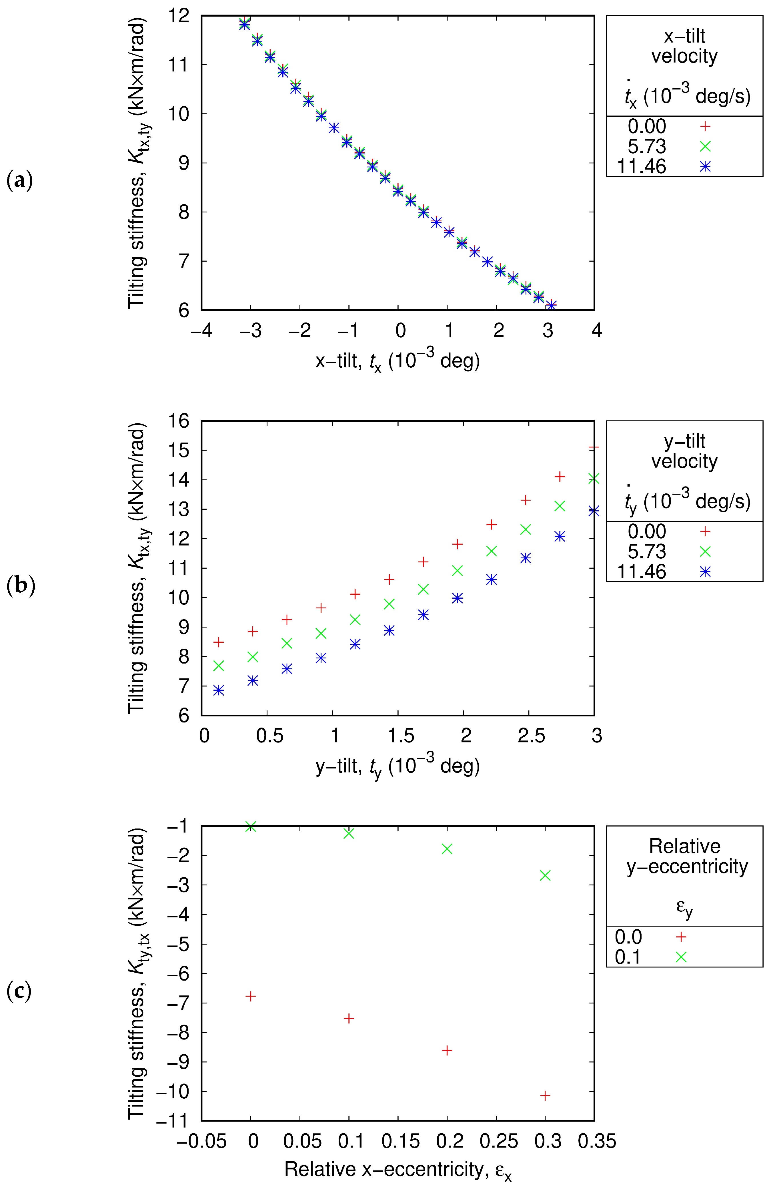
The cross-coupled stiffness coefficient
Ktx,ty is approximately 10 times smaller than the direct stiffness coefficient
Ktx,tx, and lies in the range of 6–15 kN·m/rad (see
Figure 5). It is highly sensitive to all parameters, except for
.
Ktx,ty increases with decreasing
and
, and increasing
(see
Figure 5a,b). Eccentricity
can increase or decrease
Ktx,ty, depending on
(see
Figure 5c).
Kty,tx, which is another cross-coupled stiffness coefficient, is of the same order of magnitude; however, it is negative, and falls in the range of −18–0 kN·m/rad (refer to
Figure 6). It is not sensitive to
, and the
effect on it is also negligible (see
Figure 6a,b). The magnitude of
Kty,tx is higher at lower
and
and at higher
and
The direct stiffness coefficient
Kty,ty is higher than that of
Ktx,tx.
Kty,ty falls in the range of 110–140 kN·m/rad (refer to
Figure 7). This is triggered by the cut arc, which increases force and decreases the stiffness in the x-direction [
27]. The y-tilting angle
exerts a strong nonlinear effect on
Kty,ty. The stiffness coefficient
Kty,ty is almost constant for a low positive
, and then increases with increasing
. In contrast to
Ktx,tx, which is primarily sensitive to “its own” parameter
and significantly less sensitive to
.
Kty,ty is equally sensitive to both
and
. In addition, it is equally sensitive to both higher
and
, with a negligible
effect, and no
effect. Furthermore, it is higher for lower
and higher
, and
.
Because the simultaneous variation of tilting velocities was not studied, the effect of
was solely studied for
Dtx,tx and
Dty,tx, while the effect of
was solely studied for
Dtx,ty and
Dty,ty. Instead of the missing parameter, the coupling between
and
is comprehensively presented in
Figure 8,
Figure 9,
Figure 10 and
Figure 11.
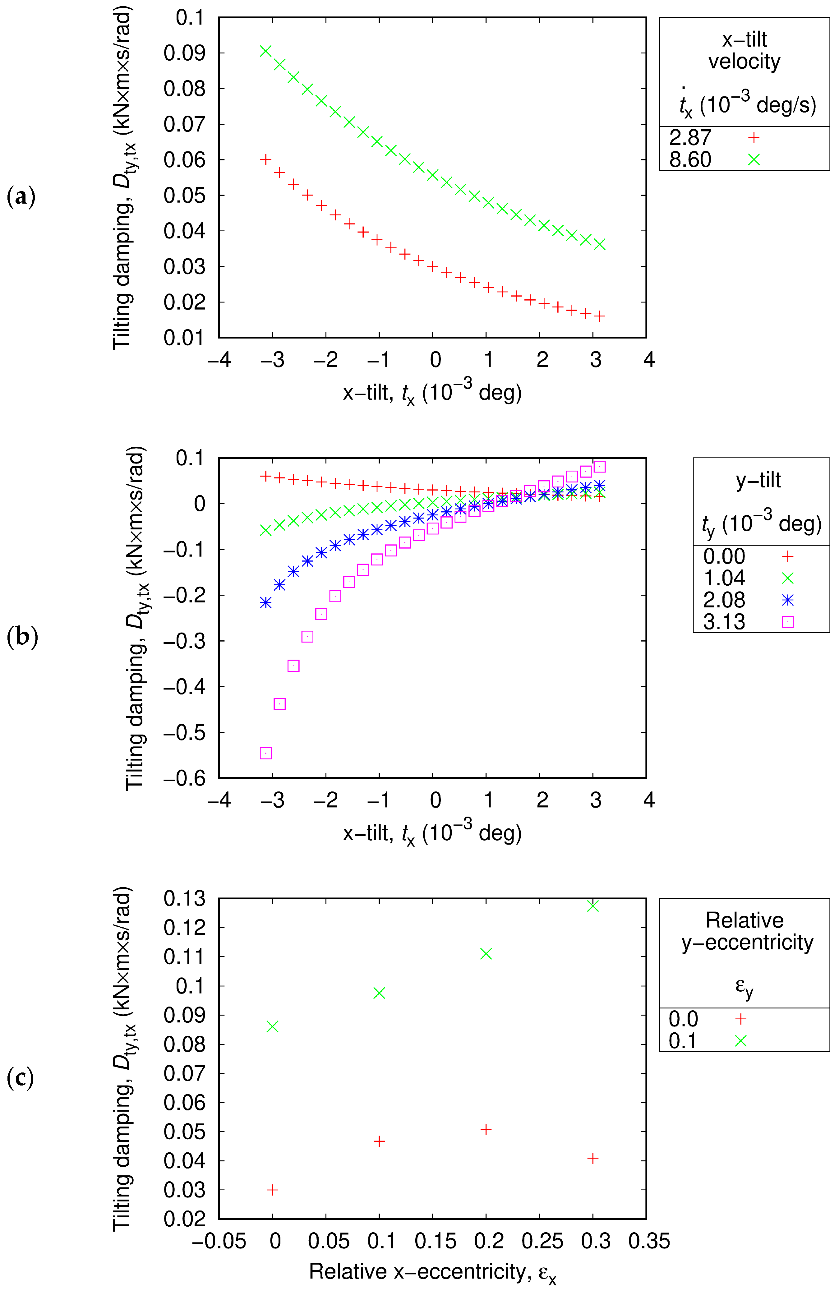
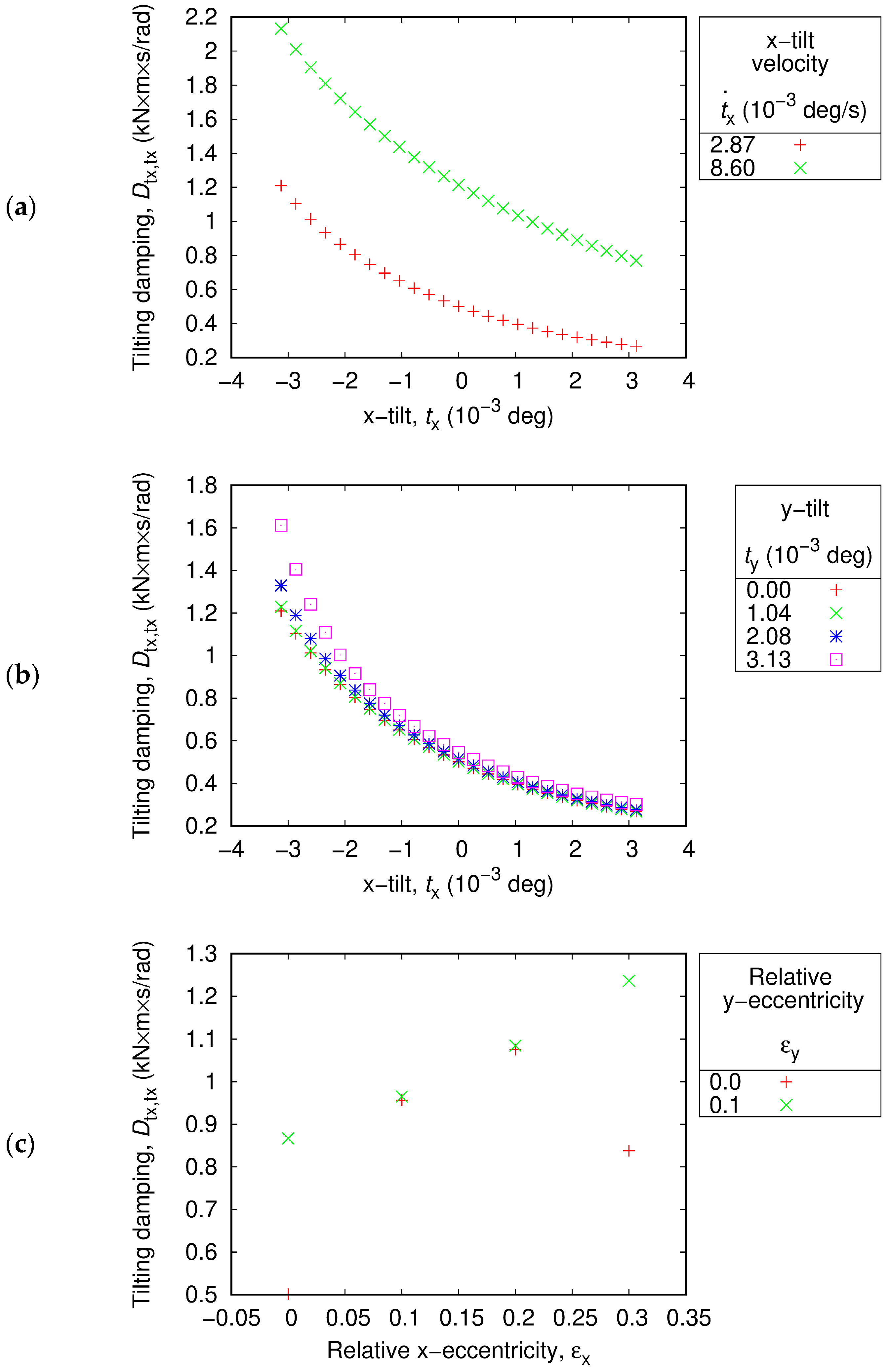
The direct damping coefficient
Dtx,tx is positive and falls in the range 0.2–2.2 kN·m s/rad (refer to
Figure 8). It is higher for lower
, and higher
and higher
(see
Figure 8a,b). The effect of eccentricity is also substantial, nonlinear, and strongly coupled between
and
(see
Figure 8c).
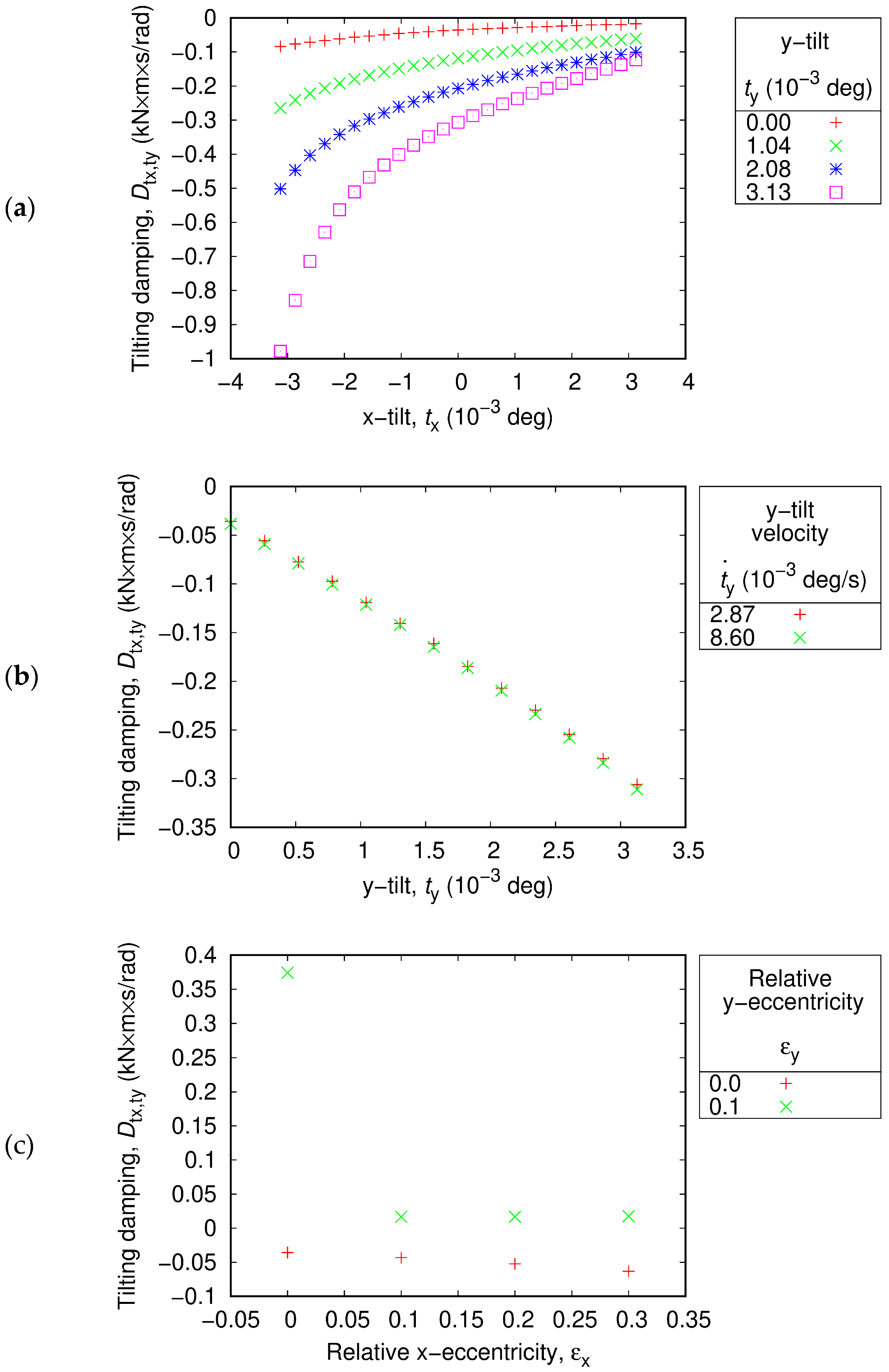
The cross-coupled damping coefficient
Dtx,ty does not exceed 1 kN m s/rad in magnitude, being mostly negative (see
Figure 9).
Dtx,ty rapidly decreases with decreasing
or increasing
in the negative
range, while in the positive
range, it is much less sensible both to
and
(see
Figure 9a).
Dtx,ty decreases with increasing
and is almost insensible to
(see
Figure 9b). The dependence of
Dtx,ty on eccentricity parameters is highly nonlinear.
Dtx,ty can take relatively high positive values for zero
. and positive
, but in most of the range, the sensitivity to
and
is low (see
Figure 9c).
The cross-coupled damping coefficient
Dty,tx falls in the range −0.6–0.13 kN m s/rad (see
Figure 10). It is negative for positive
and negative
, otherwise it is positive. Similar to
Dtx,ty,
Dty,tx rapidly decreases with decreasing
or increasing
in the negative
range, while in the positive
range, it is much less sensible both to
and
. However, for
> 0.002 °,
Dty,tx increases with increasing
(see
Figure 10b), while
Dtx,ty decreases with increasing
for any
(see
Figure 9a). For zero
Dty,tx decreases with increasing
and decreasing
. Similar to all previously considered damping coefficients, the dependence of
Dty,tx on the eccentricity parameters is highly nonlinear.
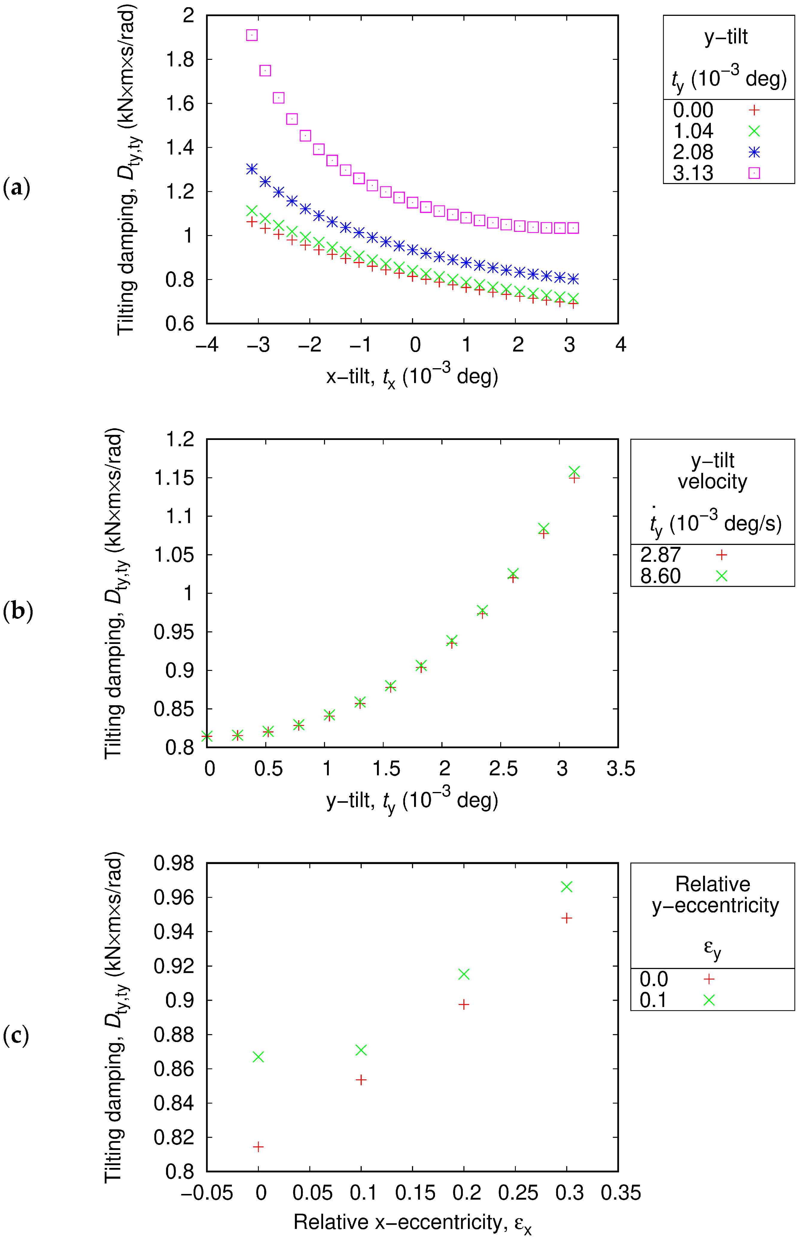
In contrast with all other damping coefficients, the direct damping coefficient
Dty,ty does not significantly depend on
and
(refer to
Figure 11). It falls in the range 0.6–2.0 kN·m s/rad. It is higher for lower
, and higher
, similar to
Dtx,tx.
Dty,ty is almost insensible to the y-tilt velocity
. It slightly increases with increasing
and increasing
In summary, the direct stiffness and damping coefficients were positive. The cross-coupled stiffness coefficients are approximately 10 times smaller than the direct stiffness coefficients, and the cross-coupled damping coefficients are approximately 2–3 times smaller than the direct damping coefficients. Hence, a stable tilting motion was expected. However, information on the rotor inertia and the bearing at the other end is required to make precise conclusions on the dynamic behavior. Moreover, the results above exhibit a strong coupling between the eccentricity and tilting motion, including the nonlinearity of the moments relative to the position parameters. This can make the rotor motion severely complicated.


