Article

Zoning Control Technology of Gob-Side Roadway Driving with Small Coal Pillar Facing Mining in a Special Isolated Island Working Face: A Case Study

1
Key Laboratory of Deep Coal Resource Mining, Ministry of Education of China, School of Mines, China University of Mining and Technology, Xuzhou 221116, China
2
Open Laboratory for Large-Scale Scientific Instruments, Jiangsu Normal University, Xuzhou 221116, China
*
Author to whom correspondence should be addressed.
Appl. Sci. 2021, 11(22), 10744; https://doi.org/10.3390/app112210744
Submission received: 29 September 2021 / Revised: 8 November 2021 / Accepted: 11 November 2021 / Published: 14 November 2021

Abstract

:
The gob-side roadway in an isolated island working face is a typical representative of a strong mining roadway, which seriously restricts the efficient and safe production of underground coal mines. With the engineering background of the main transportation roadway 1513 (MTR 1513) of the Xinyi Coal Mine, this paper introduces the engineering case of gob-side roadway driving with small coal-pillar facing mining in an isolated island working face under the alternate mining of wide and narrow working faces. Through comprehensive research methods, we studied zoning disturbance deformation characteristics and stress evolution law of gob-side roadway driving under face mining. Based on the characteristics of zoning disturbance, MTR 1513 is divided into three zones, which are the heading face mining zone, the mining influenced zone, and the mining stability zone. A collaborative control technology using pressure relief and anchoring is proposed, and the differentiated control method is formed for the three zones. For the heading face mining zone, the control method of anchoring first and then pressure relief is adopted; for the mining influenced zone, the control idea of synchronous coordination of pressure relief and anchorage is adopted; for the mining stability zone, the control method of anchoring without pressure relief is adopted. Engineering practices show that the disturbance influence distance of working face 1511 on MTR 1513 changes from 110 m advanced to 175 m delay. At this time, the surrounding rock deformation is effectively controlled, which verified the rationality of the division and the feasibility of three zoning control technology. The research results can provide reference for gob-side roadway driving with small coal pillar facing mining in a special isolated island working face.

1. Introduction

The gob-side roadway in an isolated island working face is a typical representative of a strong mining roadway [1], whose surrounding rock control problem is one of the major technical challenges that restricts underground coal mines. As the mine service cycle extends and mining conditions deteriorate, these kind of roadways are faced with a more complex and difficult supporting surrounding [2,3]. As a result, the roadway suffers severe shrinkage and deformation, along with increased maintenance costs and frequent repair work, which exerts a serious impact on the normal production of the mine.
Many scholars have conducted a host of studies on supporting problems of isolated island working faces or gob-side roadways. Research on isolated island working faces mainly focuses on the roof movement structure, as well as the stress evolution and distribution characteristics of surrounding rock. Dou et al. [4] divided the overlying strata spatial structure into three types, which are “OX” type, “F” type, and “T” type, according to the different boundary states of overlying strata on working surfaces. They also studied the evolution characteristics of “OX-F-T” type, that is, the “OX” type structure formed by roof “O-X” type fracture is the basic form of overlying strata. At this time, in the boundary condition of adjacent working faces, the “OX” type structure on one side forms the “F” type overlying strata structure, and the “OX” type structure on both sides forms the “T” type overlying strata structure [4]. Jiang et al. put forward the calculation formula of abutment pressure and an instability analysis method of coal body in the isolated island working face. It was concluded that the stress reaches the maximum when the lateral goaf of the isolated island working face changes from suspended roof to semi-suspended roof structure, while the stress decreases when the goaf width becomes large enough (entering the full mining stage) [5]. Cao et al. reported that the working face was an asymmetric “T” type isolated island overburden structure on the vertical section, whose long arm side was prone to large-scale breaking movement of key strata, making it more likely to induce strong mine earthquakes and rock bursts. On the horizontal level, the inferior key strata broke to form an “O” type fracture structure, while the thick main critical strata broke in a large scale “OX” mode. The gradual breaking and movement of key strata at all levels were main power source of mine earthquake activities [6]. Zhang et al. studied the maximum peak value of advanced abutment pressure of gob-side roadway driving in isolated island working face, finding that it was significantly higher than that in conventional working face, and the stress concentration coefficient was 1.84 times that in conventional working face [7].
With a determined width of coal pillar, research on the supporting problem of gob-side roadways has mainly focused on the time–space relationship of mining, the determination of support parameters, and pressure relief technologies. In terms of mining time and space, Bai et al. reported that the middle part of the roof was the key point of support in gob-side roadway driving with small coal pillar facing mining, and put forward three key technologies to improve supporting efficiency, as follows: setting a reasonable coal pillar width; stopping driving in dynamic pressure-affected areas under face mining and restart driving at the end of influence; providing dynamic support in stages [8]. Ma et al. studied the reasonable space–time relationship between gob-side roadway driving and mining face, finding the following: when driving is conducted, the reasonable delay distance of roadway is 136 m and the delay days should not be less than 36 days; when driving and mining are in opposite directions, the distance between the roadway and the stop line should be less than 50 m [9]. In terms of the determination of support parameters, Zhang et al. put forward the ‘trinity’ coupling support technology of gob-side roadway driving, that is, using high prestressed screw steel bolt supports in advance in the goaf side. Moreover, a short bolt support was applied to the coal pillar in the gob driving roadway, and a deep injection is applied to the coal body to strengthen the anchoring point, so as to restrict the expansion of the coal body [10]. Yin et al. proposed the supporting technologies of a roof anchor truss and a narrow coal pillar anchor beam for gob-side roadway driving with small coal pillar, which achieved a good supporting effect in situ [11]. Yang et al. pointed out that in the gob-side roadway with small coal pillar, supporting conditions differed largely in roof, solid coal side, and narrow coal pillar side. Asymmetric control technology with different density of surrounding rock support was proposed, in which the support density of narrow coal pillar was increased [12]. In terms of pressure relief technology, after studying the relationship between the filling body of gob-side roadway retaining and the fracture position of key roof blocks, Li et al. pointed out that when the roof strata were pre-splitting, the optimal direct roof strength that could promote the stability of the filling body could be obtained, which clarifies the significance of pre-splitting roof strata at an appropriate position [13].
He analyzed the mechanism of pressure relief roadway layout in this coal seam on surrounding rock pressure relief of fully mechanized caving gob-side roadways. The essence of pressure relief control of gob-side roadways is to transfer the high stress zone of the surrounding rock to the deep coal body along the tendency. Furthermore, the position of the pressure relief roadway and the loose blasting strength were the key points of pressure relief technology [14]. Li et al. found that the working face of an isolated island corner coal pillar with three side goaf showed an anti-arc overburden structure, composed of “T” shape and “T” shape, which made the coal pillar form an anti-arc, high stress, and elastic energy accumulation area around the working face. In the process of mining, the periodic movement of the “r” shape hanging roof led to the dynamic change of the anti-arc overburden structure. The comprehensive effect of dynamic and static stress on the stability of coal bodies was the main reason for inducing rock bursts. The asymmetric control measure of pressure relief weakening on the solid coal side of a gob-side roadway, and supporting strengthening on the narrow coal pillar side were proposed, which could reduce the influence of anti-arc overburden structure and control the impact danger [15].
The above research expounded the surrounding rock structure and control mechanisms of isolated island working faces or gob-side roadways in different aspects, laying a theoretical foundation for further study on surrounding rock control of gob-side roadway under complex conditions. However, in the existing research, there is still a lack of research on the spatial–temporal relationship and zoning control technology of gob-side roadway driving with small coal pillars in the isolated island working, under face mining, in the alternate mining of wide and narrow working faces. Combined with typical engineering cases, this paper clarifies the zoning disturbance deformation characteristics and stress evolution law of gob-side roadway driving in such special isolated island working face. Based on this, the roadway is divided into several zones, after which the zoning control technology is put forward, along with the engineering verification.

2. Engineering Overview

2.1. Basic Conditions of Roadway

The Xinyi Coal Mine in Jining, Shandong, China, with an average buried depth of 507 m and an average thickness of 3.11 m in the working face of the main coal seam (i.e., 3up coal seam), was studied. The lithology of the coal roof and floor was mainly mudstone, siltstone, and sandstone [16]. In order to reduce the obvious surface subsidence and protect village relocation, the alternative mining of wide and narrow working faces was adopted in the mine [16]. The widths of working faces 1511 and 1513 were 200 m, and the widths of working faces 1512 and 1514 were 40~60 m, with the value of 40 m adopted in this study.
As shown in Figure 1, goaf 1512 and goaf 1514 were located at two sides of the working face 1513, surrounded by an isolated island working face, called “isolated island working face”. The test roadway was MTR 1513, which was excavated by setting 6 m coal pillar at the edge of goaf 1512. During the excavation, the working face 1511 was being mined, whose mining direction was opposite to that of MTR 1513. Due to the small width of goaf 1512, the mining of working face 1511 will cause lateral stress disturbance on the MTR 1513, so the MTR 1513 belongs to gob-side roadway driving with small coal pillar facing mining in the isolated island working face under the alternate mining of wide and narrow working faces. Due to its particularity and complexity, the engineering of geological conditions of gob-side roadway driving with small coal pillar facing mining in special island working faces is very rare in China.

2.2. Roadway Deformation Characteristics

The auxiliary transportation roadway 1511 (ATR 1511) was also a small coal pillar gob-side roadway driving in this special isolated island working face, which was consistent with the engineering geological conditions of MTR 1513. Therefore, this section analyses the deformation characteristics of surrounding rock of ATR 1511 under the influence of mining stress. The deformation law of ATR 1511 is shown in Figure 2 (obtained from in situ monitoring). The negative number in the abscissa represents the displacement monitoring point in front of the adjacent mining work, while the positive number represents the displacement monitoring point in the rear of the adjacent mining face.
Before meeting with the adjacent working face, the deformation speed of the roadway surrounding rock was relatively slow. When the distance exceeds 100 m, before the encounter with the adjacent working face, the displacement of the roadway roof and two sides does not exceed 100 mm. When the distance is 0~100 m before the encounter, the deformation speed of the roadway surrounding rock begins to accelerate, due to the strong influence of the advance mining of adjacent working faces. When the monitoring point meets with the adjacent working face and staggers until 180 m, the deformation of the roadway surrounding rock tends to be stable. After stability, the maximum deformation of the roof is 514 mm, the maximum deformation of the coal pillar is 910 mm, and the maximum deformation of the solid coal is 473 mm.
According to the deformation characteristics of the surrounding rock of ATR 1511 under the mining influence of adjacent working face, the disturbance influences can be divided into two stages. The first stage was the advanced influence stage of working faces, and the second stage was the delayed influence stage of working faces. As can be seen from Figure 2, the advanced influence range of adjacent working face roadway was 100 m, while the delayed influence range was 180 m, and the delayed mining stress influence was stronger than the advanced mining stress.

3. Zoning Principle and Zoning Results of a Gob-Side Roadway Driving under Face Mining

3.1. Analysis of the Stress Evolution Characteristics of a Gob-Side Roadway Driving under Face Mining

3.1.1. Model Establishment

Based on the engineering background of MTR 1513, working face 1512, and adjacent working face 1511, the FLAC3 D finite element numerical calculation model (Figure 3) was established to study the stress disturbance law of MTR 1513 under the mining influence of adjacent working face 1511. The model is 400 m in length (x direction), 80 m in height (z direction) and 200 m in width (y direction), among which 200 m in width of 1511 working face, 40 m in width of working face 1512, and 4 m by 3.4 m in width by height of MTR 1513. All the element meshes of the model are rectangular meshes, with a total of element meshes. According to the buried depth of coal seam, the simulated ground stress of coal seam is 12.675 MPa, the gradient in the vertical direction of vertical stress is 0.025 MPa/m, and the lateral pressure coefficient is 1.1. The Mohr–Coulomb criterion was used for model calculation. Lithology occurrence and mechanical parameters are shown in Table 1 [16,17].

3.1.2. Simulation Methods

The simulation sequence was as follows: (1) Mining working face 1512 and forming goaf 1512 with a width of 40 m. (2) Excavating 100 m of MTR 1513 after setting 6 m coal pillar near the goaf 1512 and mining 50 m of working face 1511. At this time, the roadway excavating working face was located 50 m before the working face 1511. (3) Excavating 100 m of MTR 1513 and mining 100 m of working face 1511. At this time, the roadway excavating working face displacement and working face 1511 displacement in the same horizontal line. (4) Excavating 200 m of MTR 1513 and mining 150 m of working face 1511. At this time, the roadway excavating working face was located 150 m behind the working face 1511.

3.1.3. Results Analysis

The 3D stress nephogram of coal seam 1 m away from the roof (x = 0~400 m; y = 0~200 m; z = 35.2 m), as obtained by the four calculation steps mentioned in Section 3.1.2, is shown in Figure 4. The working face 1512 was located at x = 120~160 m, and the MTR 1513 was located at x = 104~160 m.
(1) After finishing the mining of working face 1512, the vertical stress distribution of the stope continues to fluctuate with the mining of the working face, and the vertical stress field presents a “hump-like” shape on the “coal pillar–stope–coal pillar” (Figure 4a). After mining, the stress in the goaf was transferred to the surrounding area. The vertical stress forms a low stress area, a high stress area, and an original rock stress area in the direction of the coal pillar after stress redistribution.
(2) In the process of MTR 1513 excavating, the left side (solid coal side) and the front of the roadway were in the high stress area (Figure 4e). Due to the influence of the advanced support stress of the working face 1511 (Figure 4b), the stress concentration of the working face was obvious (Figure 4b,c). The stress at the head of roadway presents a sharp triangle, and the stress peak point was located in the center of the roadway.
(3) When the roadway excavating working face was located behind working face1511, its entity coal side shows obvious stress concentration (Figure 4d) affected by delayed mining stress of working face 1511. Besides, the stress value was greater than the stress value of the solid coal side within the influence range of the advanced mining of the working face 1511. It shows that the mining of working face 1511 exerts more delayed mining influence than advanced mining influence on MTR 1513, which verifies the deformation law of the roadway, affected by adjacent working face in Section 2.2.

3.2. Zoning Principle and Result of Gob-Side Roadway Driving under Face Mining

According to the two disturbance-affected stages of roadways surrounding the rock deformation in Section 2.2 and the stress disturbance evolution characteristics of the gob-side roadway driving in Section 3.1—due to the different influence degree of mining stress of adjacent working faces in different roadway areas—the stress and deformation of surrounding rock in different areas show obvious differences, so different control technical ideas need to be adopted.
As shown in Figure 5, the first zone was the heading face mining zone (Zone A), in which the working face was beyond 100 m ahead, that is, the roadway section was not affected by the mining stress of the adjacent working face. However, with the continuous advancement of the adjacent working face, the roadway will be affected by mining stress later. The second zone was the mining influenced zone (Zone B), that is, the range from 100 m ahead of the working face to 180 m behind the working face. This stage was the area with severe mining influence. In this area, the roadway was affected by the mining stress of the adjacent working face, and the deformation speed begins to accelerate, along with large displacement.
The third zone was the mining stability zone (Zone C), that is, the working face delays 180 m behind. As the encounter with the working face and staggering to the roadway section beyond 180 m, the mining influence tends to be stable in this range, and the deformation of roadway surrounding rock tends to be stable, escaping being affected by the mining stress.

4. Zoning Control Principle and Cooperative Control Technical Scheme of Pressure Relief and Anchorage

4.1. Cooperative Control Technology of Pressure Relief and Anchorage

4.1.1. Pressure Relief Technology of Roadway Solid Coal Side

The roadway section of MTR 1513 that strongly affected by the mining of working face 1511 shows obvious stress concentration of surrounding rock. Through borehole pressure relief in the solid coal side (Figure 6), the mining stress transfers to the deep with guidance, which alleviates the stress concentration of the surrounding roadway.
In order to simulate and analyze the borehole pressure relief effect of the solid coal side of MTR 1513 before and after the mining of 1511 working face, the numerical calculation model of UDEC plane stress was established, and the boundary conditions and rock parameters of the model were consistent with the above FLAC3D calculation model. The diameter and depth of the pressure relief hole were 100 mm and 10 m, respectively. After the excavation of MTR 1513, the vertical stress distributions 1.4 m above the roof of the roadway entity coal side were monitored under the following conditions: before mining working face 1511; after mining working face 1511, while without pressure relief of entity coal side in MTR1513; after mining working face 1511, with pressure relief of entity coal side in MTR1513, the monitoring results are shown in Figure 7. The deformation of the pressure relief hole before and after mining in working face 1511 is shown in Figure 8.
(1) Considering that working face 1511 exerts stress disturbance influence on MTR 1513, the vertical stress of the roof in the 10 m range of the solid coal side of the roadway increases significantly (Figure 7), after the mining of 1511 working face (without pressure relief).
(2) After borehole pressure relief was adopted for the solid coal side of MTR 1513, the deformation of pressure relief borehole was relatively sufficient under the influence of mining stress of working face 1511 (Figure 8). The vertical stress of the roof decreases obviously within 10 m of the solid coal side of the roadway—the vertical stress value of the roof at 1 m deep of the solid coal side decreases from 41 MPa before pressure relief to 29 MPa after pressure relief; the vertical stress value of the roof at the depth of 8 m on the solid coal side decreases from 25 MPa before pressure relief to 13 MPa after pressure relief. The pressure relief effect was pronounced, and the peak point shifts to the depth.

4.1.2. Coordinated Bearing Support Technology of Thick Roof Anchored with Double Circle Layer

The fractures in the surrounding rock of the gob-side roadway were developed and seriously damaged. After the roadway was excavated, there will be a ring with relatively developed fractures in the surrounding rock of the roadway. Through increasing the length of roof and coal wall bolts, the bearing ring of shallow rock foundation was constructed, which could pass through the rock mass fracture ring to the stable rock stratum with small deformation. The small displacement of deep rock stratum was used to restrain the large displacement of shallow rock stratum, to realize the linkage of large displacement and small displacement [18,19,20].
According to the FLAC3D numerical simulation results in Section 3.1, the mining of 1511 working face caused strong stress disturbance to MTR 1513. Especially for the roadway roof, the ability of single anchor layer to resist stress disturbance was low. Therefore, on the basis of constructing the bearing ring of shallow rock foundation, a reinforced bearing ring of deep rock mass was formed by arranging the roof anchor cable in equal rows with the anchor bolt [21,22], which anchored the bearing ring of shallow foundation with the deeper stable rock mass to form the coordinated bearing support technology of a thick roof anchored with a double circle layer. It not only avoided the concentrated development of separations and fractures on the support interface when the anchor horizon was simplified, but also strengthened the ability of roof rock to resist stress disturbance (Figure 6).

4.2. Zoning Control Principle

Combined with the results of three zones of MTR 1513 in Section 3.2, control ideas were put forward, respectively, to form differentiated zoning control technology.
For the heading face mining zone (Zone A), the roadway section in this range was not affected by the advanced mining of working face 1511 during excavation but was affected by the mining of working face 1511 later. Therefore, the control method of anchoring first and then relieving pressure was adopted in this roadway section. That is, anchoring was carried out during roadway excavation. Before the adjacent working face 1511 mines to the roadway that was affected by advanced mining stress, the borehole pressure relief of the solid coal side was carried out to guide the mining stress to the deep transfer and alleviate the stress concentration of the surrounding rock of the roadway.
For the mining influenced zone (Zone B), since the roadway section in this range was already located in the mining-affected zone of adjacent working face 1511 during excavating, the stress concentration of roadway surrounding rock was obvious. Therefore, the control method of synchronous coordination of pressure relief and anchoring was adopted in this roadway section. That is, during roadway excavation, anchoring and borehole pressure relief of solid coal side were carried out simultaneously, alleviating and reducing the influence of mining stress on roadway surrounding rock in time.
For the mining stability zone (Zone C), since the roadway section in this range was also already located in the mining-affected zone of adjacent working face 1511 during excavating, it was no longer affected by mining stress fluctuation. Therefore, this roadway section adopted the control method of only anchoring without pressure relief. That is, during roadway excavation, only anchoring was carried out without borehole pressure relief of solid coal side.

4.3. Zoning Control Scheme

4.3.1. Control and Supporting Scheme of Zone A

As mentioned above, the control method of anchoring first and then relieving pressure was adopted for Zone A in MTR 1513.
(1) Roof supporting: As shown in Figure 9, the roof adopts the “anchor bolt—anchor cable” combination support, and each row adopted five Φ22 × 2500 mm left-handed spiral steel anchor pressure M5 steel belt supports. The row spacing of anchor bolts was 1800 mm, the shoulder angle anchor bolts were installed at an inclination of 15°, and all other anchor bolts were installed perpendicular to the roof. Each anchor bolt was anchored with one CK 2360 mm and one Z2360 resin cartridge, and the pre-tightening force of bolt was 60 kN. In addition, four Φ22 × 5300 mm anchor cables were arranged in each row between each two rows of anchors, and the row spacing was 1800 mm, which was arranged alternately with the anchor. Each anchor bolt was anchored with one CK 2360 mm and one Z2360 resin cartridge, and the pre-tension force of anchor cable was 150 kN.
(2) Coal rib supporting: four Φ22 × 2800 mm right-handed full-threaded bolts with M3 steel belt were used for each row of the two sides of the roadway. The row spacing of anchor bolts was 1800 mm, the top and bottom angle bolts of coal side were installed at an inclination of 15°, and all other anchor bolts were installed perpendicular to the roof. Each anchor was anchored with a MSCK 2370 mm resin anchorage, with a pre-tightening force of 40 kN.
(3) Pressure relief of solid coal side’s pressure relief drilling parameters: the pressure relief drilling layout of solid coal side is shown in Figure 10. The borehole diameter was 125 mm, the depth was 10 m, and the row spacing was 1.8 m, respectively.
Drilling time of construction pressure relief was when the adjacent working face 1511 advanced to the front of the advanced mining stress affecting this roadway section. Before the adjacent working face 1511 mines to the roadway that affected by advanced mining stress.

4.3.2. Control and Support Scheme of Zone B

As mentioned above, the roadway Zone B of MTR 1513 adopts the method of synchronous collaborative control technology of pressure relief and anchorage. The support schemes of roadway roof and coal side were the same as the support scheme in Zone A (Figure 9).
The layout of the borehole pressure relief in solid coal side, as well as the construction parameters were the same as those of the roadway section in Zone A (Figure 10). Besides, the drilling time of construction pressure relief and support of roadway surrounding rock anchorage were carried out synchronously.

4.3.3. Control and Support Scheme of Zone C

As mentioned above, the roadway Zone C of MTR 1513 adopts the control method of anchoring only without pressure relief. The support scheme of roadway roof and coal side were the same as those of the roadway section in Zone A (Figure 9).

5. Effects Analysis and Discussion

5.1. Control Effects Analysis

5.1.1. Control Effects Analysis of Zone A

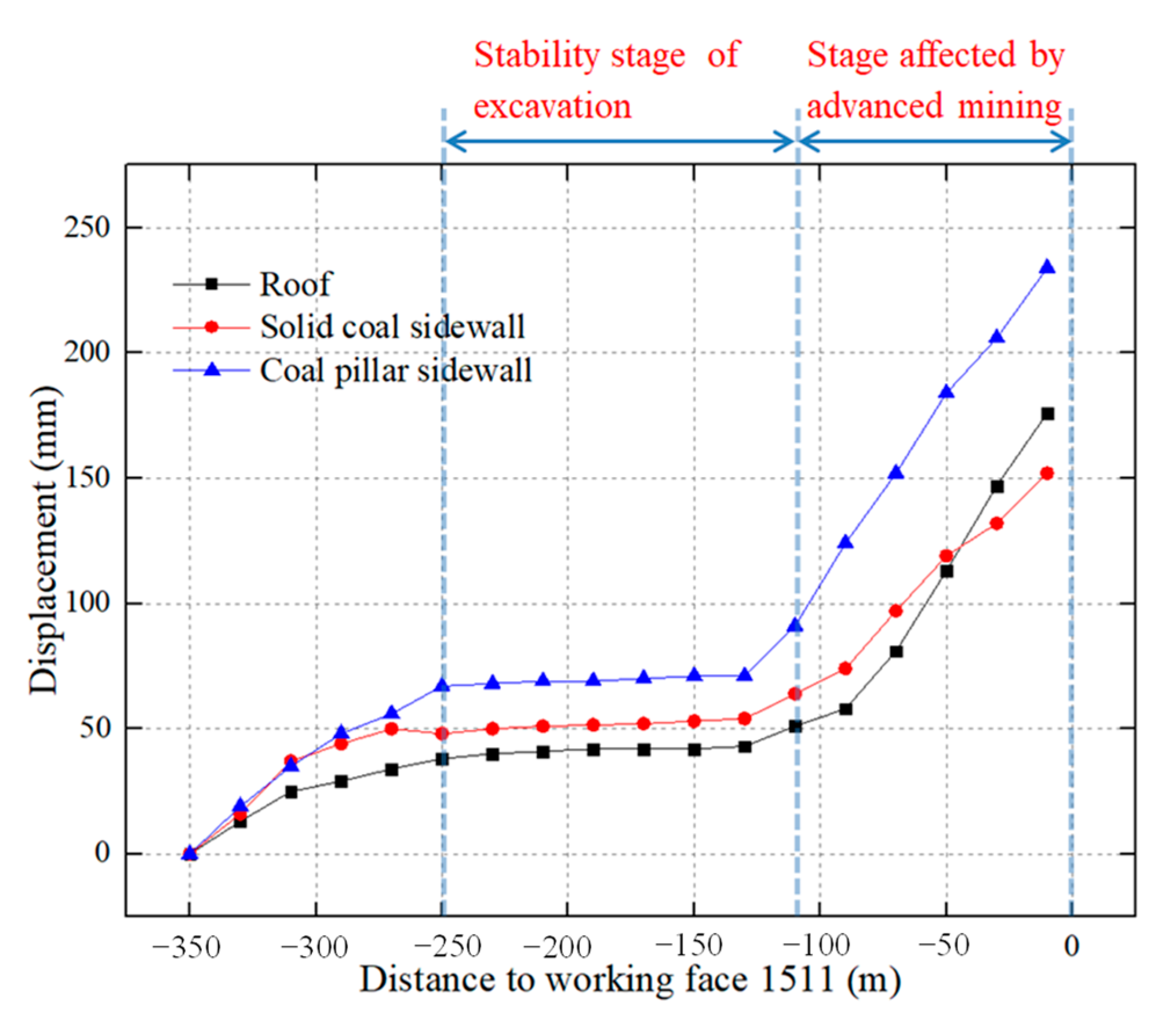
(1) The displacement of roadway roof and two sides all show three stages (Figure 11). The first stage was the slow growth stage of displacement, which was also the excavation disturbance stage; the second stage was the displacement stability stage, which was the stability stage after excavation disturbance; the third stage was the accelerated growth stage of displacement, which was affected by the advanced mining of working face 1511.
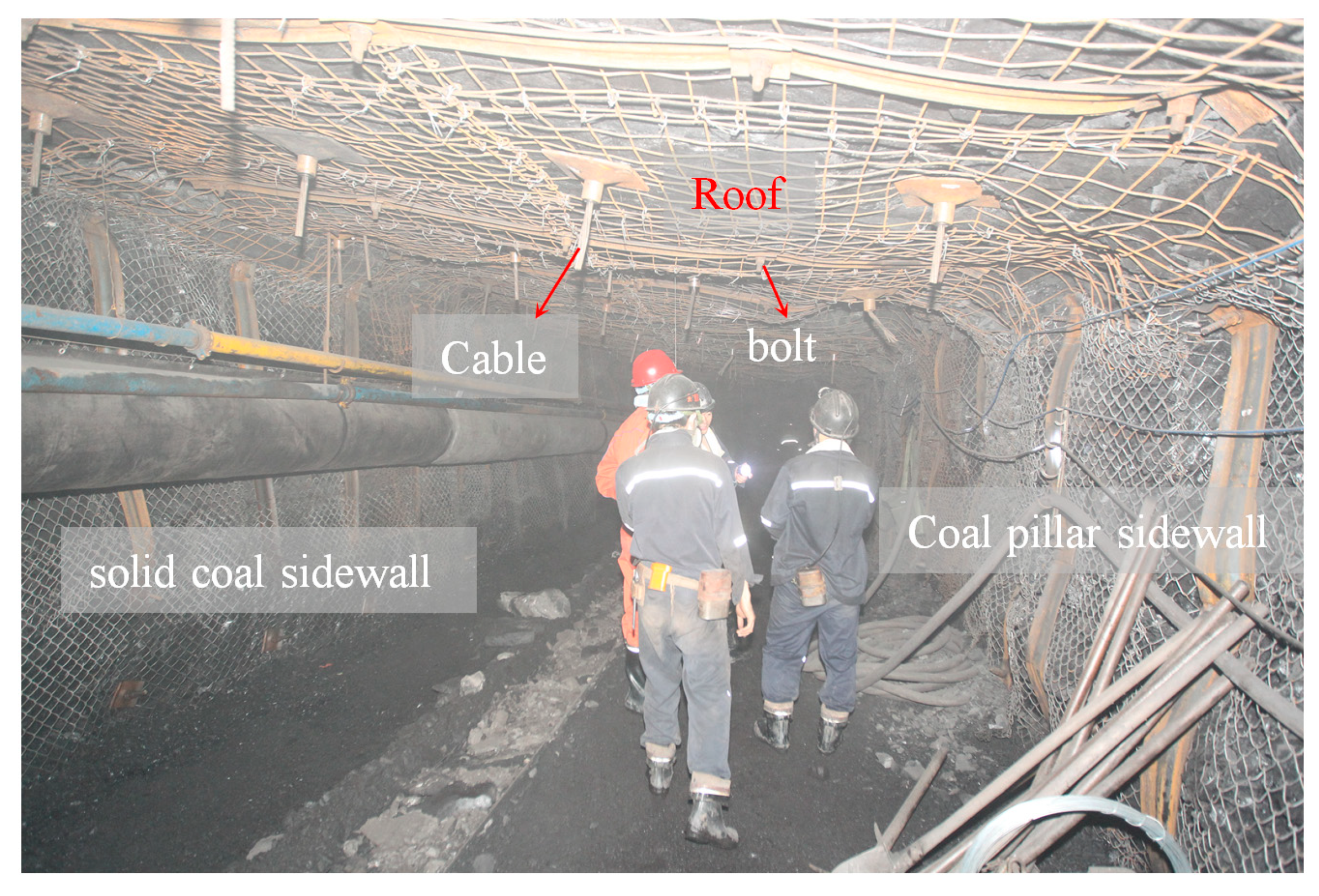
(2) After the stability of first and second stage, the displacement of roof, solid coal side, and coal pillar side were 43 mm, 54 mm, and 72 mm, respectively. The small displacement and the flat surrounding rock (Figure 12) indicated that the excavation disturbance had little impact on the stability of the surrounding rock of the roadway.
(3) In the third stage, the distance between the roadway excavating working face and working face 1511 was in the range of 0~110 m, and the maximum displacement of the roof, the solid coal side, and the coal pillar side were 176 mm, 152 mm, and 234 mm, respectively. It was concluded that the advanced influence distance of working face 1511 on MTR 1513 was 110 m.

5.1.2. Control Effects Analysis of Zone B

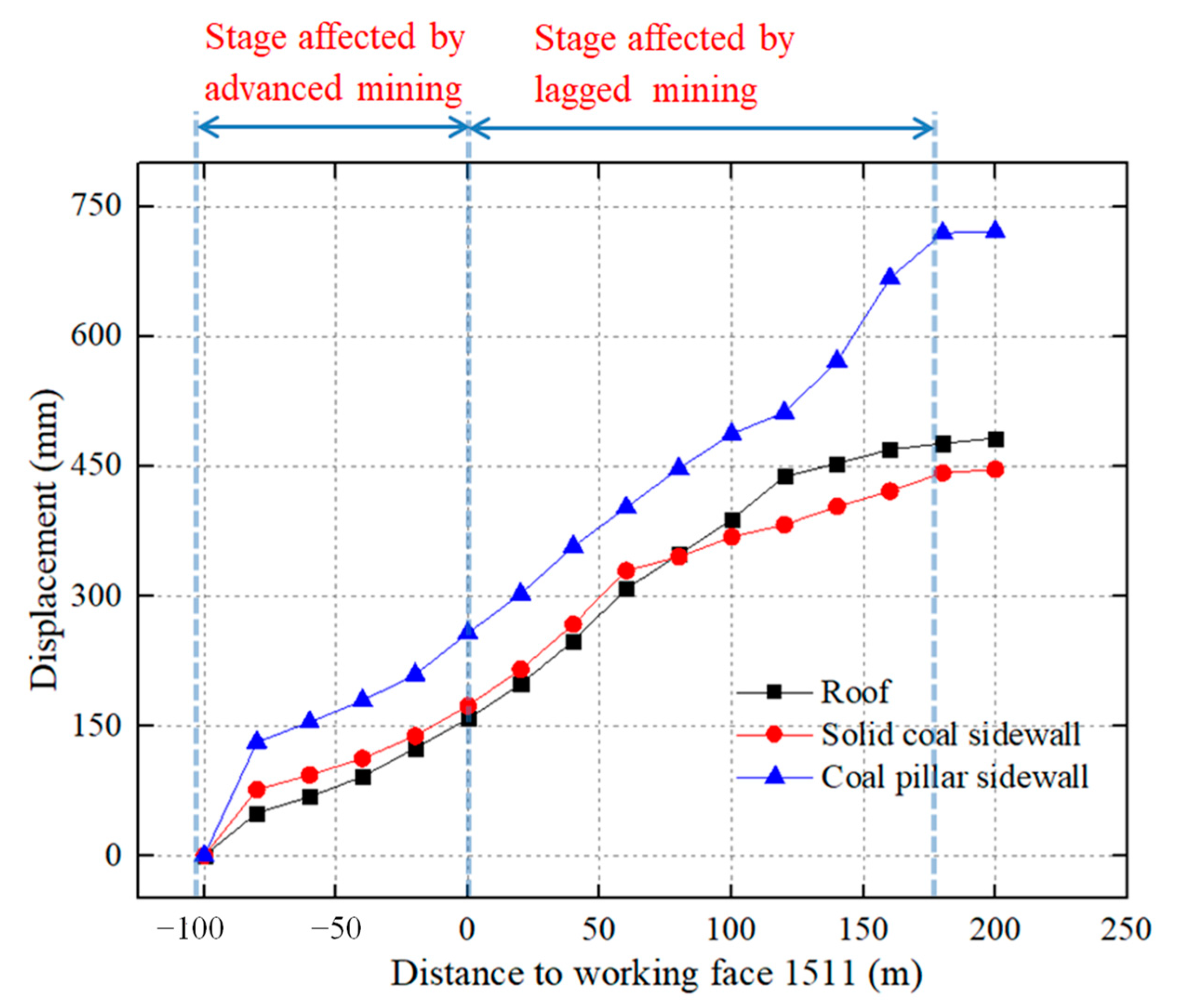
(1) The displacement of roadway roof and two sides also show three stages (Figure 13). The first stage was sustained displacement growth (−100 m~0 m), the second stage was accelerated displacement growth (0~175 m), and the third stage was stable displacement stage (beyond 175 m).
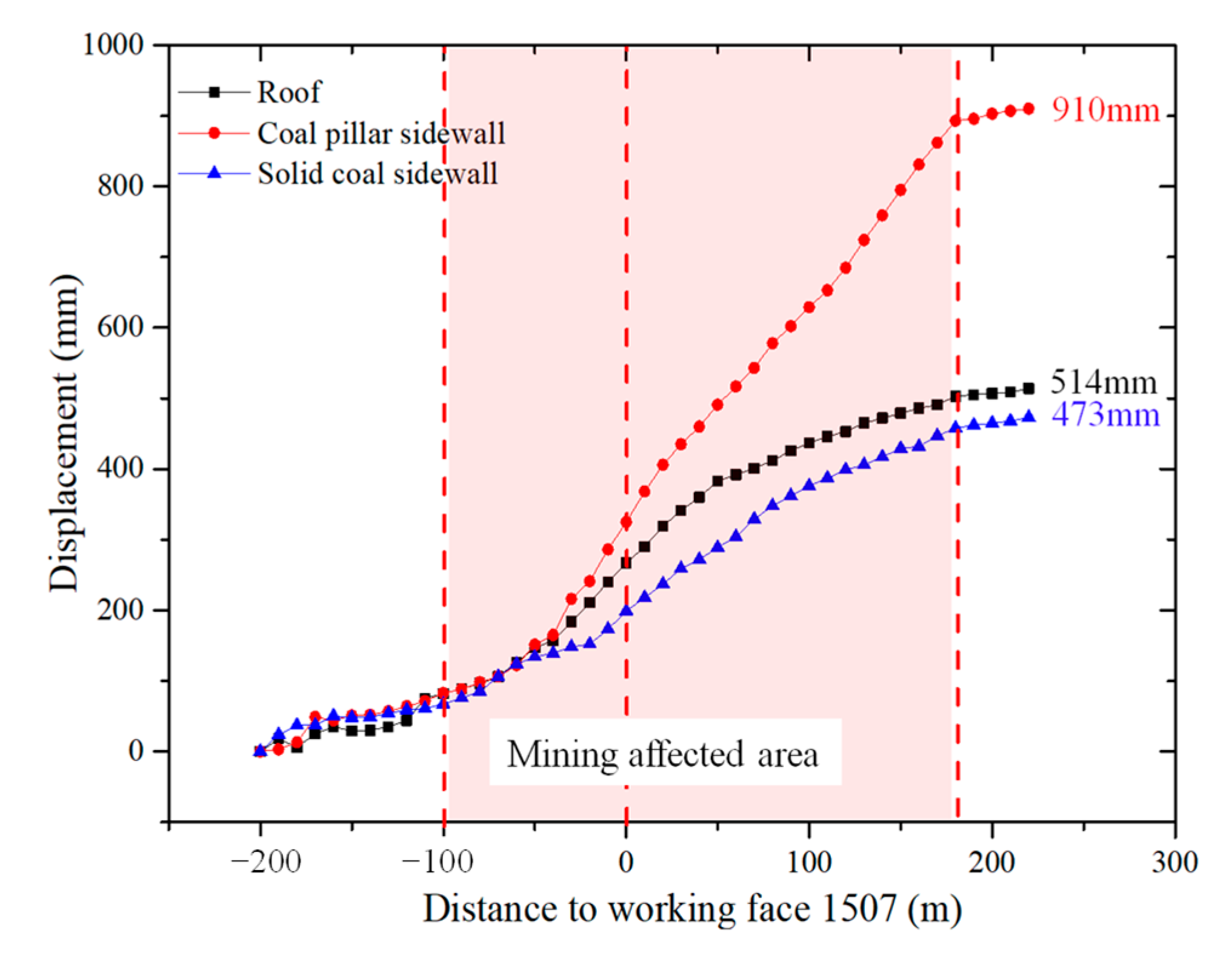
(2) The first stage was the advanced mining influence stage of working face 1511. In this stage, the displacement of roadway surrounding rock continued to increase under the influence of advanced mining, and the maximum displacement of roof, solid coal side, and coal pillar side were 187 mm, 172 mm, and 264 mm, respectively.
(3) The second stage was the delayed mining influence stage of working face1511. Compared with the first stage, the surrounding rock of roadway in this stage was strongly affected by the delayed mining of working face 1511. Therefore, the displacement rate of surrounding rock had a slight increase trend.
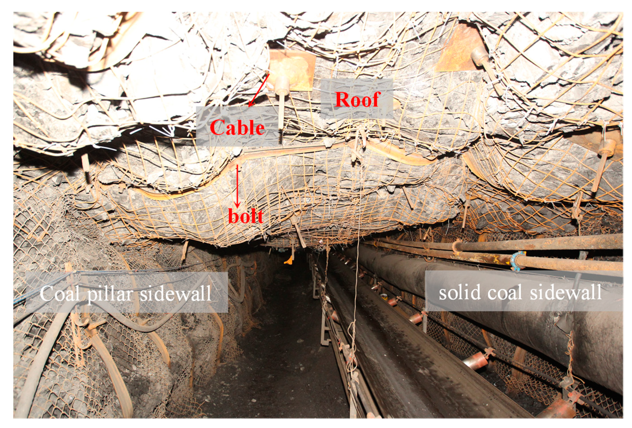
In the second stage, the maximum displacement of roadway roof, solid coal side, and coal pillar side were 463 mm, 427 mm, and 707 mm, respectively. The roadway surrounding rock suffers great deformation (Figure 14) with obvious roof subsidence, and the coal pillar wall was greatly displaced, indicating that working face 1511 had caused a strong delayed mining impact on MTR 1513. However, compared with the maximum displacement of ATR 1511, the deformation control effect of roadway surrounding rock at this stage was significantly improved.
(4) In the third stage, MTR 1513 was located outside 175 m behind mining face 1511. During this stage, the delayed mining effect of working face 1511 tends to be stable, and so was the deformation of surrounding rock of roadway, which no longer increased significantly.

5.1.3. Control Effects Analysis of Zone C

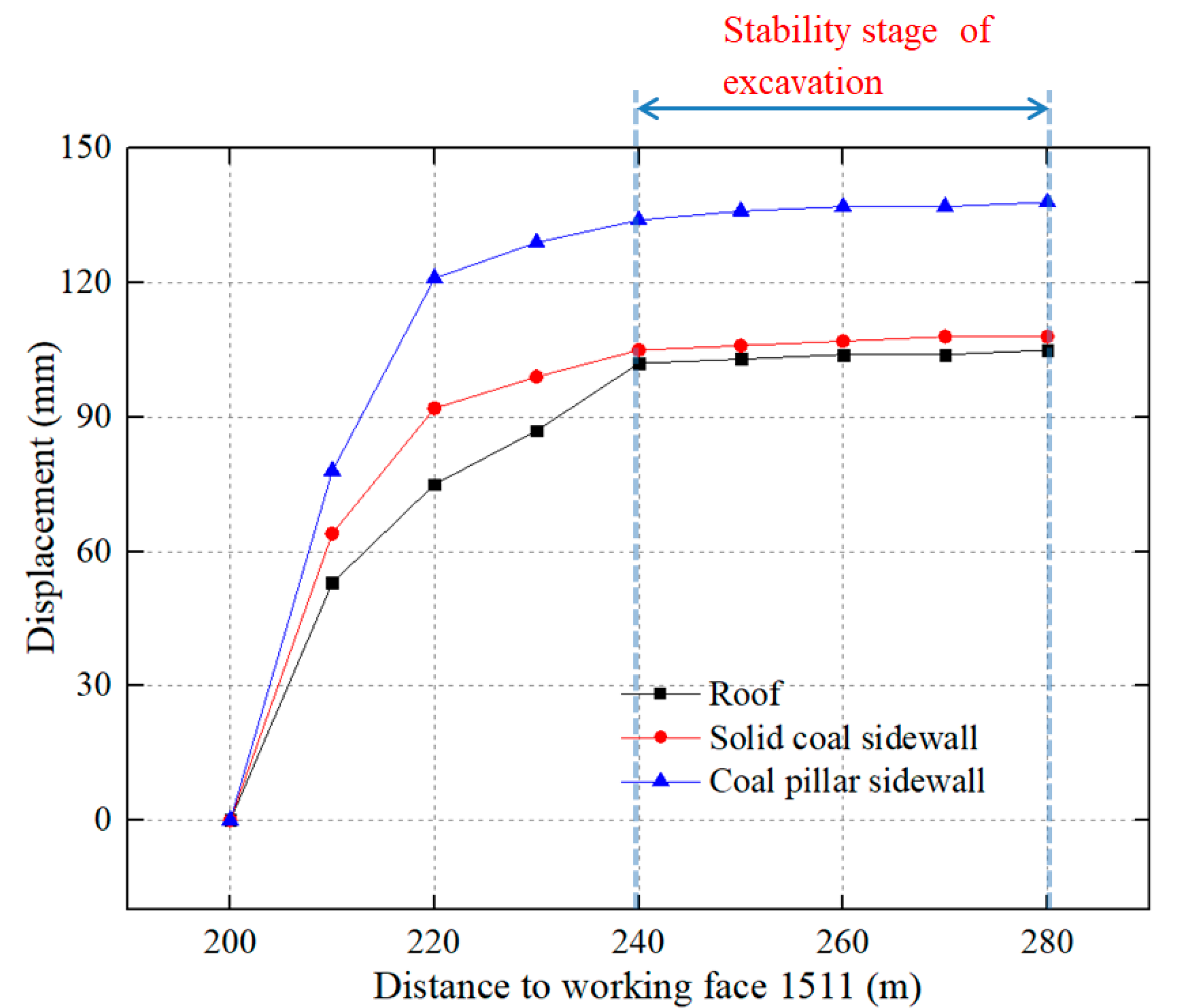
Since the roadway section in Zone C was far away from the delayed mining influence range of adjacent working face 1511 during excavation, the displacement changes of roadway roof and two sides show two stages (Figure 15). The deformation law in Zone C was consistent with the first and second stage of Zone A. The first stage was the excavation dynamic pressure disturbance stage after the roadway was excavated, and the second stage was the stability stage after the excavation dynamic pressure disturbance. The displacement of the stabilized roof, solid coal side, and coal pillar side were 105 mm, 108 mm, and 138 mm, respectively, which showed good control effect (Figure 16).

5.2. Discussion

From the deformation law of the three zones of MTR 1513, the mining influence range of adjacent working face 1511 on roadway surrounding rock ranged from 110 m advanced to 175 m delayed, which was close to the mining influence range of the previous analysis.
For Zone A, the maximum displacement of roadway roof, solid coal side, and coal pillar side were 43 mm, 54 mm, and 72 mm, respectively, before being influenced by advanced mining, which indicated that the anchorage support technology proposed in this paper shows good adaptability to control of surrounding rock during the excavation of such roadways. After being influenced by advanced mining of working face 1511, the maximum displacement of roof, solid coal side, and coal pillar side were 176 mm, 152 mm, and 234 mm, respectively. At this time, the displacement of surrounding rock was effectively controlled. It can be concluded that the adopted control technology scheme of first anchoring and then relieving pressure can adapt well to the stress fluctuation caused by advanced mining, as well as maintain the stability of roadway surrounding rock.
For Zone B, after the transition from the influence of advanced mining to the delayed mining in working face 1511, the deformation of surrounding rock increased, indicating that the influence of working face 1511 mining on the delayed mining of MTR 1513 was stronger than that of advanced mining, and previous analysis was also verified. After experiencing the influence of strong mining in advanced and delayed stages, the surrounding rock of the roadway was greatly deformed. However, the control effect was still obviously improved, showing that the pressure relief anchorage synchronous cooperative control technology can significantly alleviate mining stress and effectively anchor the surrounding rock.
For Zone C, the coal and rock masses in the early stage were affected by the advanced and delayed stages of adjacent 1511 working face before excavating, so the coal and rock masses were broken. Compared with Zone A, which escaped the influence of advanced mining of working face 1511, the surrounding rock deformation of Zone C was larger, but the overall control effect of roadway surrounding rock was better (Figure 16).
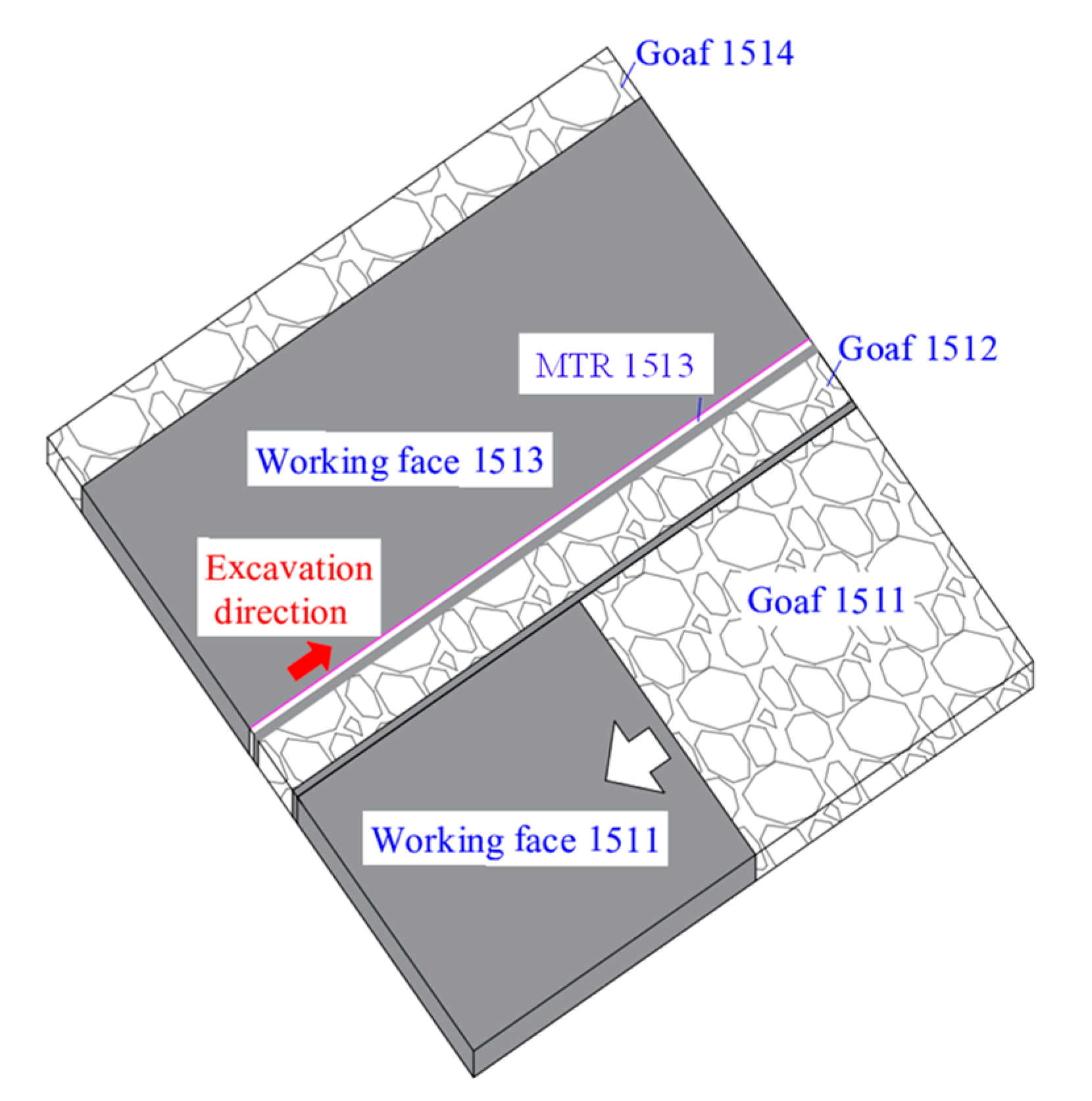
Even if goaf 1512 were located between working face 1511 and MTR 1513, the mining of the 1511 working face will still have a strong mining impact on the MTR 1513 due to the small width of goaf 1512, resulting in a given large deformation of the surrounding rock. According to the influence range of mining, the technology of corresponding synchronous coordination of pressure relief and anchoring were proposed in different zones, which can effectively relieve pressure and anchor the surrounding rock within the small structure range of gob-side roadway with good control effects.

6. Conclusions

Based on the rare typical engineering case of gob-side roadway driving with small coal-pillar facing mining in isolated island working face under alternate mining of wide and narrow working faces, this paper studies and finds the characteristics of zoning differential distribution of surrounding rock stress and deformation of the gob-side roadway driving with small coal pillar facing mining in the special isolated island working face. Based on this, the roadway was divided into several zones, for different zones, the zoning control cooperative control technology of pressure relief and anchorage was proposed, and an industrial test was carried out. From these studies, the following conclusions were drawn:
(1) Under the influence of strong mining in adjacent working faces, gob-side roadway driving with small coal-pillar facing mining in isolated island working face suffers from great deformation. The variation law of displacement was divided into two stages, namely, the advanced influence stage of working face (within the range of 100 m ahead) and the delayed influence stage of working face (within the range of 180 m behind). When the roadway surrounding rock was in the delayed influence stage, the disturbance influence on surrounding rock in this stage was stronger than that in advanced stage as the result of broken and rotation of high-level rock stratum isolated island.
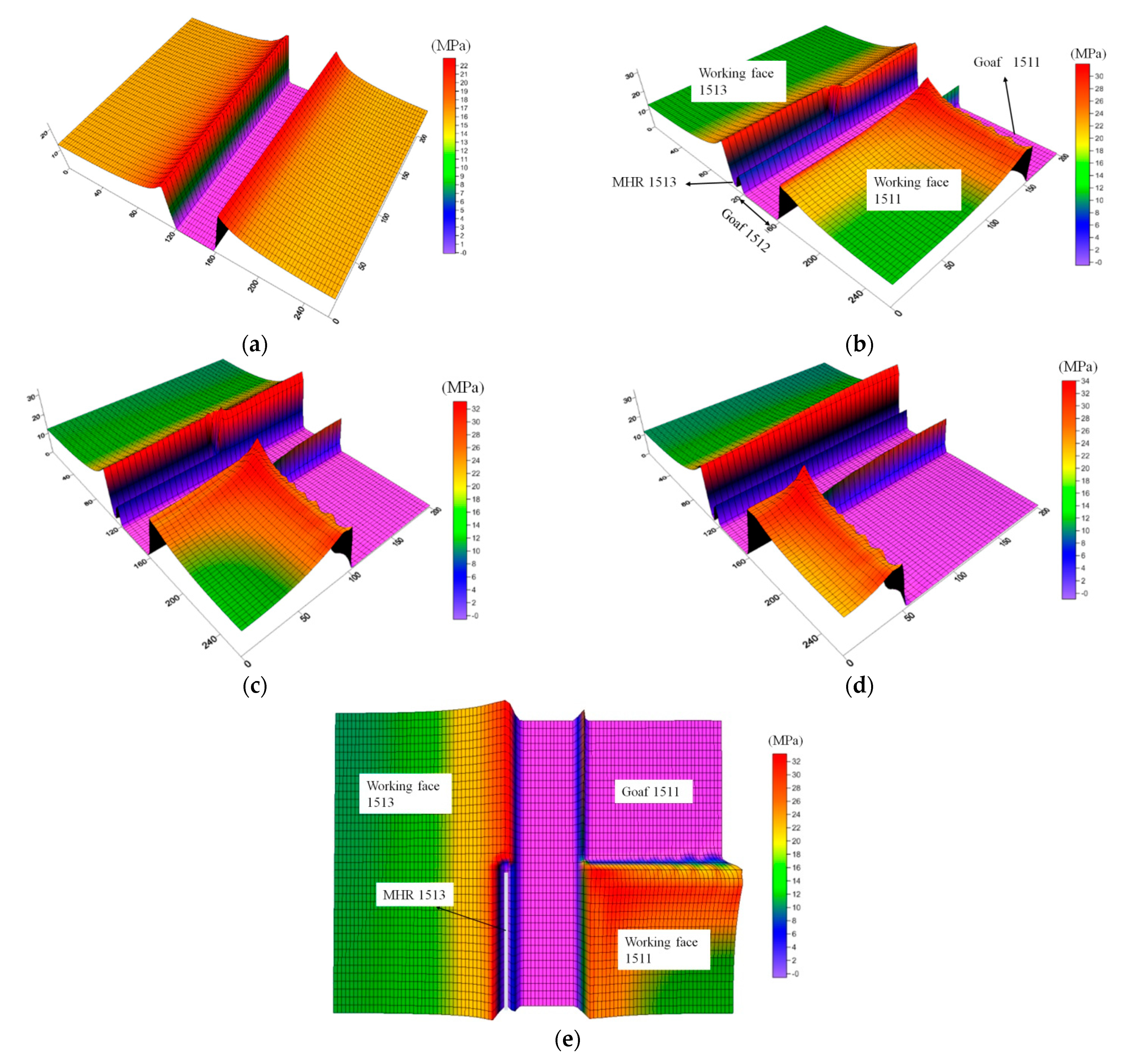
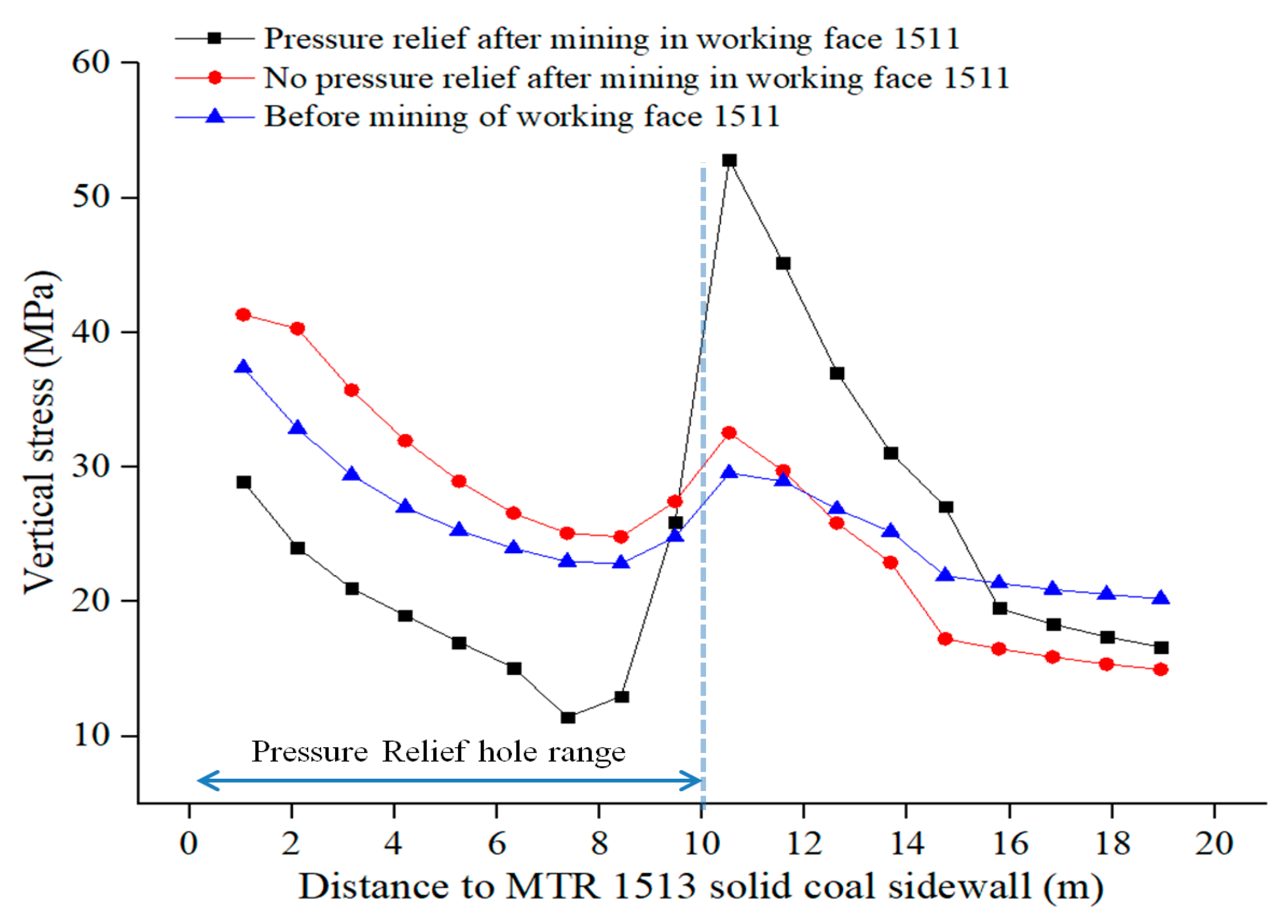
(2) According to the stress evolution law and numerical simulation results of gob-side roadway driving under face mining, during the excavating of MTR 1513, the stress concentration in the excavating face was obvious due to the influence of the advanced support stress of working face 1511. When the excavating face was located behind the working face 1511, the stress concentration of roadway surrounding rock was further strengthened due to the influence of delayed mining stress, which verified the two disturbed stages of roadway surrounding rock displacement change.
(3) Based on the zoning deformation characteristics and stress evolution law of surrounding rock of gob-side roadway driving with small coal pillar under face mining, the MTR 1513 was divided into three zones. The first zone was heading face mining zone, which would not be affected by mining during roadway excavation, but would be affected by advanced mining of working face 1511 later. The second zone was the mining influenced zone, which would be affected by the advanced and delayed mining influence of working face 1511 during roadway excavation; the third zone was the mining stability zone, that is, during roadway excavation, the mining influence has tended to be stable and will no longer be affected by the disturbance of mining stress.
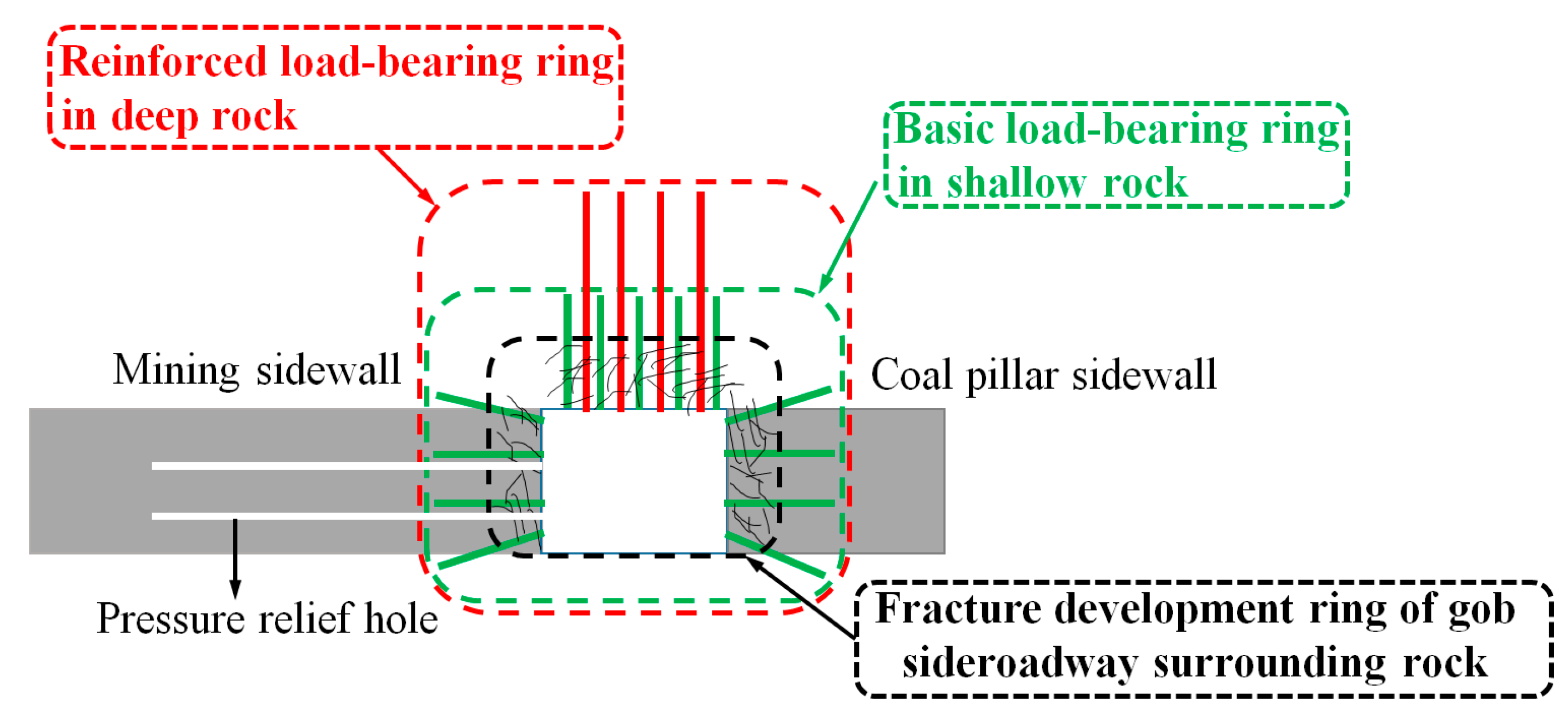
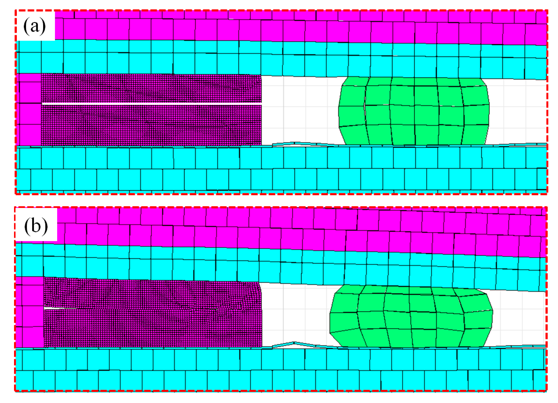
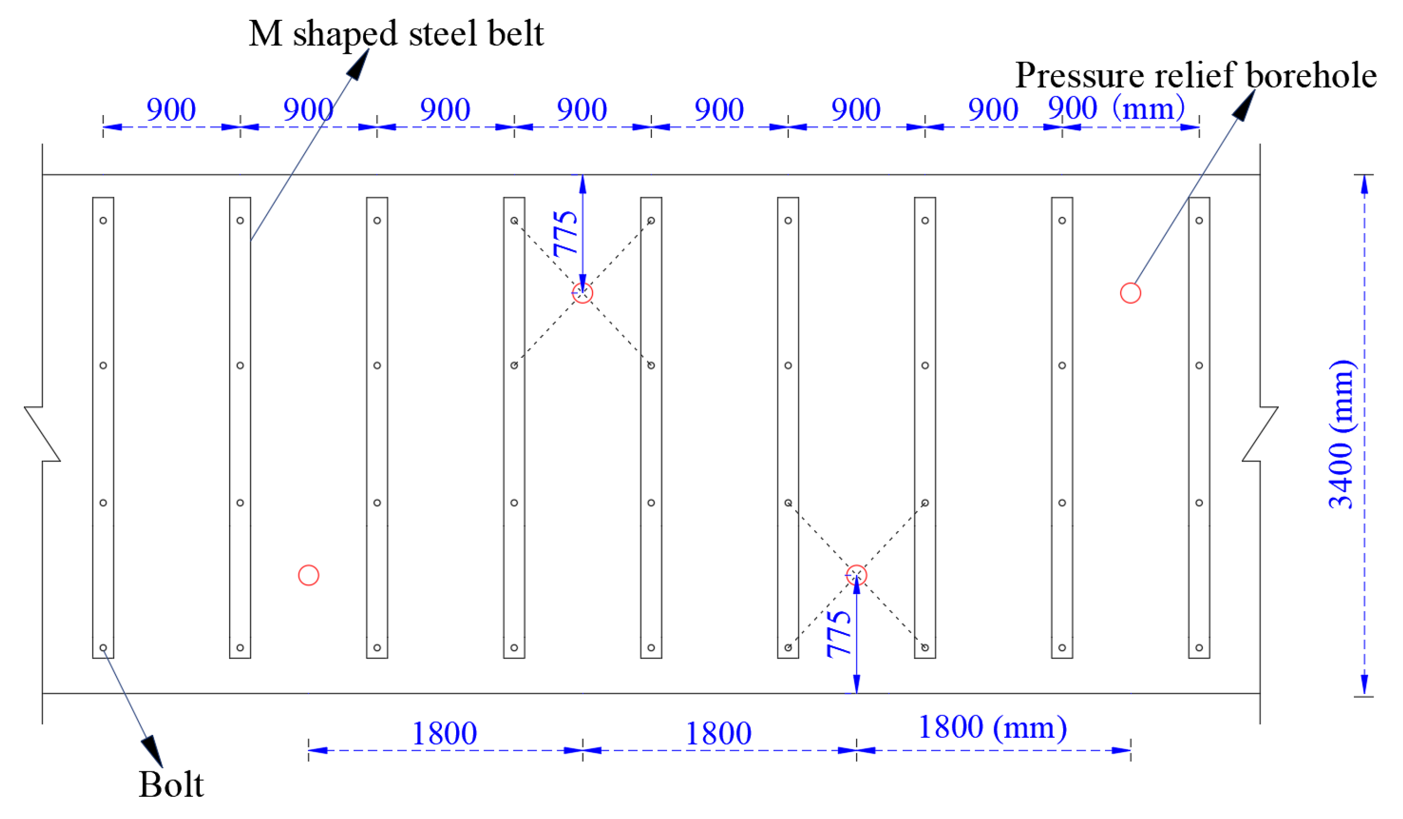
(4) The targeted cooperative control technology of pressure relief and anchorage was proposed, and the pressure relief effect was verified by numerical simulation method. Targeted control methods were put forward for the three zones of MTR 1513, and the differentiated control technology were formed. For the heading face mining zone (Zone A), the control method of anchoring first and then relieving pressure was adopted. For the mining influenced zone (Zone B), the control method of simultaneous cooperation of pressure relief and anchorage was adopted. For the mining stability zone (Zone C), the control method of anchoring, without pressure relief, was adopted.
(5) Engineering practice shows that the disturbance influence distance of working face 1511 on MTR 1513 ranges from 110 m ahead to 175 m behind. After being affected by advanced mining, the maximum displacement of roof, solid coal side, and pillar side in Zone A were 176 mm, 152 mm, and 234 mm, respectively, with good control effect. After being affected by two stages of mining stress, large deformation of surrounding rock occurs in Zone B, but the control effect was still obviously improved. The coal and rock mass in Zone C was loose and broken after mining, but the control effect on overall deformation was good. The results and analysis presented here verify the division rationality of the three zones and the feasibility of the zoning control technology scheme, avoiding using only one control technology to solve the stability control problem in different areas of the roadway.

Author Contributions

Data curation, C.H.; formal analysis, H.Y., C.H. and N.Z.; funding acquisition, C.H.; investigation, C.H. and H.Y.; project administration, C.H. and N.Z.; writing—original draft preparation—C.H. and H.Y.; writing—review and editing, H.Y., C.H., R.D. and Y.G. All authors have read and agreed to the published version of the manuscript.

Funding

This work was supported by the Fundamental Research Funds for the Central Universities (2019QNA23).

Institutional Review Board Statement

Not applicable.

Informed Consent Statement

Not applicable.

Data Availability Statement

Data is contained within the article.

Acknowledgments

The authors are very grateful to the reviewers for carefully reading the manuscript and providing valuable suggestions.

Conflicts of Interest

The authors declare no conflict of interest.

Abbreviations

MTR 1513main haulage roadway 1513
ATR 1511auxiliary transportation roadway 1511

References

  1. Zhang, S.; Wang, X.F.; Fan, G.W.; Zhang, D.S.; Cui, J.B. Pillar size optimization design of isolated island panel gob-side entry driving in deep inclined coal seam—Case study of Pingmei No. 6 coal seam. J. Geophys. Eng. 2018, 15, 816–828. [Google Scholar] [CrossRef] [Green Version]
  2. Schumacher, F.P.; Kim, E. Modeling the pipe umbrella roof support system in a Western US underground coal mine. Int. J. Rock Mech. Min. 2013, 60, 114–124. [Google Scholar] [CrossRef]
  3. Coggan, J.; Gao, F.; Stead, D.; Elmo, D. Numerical modelling of the effects of weak immediate roof lithology on coal mine roadway stability. Int. J. Coal Geol. 2012, 90, 100–109. [Google Scholar] [CrossRef]
  4. Dou, L.M.; He, H. Study of OX-FT spatial structure evolution of overlying strata in coal mines. Chin. J. Rock Mech. Eng. 2012, 31, 453–460. [Google Scholar]
  5. Jiang, F.X.; Cheng, G.; Feng, Y.; Wang, C.W.; Xu, Y.Y. Research on coal overall instability of isolated working face with irregular gobs on both sides. Chin. J. Rock Mech. Eng. 2015, 34 (Suppl. 2), 4164–4170. [Google Scholar]
  6. Cao, A.Y.; Zhu, L.L.; Li, F.C.; Dou, L.M.; Zhao, Y.L.; Zhang, Z.L. Characteristics of T-type overburden structure and tremor activity in isolated face mining under thick-hard strata. J. China Coal Soc. 2014, 39, 328–335. [Google Scholar]
  7. Zhang, W.; Zhang, D.S.; Chen, J.B.; Xu, M.T. Control of sorrounding rock deformation for bob-side ebtry driving in narrow coal pillar of island coalface. J. China Univ. Min. Technol. 2014, 43, 36–42. [Google Scholar]
  8. Bai, J.B.; Shen, W.L.; Guo, G.L.; Wang, X.Y.; Yu, Y. Roof deformation, failure characteristics, and preventive techniques of gob-side entry driving heading adjacent to the advancing working face. Rock Mech. Rock Eng. 2015, 48, 2447–2458. [Google Scholar] [CrossRef]
  9. Ma, D.P.; Wang, T.X.; Liu, Y. An analysis of “space-time” relationship of gob-side entry driving in dynamic pressure area. J. Min. Saf. Eng. 2015, 32, 465–470. [Google Scholar]
  10. Zhang, Y.; Wan, J.Z.; Li, F.C.; Zhou, C.B.; Zhang, B.; Guo, F.; Zhu, C.T. Stability of coal pillar in gob-side entry driving under unstable overlying strata and its coupling support control technique. Int. J. Min. Sci. Technol. 2013, 23, 204–210. [Google Scholar] [CrossRef]
  11. Yin, Q.; Jing, H.W.; Dai, D.P.; Zhu, T.T.; Zhao, H.H.; Meng, B. Cable-truss supporting system for gob-side entry driving in deep mine and its application. Int. J. Min. Sci. Technol. 2016, 26, 885–893. [Google Scholar] [CrossRef]
  12. Yang, J.P.; Cao, S.G.; Li, X.H. Failure laws of narrow pillar and asymmetric control technique of gob-side entry driving in island coal face. Int. J. Min. Sci. Technol. 2013, 23, 271–276. [Google Scholar] [CrossRef]
  13. Li, X.H.; Ju, M.H.; Yao, Q.L.; Zhou, J.; Chong, Z.H. Numerical investigation of the effect of the location of critical rock block fracture on crack evolution in a gob-side filling wall. Rock Mech. Rock Eng. 2016, 49, 1041–1058. [Google Scholar] [CrossRef]
  14. He, F.L.; Chen, J.Y.; Zou, X.Z.; Qu, Q.D.; Liang, Y.; Ling, B.C.; Yang, Y.M. Study on depressurizing control of the surrounding rock of a roadway along gob area in sub-level caving mining. J. China Coal Soc. 2000, 25, 589–592. [Google Scholar]
  15. Li, D.P.; Dou, L.M.; Mou, Z.L.; Guo, X.Q.; Liu, L.P. The anti-arc overlying strata structure induced mechanism and control of isolated corner coal pillar working face. J. China Coal Soc. 2012, 37, 719–724. [Google Scholar]
  16. Yang, H.Q.; Han, C.L.; Zhang, N.; Sun, C.L.; Pan, D.J.; Dong, M.H. Stability Control of a Goaf-Side Roadway under the Mining Disturbance of an Adjacent Coal Working Face in an Underground Mine. Sustainability 2019, 11, 6398. [Google Scholar] [CrossRef] [Green Version]
  17. Geng, H. Study on the Stability Control Technology of Surrounding Rock for Gob-Side Entry Driving foward the Mining Face Separate by a Narrow Goaf. Master’s Thesis, China University of Mining and Technology, Xuzhou, China, 2019. [Google Scholar]
  18. Xie, Z.Z.; Zhang, N.; Feng, X.W.; Liang, D.X.; Wei, Q.; Weng, M.Y. Investigation on the evolution and control of surrounding rock fracture under different supporting conditions in deep roadway during excavation period. Int. J. Rock Mech. Min. Sci. 2019, 123, 104122. [Google Scholar] [CrossRef]
  19. Yang, H.Q.; Han, C.L.; Zhang, N.; Sun, Y.T.; Pan, D.J.; Sun, C.L. Long High-Performance Sustainable Bolt Technology for the Deep Coal Roadway Roof: A Case Study. Sustainability 2020, 12, 1375. [Google Scholar] [CrossRef] [Green Version]
  20. Xie, Z.Z.; Zhang, N.; Han, C.L.; An, Y.P. Research on principle and application of roof thick layer cross-boundary anchorage in coal roadways. Chin. J. Rock Mech. Eng. 2021, 40, 1195–1208. [Google Scholar]
  21. Han, C.L.; Zhang, N.; Kan, J.G.; Ran, Z. Mechanism and application of double active control with pressure-relieving and anchoring for gob-side entry retaining. J. China Coal Soc. 2017, 42 (Suppl. 2), 323–330. [Google Scholar]
  22. Yang, H.Q.; Zhang, N.; Han, C.L.; Sun, C.L.; Song, G.H.; Sun, Y.T.; Sun, K. Stability Control of Deep Coal Roadway under the Pressure Relief Effect of Adjacent Roadway with Large Deformation: A Case Study. Sustainability 2021, 13, 4412. [Google Scholar] [CrossRef]
Figure 1. Roadway layout and mining environment.
Applsci 11 10744 g001
Figure 2. Surrounding rock deformation characteristics of ATR 1511 under mining disturbance of the adjacent working face.
Applsci 11 10744 g002
Figure 3. Numerical calculation model: (a) 3D model; (b) schematic diagram of plane model.
Applsci 11 10744 g003
Figure 4. Stress evolution characteristics of gob-side roadway driving under face mining: (a) mining working face 1512, then forming a goaf with a width of 40 m; (b) excavating 100 m of roadway, mining 50 m of working face 1511; (c) excavating 100 m of roadway, mining 100 m of working face 1511; (d) excavating 200 m of roadway, mining 150 m of working face 1511; (e) prone view of (c).
Applsci 11 10744 g004
Figure 5. Result of zone division on MTR 1513.
Applsci 11 10744 g005
Figure 6. Collaborative control technology of pressure relief and anchorage.
Applsci 11 10744 g006
Figure 7. Comparison of vertical stress of solid coal side roof of MTR 1513 before and after pressure relief.
Applsci 11 10744 g007
Figure 8. Deformation of the pressure relief hole before and after mining in working face 1511. (a) before the mining of working face 1511; (b) after the mining of working face 1511.
Applsci 11 10744 g008
Figure 9. Supporting technical scheme.
Applsci 11 10744 g009
Figure 10. Pressure relief drilling parameters of solid coal side.
Applsci 11 10744 g010
Figure 11. Surface displacement law of surrounding rock in zone A of MTR 1513.
Applsci 11 10744 g011
Figure 12. Photos of zone A in MTR 1513.
Applsci 11 10744 g012
Figure 13. Surface displacement law of surrounding rock in zone B of MTR 1513.
Applsci 11 10744 g013
Figure 14. Photos of zone B in MTR 1513.
Applsci 11 10744 g014
Figure 15. Surface displacement law of surrounding rock in zone C of MTR 1513.
Applsci 11 10744 g015
Figure 16. Photos of zone C in MTR 1513.
Applsci 11 10744 g016
Table 1. Numerical simulation of rock stratum and lithology parameters.
NumberLithologic CharactersThickness/mBulk Density (kg/m³)Bulk Modulus/GPaShear Modulus/GPaLinternal Friction Angle/°Cohesion/MPa
9overburden13.725008.36.4332.7
8siltstone16.4270010.47.7363.2
7fine sandstone1.526005.94.1301.8
6siltstone5.3270010.47.7363.2
5coal0.314001.40.6240.7
4siltstone3.4270010.47.7363.2
3fine sandstone3.626005.94.1301.8
2siltstone1.0270010.47.7363.2
1carbonaceous siltstone0.623004.42.6281.1
03up coal3.114001.40.6240.7
−1siltstone3.1270010.47.7363.2
−2fine sandstone28.026005.94.1301.8
Publisher’s Note: MDPI stays neutral with regard to jurisdictional claims in published maps and institutional affiliations.

