Article

An Integrative Experimental Approach to Design Optimization and Removal Strategies of Supporting Structures Used during L-PBF of SS316L Aortic Stents

1
Ostbayerische Technische Hochschule Regensburg, Galgenbergstrasse 30, 93053 Regensburg, Germany
2
Technologie Campus Parsberg-Lupburg, Am Campus 1, 92331 Parsberg, Germany
3
FIT AG, Am Grohberg 1, 92331 Lupburg, Germany
*
Author to whom correspondence should be addressed.
Appl. Sci. 2021, 11(19), 9176; https://doi.org/10.3390/app11199176
Submission received: 2 September 2021 / Revised: 28 September 2021 / Accepted: 29 September 2021 / Published: 2 October 2021
(This article belongs to the Special Issue Additive Manufacturing and System: From Methods to Applications)

Abstract

:

Featured Application

The work presented in this manuscript is part of the preliminary investigations to optimize the patient-specific manufacturing of aortic stents using laser powder bed fusion (L-PBF) additive manufacturing (AM). The filigree structure of stents requires the use of support structures for their manufacture. An optimal structural design was identified and the influence of three post-processing strategies on the removal of supporting structures was investigated.

Abstract

One of the fundamental challenges in L-PBF of filigree geometries, such as aortic stents used in biomedical applications, is the requirement for a robust yet easily removable support structure that allows each component to be successfully fabricated without distortion. To solve this challenge, an integrative experimental approach was attempted in the present study by identifying an optimal support structure design and an optimized support removal strategy for this design. The specimens were manufactured using four different support structure designs based on the geometry exposed to the laser beam during the L-PBF. Support removal procedures included sand blasting (SB), glass bead blasting (GB), and electrochemical polishing (ECP). The two best-performing designs (line and cross) were chosen due to shorter lead times and lower material consumption. As an additional factor that indicates a stable design, the breaking load requirement to remove the support structures was determined. A modified line support with a 145° included angle was shown to be the best support structure design in terms of breaking load, material consumption, and manufacturing time. All three procedures were used to ensure residue-free support removal for this modified line support design, with ECP proving to be the most effective.

1. Introduction

Manufacturing filigree components in near-net form with high precision is a difficult engineering undertaking. Traditional manufacturing methods typically include subtractive procedures such as milling, which wastes a lot of material, or precision casting (lost wax method), which takes a long time and costs a lot of money [1,2]. AM methods, which were first introduced as a tool for the rapid prototyping of industrial components, have acquired substantial traction in recent years for commercial fabrication [3,4,5]. When adopting AM technologies for the small-volume manufacturing of filigree components, the fundamental principle of three-dimensional component manufacturing using an input CAD model enables great design freedom [6]. Furthermore, employing AM technologies, customized manufacturing can be done in a relatively short amount of time while still meeting the specifications of the finished product.
L-PBF is a potential AM approach for achieving near-net shaping of components by depositing a powder layer of a certain thickness and then utilizing a laser source to fuse selective regions within the powder bed according to slices defined by an input 3D model. When compared to other AM processes such as wire arc additive manufacturing (WAAM) [7,8], L-PBF is by far one of the most dependable AM routes for fabricating complicated geometry components with surface roughness dictated by powder particle size, resulting in less post-processing. The L-PBF process has also resulted in mechanical properties that are superior to casting [9]. Nonetheless, the repeated melting and solidification during the L-PBF process, as well as the associated residual stress generation, could result in delamination during manufacturing or distortion after removal from the support plate [10]. The design freedom available when employing L-PBF AM to fabricate metallic components is limited due to the inherent residual stress generation during manufacturing. Furthermore, the layer-by-layer fabrication of filigree structures can result in distinct traces in subsequent layers [11]. As a result, additional support structures are needed to manufacture filigree structures using the L-PBF method [12].
Support structures can serve a variety of purposes depending on the AM method used [11]. Support structures are critical for a product’s manufacturability, particularly when the geometry is complex, such as in filigree structures [13,14]. When there are overhanging elements, support structures are required for balancing the portion [15]. Support structures also serve as a heat sink and provide less constraint, resulting in lower residual stresses [16]. Incorporating support structures during L-PBF, on the other hand, can result in additional material, time, and energy usage. As a result, there is a cost connected with this and optimizing the support structure design based on the unique application requirement is critical. Furthermore, the included support structures must be eliminated from the finished product in the most efficient and cost-effective manner possible. Hence, support structure optimization and support removal strategies need to be considered as a union of a function that optimizes the manufacturability of a filigree structure using L-PBF. The present study used a similar integrative approach with the application domain of fabricating aortic stents utilizing L-PBF.
The aorta is the largest artery in the human body, piping oxygen-rich blood to all areas of the body. The pressure at which blood flows through the aorta can damage its wall over time, resulting in enlargement and bulging [17,18]. An extra material, in the form of a metal skeleton within a fabric graft known as a stent, is implanted in the expanded area to keep the channel open for blood flow [19,20]. The use of a patient’s diagnostic history to customize the intricate metallic structure of a stent is a promising technique to improve clinical success [21]. As a result, L-PBF is a viable option for incorporating design complexity and manufacturing stents in a near-net form [22]. Support structures, on the other hand, are required to attain this goal, and their residue-free removal is a major challenge [13,14,15]. For the successful manufacturing of overhanging parts in aortic stents, it is critical to optimize the support structure design and develop cost-effective support removal procedures.
Finazzi et al. [23] established design rules for the manufacturing of cardiovascular stents employing L-PBF. As a rule, for constructing expandable stent meshes, the authors recommended avoiding the use of support structures during the stent design process since their size is similar to that of the stent struts. When support structures are integrated during design, the authors expressed concerns about the difficulty of removing them, as well as the possibility of injuring and deforming the stent during support removal. Demir et al. [22] explored the L-PBF manufacturability of CoCr alloy stents for cardiovascular applications. Instead of conventional hatching, a concentric scanning method was used to produce a prototype stent that met the design rules for the L-PBF fabrication of filigree structures. With comparable surface roughness and micro-hardness values recorded for the bulk samples, it was reported that concentric hatching increased fidelity. ECP was reported to be a suitable post-processing strategy for manufactured specimens, with varying degrees of success depending on the scan strategy. The authors concluded that the L-PBF method, when combined with ECP, can be utilized to replace micro-tube manufacturing followed by laser cutting, which is traditionally used to manufacture standard cardiovascular stents. Wessarges et al. [24] used the µ-L-PBF (L-PBF with laser beam diameter less than 40 µm) method to build stent-like structures from SS316L raw powders [25]. When appropriate laser beam parameters were chosen, high reproducibility was observed in the manufactured samples, which also had the required radial strength, acceptable elastic recoil, and good spatial resolution (60 µm). After chemical polishing, the findings revealed a part density of >99 percent and excellent surface quality. This has led to the conclusion that µ-L-PBF technology can be effectively used for the cost-effective manufacturing of complex-shaped vascular implants.
The geometry of a stent, irrespective of application, is analogous to that of a lattice structure. This allows for the adaptation of concepts from the existing literature on lattice structures, including auxetic structures, in order to improve scientific knowledge, enhance stents, and support structure designs. Bhullar et al. [26] investigated the deformation behavior of an auxetic stent with rotating square geometries manufactured by folding rigid squares and circular holes into a cylindrical shape using polyurethane sheets. The auxetic stents’ enhanced negative Poisson ratio helped them to match the properties of native blood vessel tissues, in addition to the weight savings realized by the lightweight design. Geng et al. [27] investigated the mechanical properties of chiral stents fabricated by selective laser sintering (SLS). Auxetic mechanical behavior was observed in the chiral stents proposed in their study. The authors also reported that changing the unit cell design parameters, including the strut number, ligament length, and node radius, could help to tune the appropriate auxetic behavior. To obtain the desired mechanical properties, Calleja-Ochoa et al. [28] proposed an innovative strategy of using lightweight replicative structures of various sizes and orders of magnitude. The ultralight replicative structures with a strut diameter of 100 µm demonstrated incredibly good mechanical characteristics when compared to solid materials. It is worth noting that no additional support structures were required for the successful fabrication of these replicative structures utilizing L-PBF due to the small diameters of the struts. However, due to the additional requirements of high pressure to inflate the stent post-implantation within the artery, higher mechanical properties are not normally recommended for a stent geometry. As a result, the L-PBF fabrication of aortic stents with larger strut and stent diameters necessitates the inclusion of additional support structures.
To realize the manufacturability of a filigree component like an aortic stent, the L-PBF technique includes support structures. Support structures, on the other hand, are unnecessary, and it is vital to remove them residue-free after manufacturing in order to obtain the near-net shape of final component geometry. As a result, rather than tackling the support structure design and support removal procedures individually, it is important to consider them as a single challenge. An integrative experimental approach is the best alternative to achieve a feasible solution due to the difficulties involved in combining the support structure design and support removal strategies, as well as determining the essential boundary conditions through simulation and modeling. The majority of previous support structure design optimization research was focused on topology optimization concepts or a combination of simulation and topology optimization [29,30,31]. Computer simulation was used in several of the studies to optimize the designs, which was then followed by experimental validation through manufacturing [32,33]. Experimentation is essential to confirm the appropriateness of simulated optimal support structure designs for manufacturing. This is because an optimal design must be capable of realizing a final component geometry that is as close to the input CAD model as possible. In addition, for an optimal support structure design, material utilization must be minimized and manufacturing time must be reduced. Furthermore, because support structures are an undesired part of the component, the ease with which they can be removed without leaving residue is crucial. Support structure removal strategies were rarely attempted in the past, with the majority of research focusing on improving the surface properties of L-PBF-manufactured filigree structures associated with manufacturing process design constraints [22].
Supporting structures are often viewed as a hurdle to efficiently combining design freedom and near-net-shape component manufacturing with L-PBF. As a result, the present study took an integrative experimental approach, integrating the optimization of support structure designs with the identification of an effective support removal procedure for the improved design. Three parameters were used to determine an appropriate support structure design: less material consumption, a quicker production time, and a high breaking load indicative of a stable design. In the first step, four distinct support structure designs were selected depending on the area that was exposed to the laser beam. In the next step, two of the best-performing designs were hand-picked, tested, and analyzed further. Two prominent mechanical approaches, SB and GB, were attempted as support removal procedures because of their vast utilization in actual industrial processes. The use of mechanical methods has the apparent disadvantage of adding additional strains to the component. As a result, in addition to the two mechanical routes, the performance of an electrochemical route (ECP) was also evaluated in the present study. The outcomes obtained while addressing the research problem are expected to provide a framework for the optimal manufacturing of filigree structures using the design freedom of L-PBF AM.

2. Materials and Methods
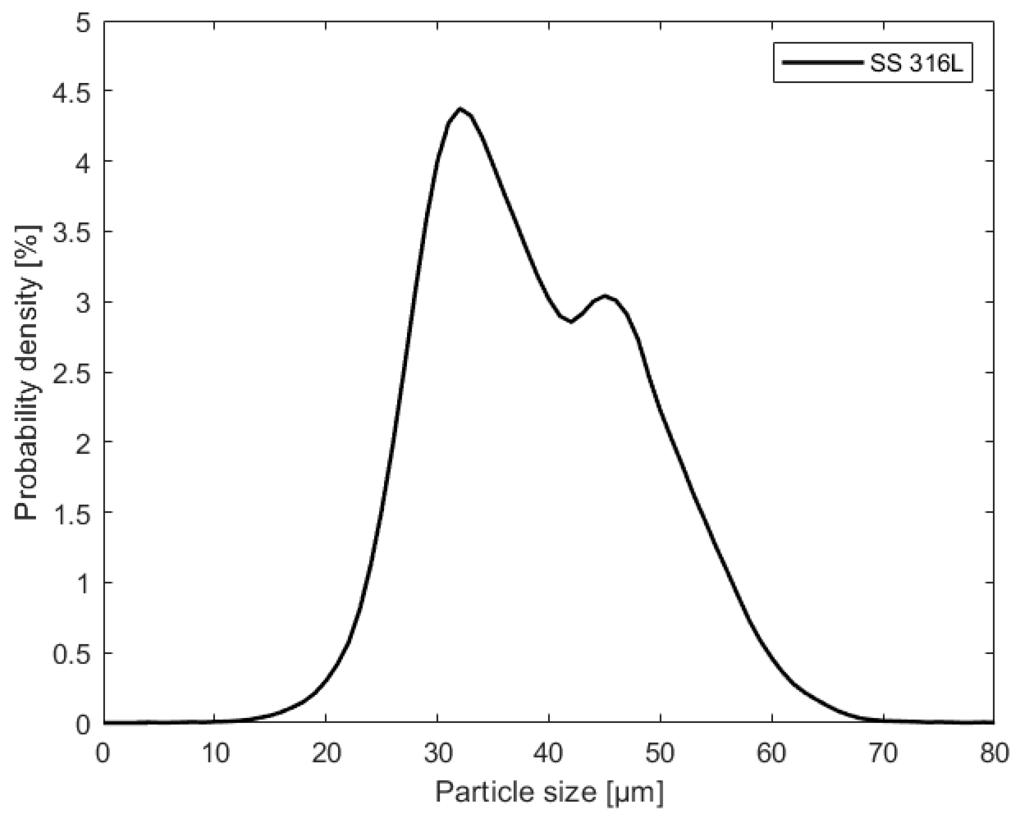
2.1. Material

An important metallic biomaterial austenitic stainless steel 316L (SS316L) was selected as the working material in the present study due to its widespread use in biomedical applications. ThyssenKrupp Materials Trading GmbH of Essen, Germany supplied the raw alloy powders of SS316L. The elemental composition of the SS316L powder provided by the supplier is given in Table 1. The support structures were manufactured from the same powder material as the specimens, but with different laser parameters. This is because obtaining full density for the support structures is less critical than manufacturing speed and ease of removal.

2.2. Methods

2.2.1. L-PBF

An SLM 250-HL L-PBF device from SLM Solutions Group AG Lübeck, Germany was used to manufacture the specimens. This L-PBF equipment allows a total build volume of 250 mm (X) × 250 mm (Y) × 280 mm (Z). A 400W Nd:YAG laser with a spot size of ~80 µm was used to fuse the powder particles. Nitrogen gas was employed as a protective atmosphere during manufacturing to avoid oxidation in the melted areas. The standard parameter set for the SS316L material available in the SLM 250-HL L-PBF system was chosen for the fabrication of specimens characterized and tested in this study. For successful fabrication of specimens, different areas were designated during the pre-processing step, and associated laser parameters were established, as shown in Table 2. The filling is the solid or core section of the specimen, which is bordered on the top and bottom by the up and down skins. The different support structure designs examined in the optimization are referred to as support. The L-PBF research has a well-established methodology for dividing into distinct manufacturing domains, as given by Table 2 [34].
The additive manufacturing of a geometry such as an aortic stent requires a significant amount of support material because each strut (basic repeating unit of the stent including its inverted counterpart) of the stent needs to be fabricated with an associated support. As a result, in the optimization part of the present study, the simplified geometry of a single strut with an overhanging design was considered. A plate was positioned considerably above the strut for better handling of this specimen geometry. To link the support adhering to the bottom end of the strut, a build platform-like structure was built. Two distinct thicknesses for the specimen geometry, 0.5 mm and 1 mm, were considered for understanding the influence of size on support structure design optimization and support removal. Furthermore, as shown in Figure S1, specimen geometries were manufactured utilizing two distinct support structure widths for the line support, 0.5 mm and 1 mm. Support structure widths of 0.5 mm and 1 mm ensured maximum contact between the specimen geometry and the support in two and four locations, respectively. The Results section of the support structure design optimization provides additional and detailed information on this aspect of the study.

2.2.2. Post-Processing Methods
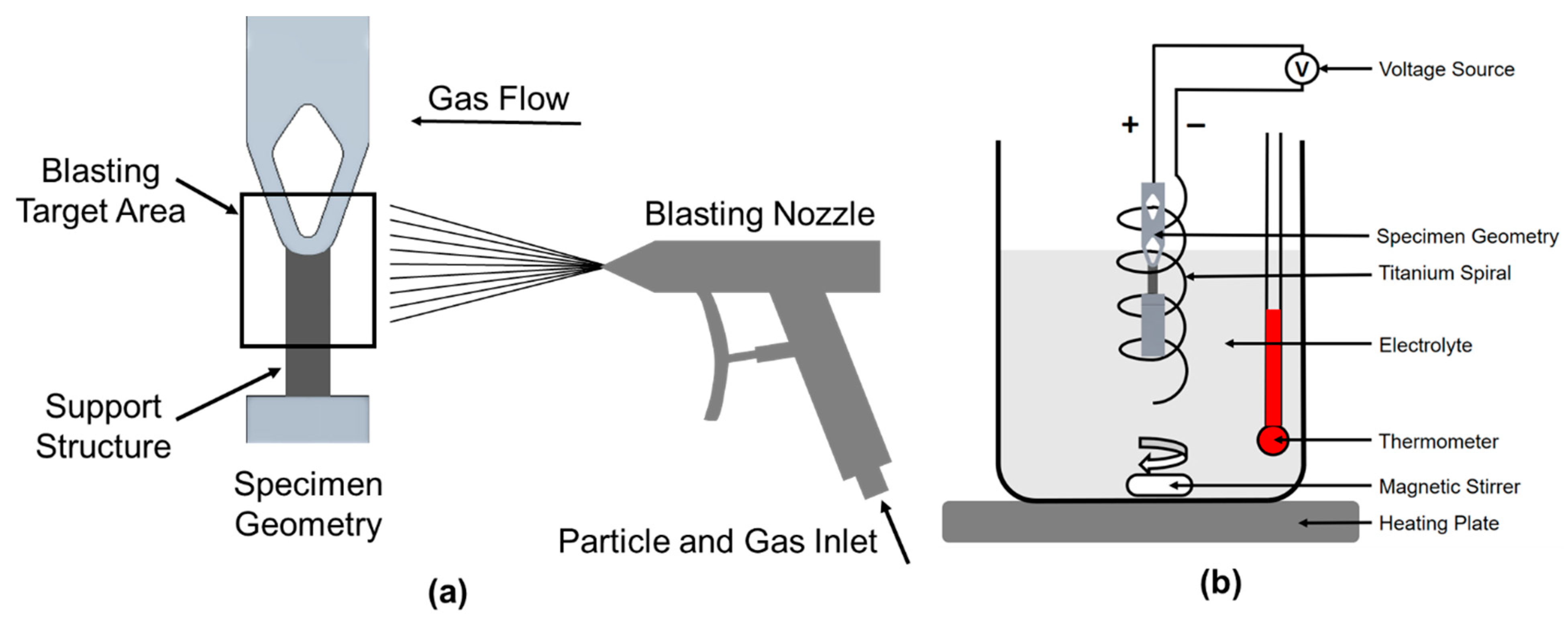
To remove the optimal support structure designs in realizing the final shape of specimen geometry, three alternative post-processing procedures were explored: two mechanical routes, SB and GB, as well as an electrochemical route, ECP. Supports were eliminated using the high kinetic energy of speeding particles in blasting processes. To avoid damaging the specimen geometry, a protective shield was used. The region of the specimen geometry not protected by the shield was exposed to the blasting as a result. The specimen geometry served as the anode in the ECP process, which followed the anodic oxidation concept. The thinnest structures in the specimen geometry are the support structures, which were eliminated first and fully.

Sand Blasting (SB)

SB employed a normal corundum with a particle size of 500–700 µm (KALO GmbH Sandstrahltechnik, Eching, Germany) to remove the support structures. The support structures were irradiated for 90 s at a pressure of P = 7.3 × 10⁵ Pa. The chemical composition of the standard corundum provided by the supplier is given in Table 3. The general blasting process is depicted schematically in Figure 1a.

Glass Bead Blasting (GB)

Glass beads (KALO GmbH Sandstrahltechnik, Eching, Germany) with a particle size of 70–110 µm were utilized to remove the support structures using GB. The support structures were irradiated for 90 s at a pressure of P = 2.4 × 10⁵ Pa. Table 4 shows the chemical composition of the glass beads provided by the supplier. Figure 1a also shows a schematic illustration of the typical blasting process.

Electrochemical Polishing (ECP)

The electrolyte used to remove the optimal support structure designs by ECP was a mixture of phosphoric acid and sulfuric acid (E268 A, Poligrat GmbH, Munich, Germany). Figure 1b depicts the experimental setup. The electrolyte was heated to roughly 65 °C, and the temperature was monitored throughout the experiment with a thermometer. A titanium spiral was utilized as the counter electrode (cathode), and a magnetic stirrer was used to generate a consistent current in the electrolyte. A voltage of 6 V within the trans-passive potential region was applied and a recorded current drop was attributed as the removal of support structures, and the experiment was terminated.

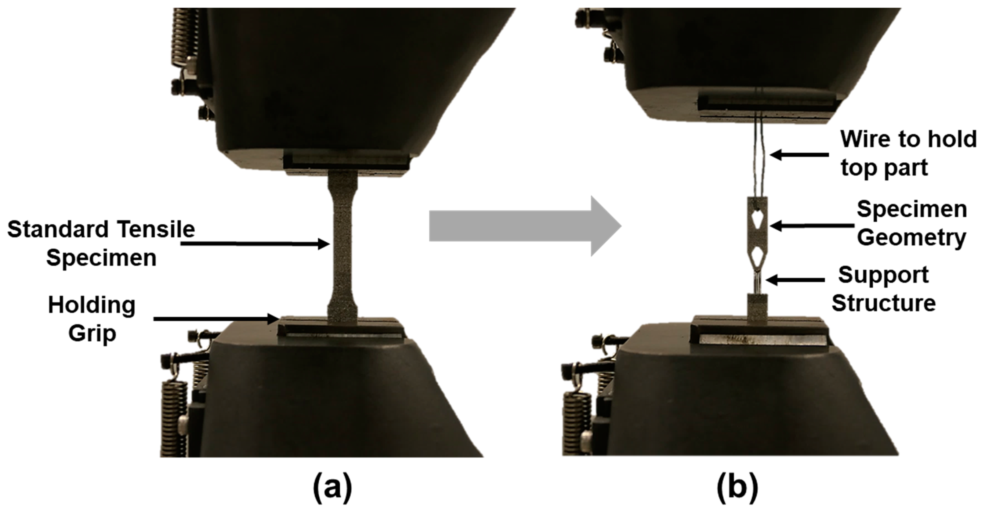
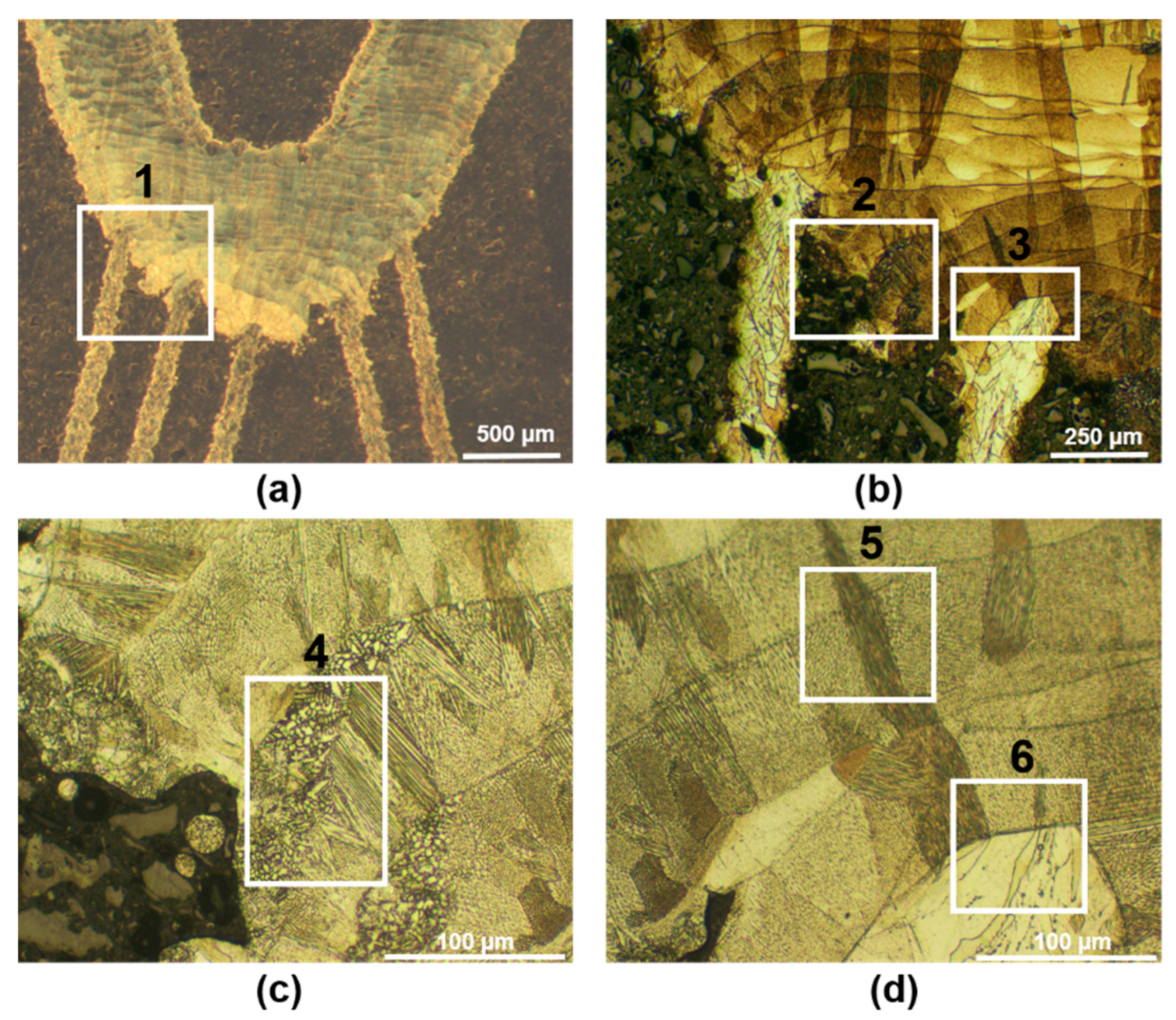
2.2.3. Mechanical Testing and Material Characterization

For the specimen geometry considered in this investigation, standardized tensile testing was not practicable. As a result, an existing uniaxial tensile testing machine with a 2 kN load cell (inspect desk 50, Hegewald & Peschke Meß und Prüftechnik GmbH, Nossen, Germany) was adapted to integrate the specimen geometry, as shown in Figure 2. To avoid the influence of any possible shear forces, the upper portion of the specimen geometry was secured to the grip of the tensile testing machine with a wire that was changed into the shape of a hook. Before beginning the real force measurements, a force of 10 N was permitted to straighten the wire. As a result, force measurements to determine the breaking load needed for support structure removal began at 10 N only. Three specimens were tested for each support structure design.
Samples were embedded in conductive resin for comprehensive microstructural analysis. These samples were finely polished using a colloidal silica suspension (0.03 µm) after being ground to P2500 grit size. Finally, a mixture of hydrochloric acid, distilled water, and nitric acid was used to etch the finely polished samples (V2A reagent). The macro- and microstructures were imaged using an Olympus light microscope.
Surface roughness (Sa and Sz) values of each sample were determined to further analyze the surface quality of as-built and post-processed samples. A LEXT OLS400 laser-scanning microscope from Olympus K.K. was used to measure roughness. The measurement area for all of the samples was approximately 0.43 mm2. For each sample, three measuring points were chosen and an average value was computed. To examine the surface quality following different support removal methods, comparable measuring locations and points were chosen to determine the surface roughness.

3. Results

In the first step, the particle size distribution (PSD) of the as-received powder SS316L particles was evaluated, and the result is given in Figure 3. PSD also showed global and local maxima at 30 µm and 50 µm, indicating a bi-modal distribution with particle sizes ranging from 15 to 65 µm, respectively. During L-PBF, a bi-modal distribution mixing diverse particle sizes is projected to improve powder flowability and eliminate powder-induced defects, resulting in improved manufacturability.

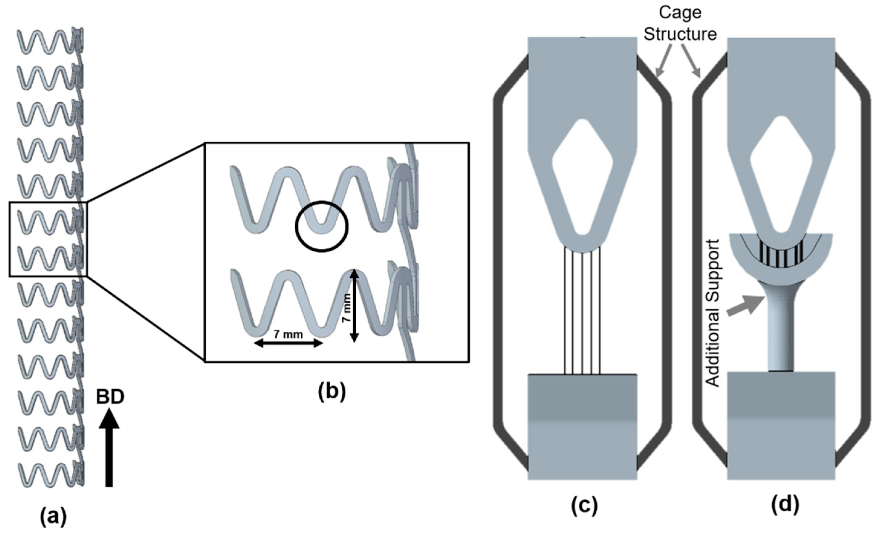
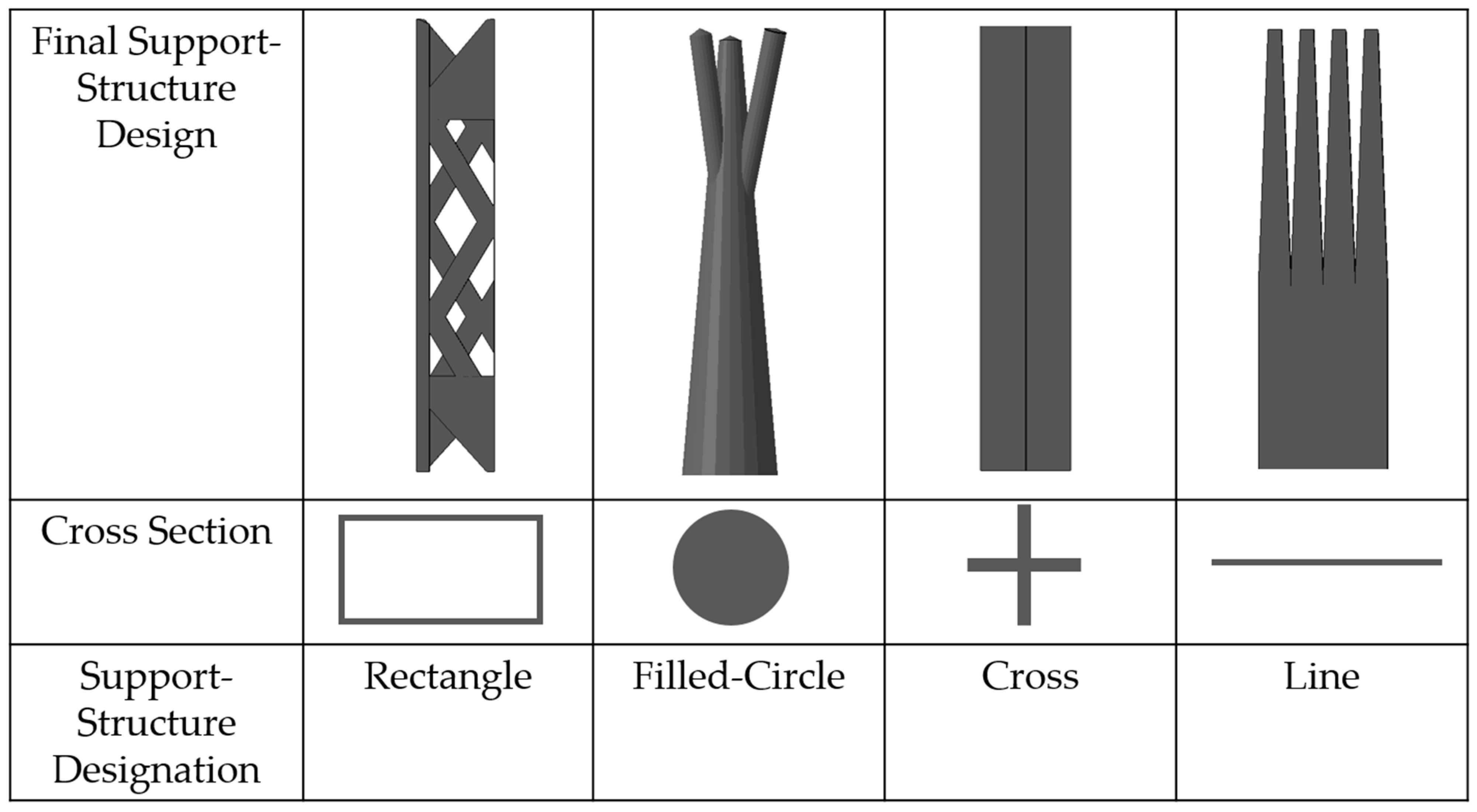
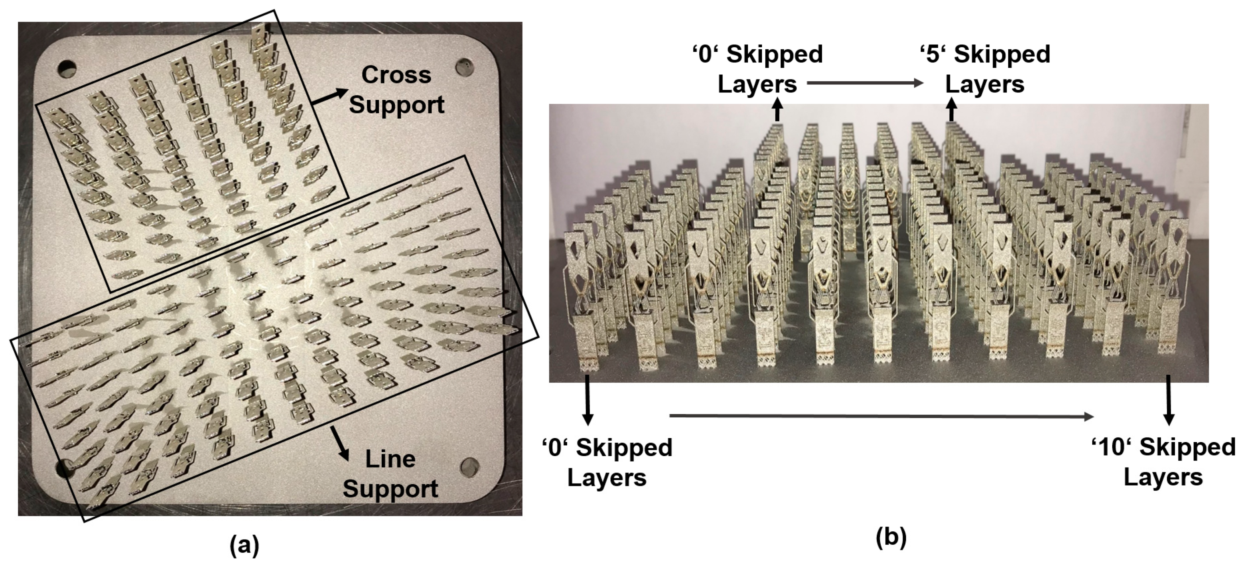
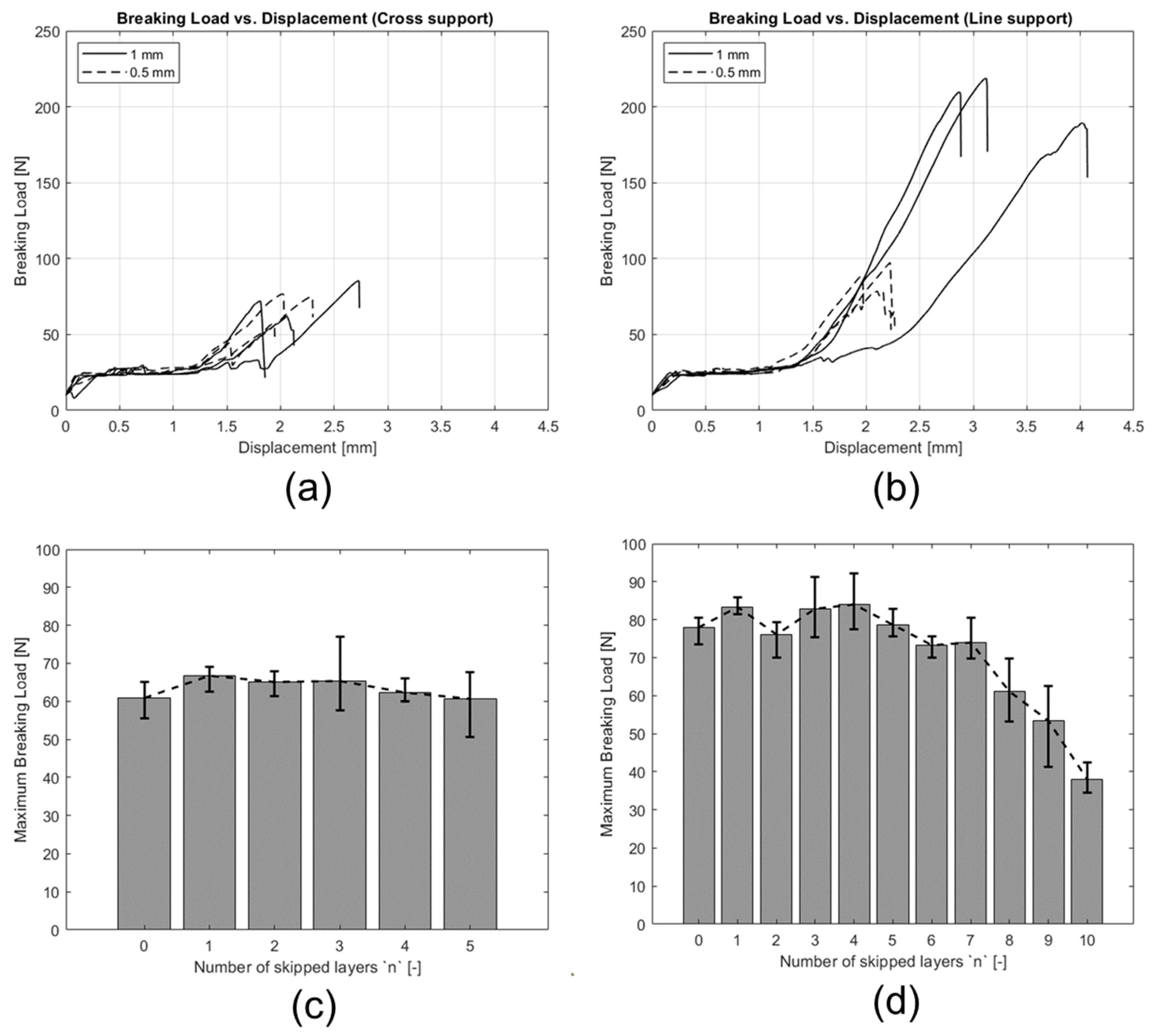
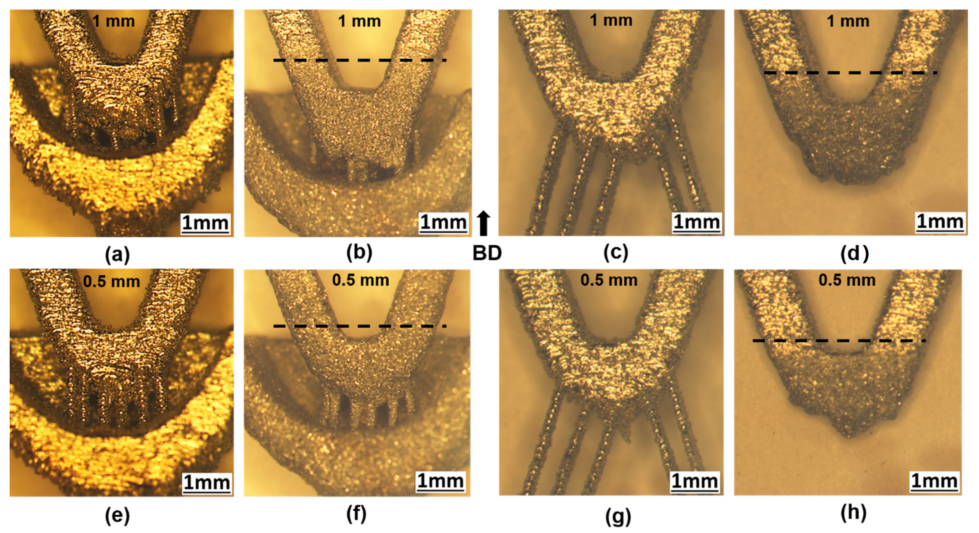
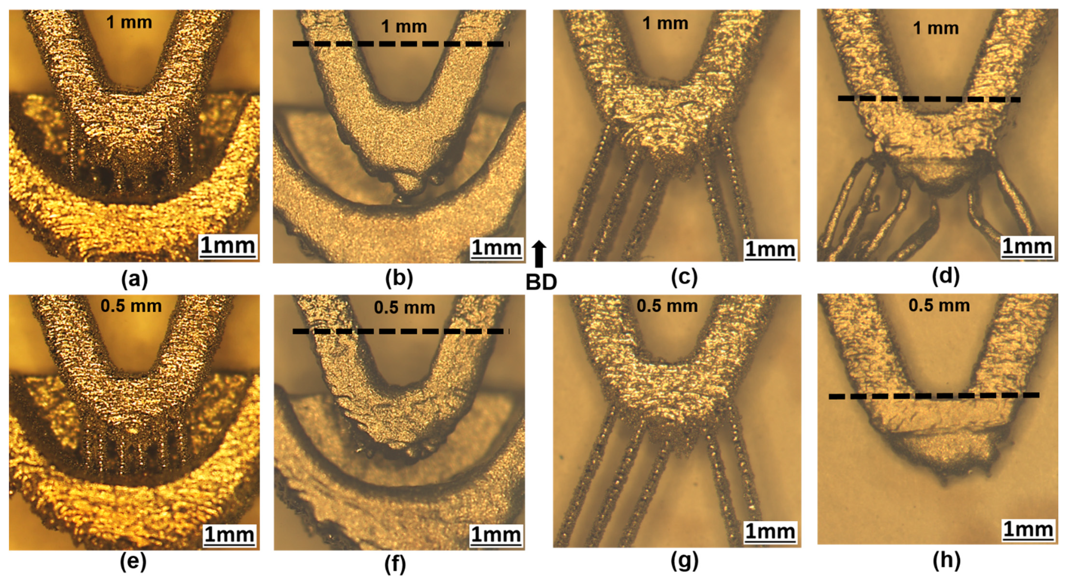
3.1. Support Structure Optimization

As shown in Figure 4a, the standard geometry of an aortic stent investigated in this study is a filigree structure (periodic lattice) composed of struts with parabolic and inverted parabolic shapes. A small portion was picked and highlighted (Figure 4b) using the approximate measurements specified within the black box for clarification on the fundamental strut design. Struts of two different thicknesses, 0.5 mm and 1 mm, were also investigated to further extend the potential of the current study into real-world applications. If the build direction (BD) is 0 degrees or vertical, the L-PBF of an aortic stent with such a design necessitates a substantial amount of support structures [35]. The support structure needs for any other design direction with respect to BD can increase significantly [23,35]. The manufacturing of a whole stent is thus unnecessary to determine an effective support structure configuration for the overhanging elements involved in this geometry, since it would require a large amount of time and material. It is worth noting that the component geometry for the inverted parabolic form, which is not an overhanging feature, does not demand a support structure. This is consistent with a study published by Wiesent et al. [36], which demonstrated that the chosen geometry is an excellent illustration of a coronary stent. As a result, in the optimization process, only a single repeating strut indicative of the entire stent is required. The support structure design alone was considered inadequate for orienting the part with regard to the build platform during L-PBF. Hence, an additional cage structure (to enhance the manufacturability and avoiding distortion) as shown in Figure 4c,d was also integrated with all the support structure designs and was removed before further testing. For the stable manufacturing of the representative stent geometry using the cross support structure considered in the present study, minimization of the distance between the base plate was essential as well. Therefore, an additional support between the base plate and specimen bottom, as shown in Figure 4d, was also incorporated. This means that the total length of the cross support was much smaller in comparison with that of the line support. More details regarding the different support structure designs are given in the subsequent sections.
Initially, four designs were explored in order to ascertain the best support structure. The four support structures were chosen based on the changes in the cross-section area exposed to the laser beam (melted layer), as shown in Figure 5. Figure 5 also includes additional information, such as the complete support structure design and the naming system followed for identifying the type of support. Based on the cross-section, the support structures are designated as rectangular, filled circle, cross, and line in the subsequent sections.
The manufacturability of the parts was investigated for all four support structures as a preliminary assessment in the design and optimization process. The representative stent geometry with the filled circle and rectangular supports had good manufacturability. However, in comparison with the cross and line supports, both of these supports had higher material consumption and, as a result, longer production times. Even with the inclusion of a cage structure, as illustrated in Figure 6, the rectangular support structure created variations in the dimensions of the actual part and the 3D CAD model (distortion). Furthermore, tensile tests of the rectangular support indicated intermittent peak loads, implying an unstable design. When a single continuous line was used for the line support, as shown in Figure 7a,b, the supports bent. As a result, the line support was redesigned as two connected lines, as shown in Figure 7c,d, and the bending issue was resolved. Line and cross supports were only examined in the later stages of the optimization process, taking into consideration the objective of the optimization method. A schematic with approximate dimensions is given in Figure S1 for a better understanding of these two support systems (supplementary file).
Cross and line supports were identified as the optimal designs based on early investigations, as they satisfied the requirements of high breaking load, minimal material consumption, and shorter production time. As illustrated in Figure 8, nine samples with line and cross supports were fabricated for each process parameter combination. The possibilities of skipping the melting within the deposited powder layers of support structures adjacent to the specimen geometry were also investigated. For the line support, the skipped layer specimens were numbered from zero (no skipping) to ten (Figure 8b). The availability of an additional support structure, as shown in Figure 4d, allowed for the skipping of up to five levels only for the cross support.
Mechanical property testing was performed to understand the breaking load requirements of different support structure designs. Cage structures were removed before the mechanical testing. Higher breaking loads resulted in more stable strut development, indicating a stronger support structure. Breaking loads were measured, plotted, and displayed in Figure 9a,b for the two different strut thicknesses. The breaking load requirements for the 0.5 mm strut thickness were found to be lower, and the results from the testing of three distinct specimens were also comparable. The load needs for specimens manufactured with the line support were higher, with a maximum load requirement of >150 N for all samples.
The possibility of skipping the melting within the deposited powder layers was explored as an additional optimization strategy. To better analyze the stability of support systems, layer skipping was combined with breaking load requirements. It should be noted that the breaking load requirements were only performed for specimens manufactured on 0.5 mm wide support structures (Figure 9c,d). As a result, the values in Figure 9c,d are lower than those in Figure 9a,b. By bypassing eight layers for the line support versus only five layers for the cross support, a nearly similar breaking load requirement was attained. The ability to skip up to eight layers during line support manufacture presents a number of possibilities for combining reduced manufacturing times with lower energy consumption.
Figure 10 and Figure 11a–d show high-magnification optical micrographs of the interface between support and fabricated specimens for the cross and line supports, respectively. The boundary between the sample and cross support is depicted in Figure 10a. The box marked 1 in Figure 10a was used to indicate a specific location, which was then depicted in detail in Figure 10b. Two different regions, one with a support and another without any support, are highlighted in Figure 10b using boxes 2 and 3. Box 4 shown in Figure 10c reveals grains that have extended their growth from the support to the sample and grown as nearly vertical columnar grains. Figure 10d depicts a defect in L-PBF that manifests itself as a lack of fusion near the bottom of a melt pool. Figure 11a,b emphasize similar regions to those indicated in Figure 10a,b. Slower cooling rates near the unsupported zones have resulted in the formation of relatively large solidification features, as shown in box 4. Columnar and equiaxed dendrites are among the observed solidification features. Figure 11d depicts long columnar grains that span the support and sample. It is worth noting that, despite the grains extending from sample to support, the solidification characteristics remained similar. Furthermore, within box 5, wider columnar grains extending between the multiple layers within the curved base region of the sample are also visible (Figure 11d).

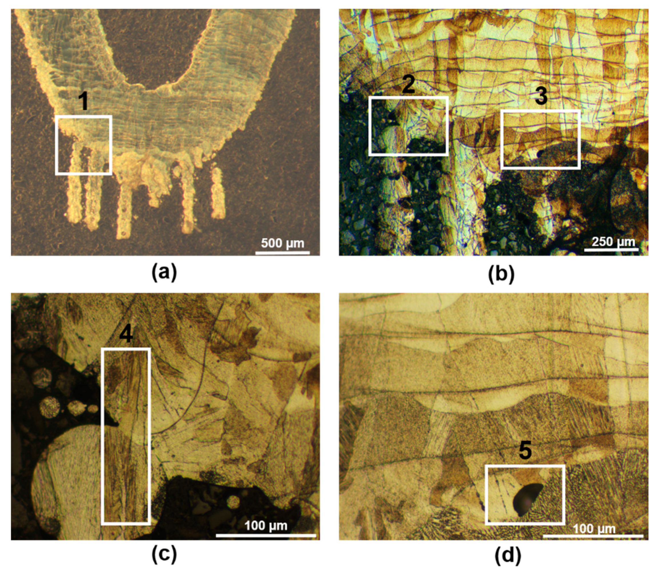
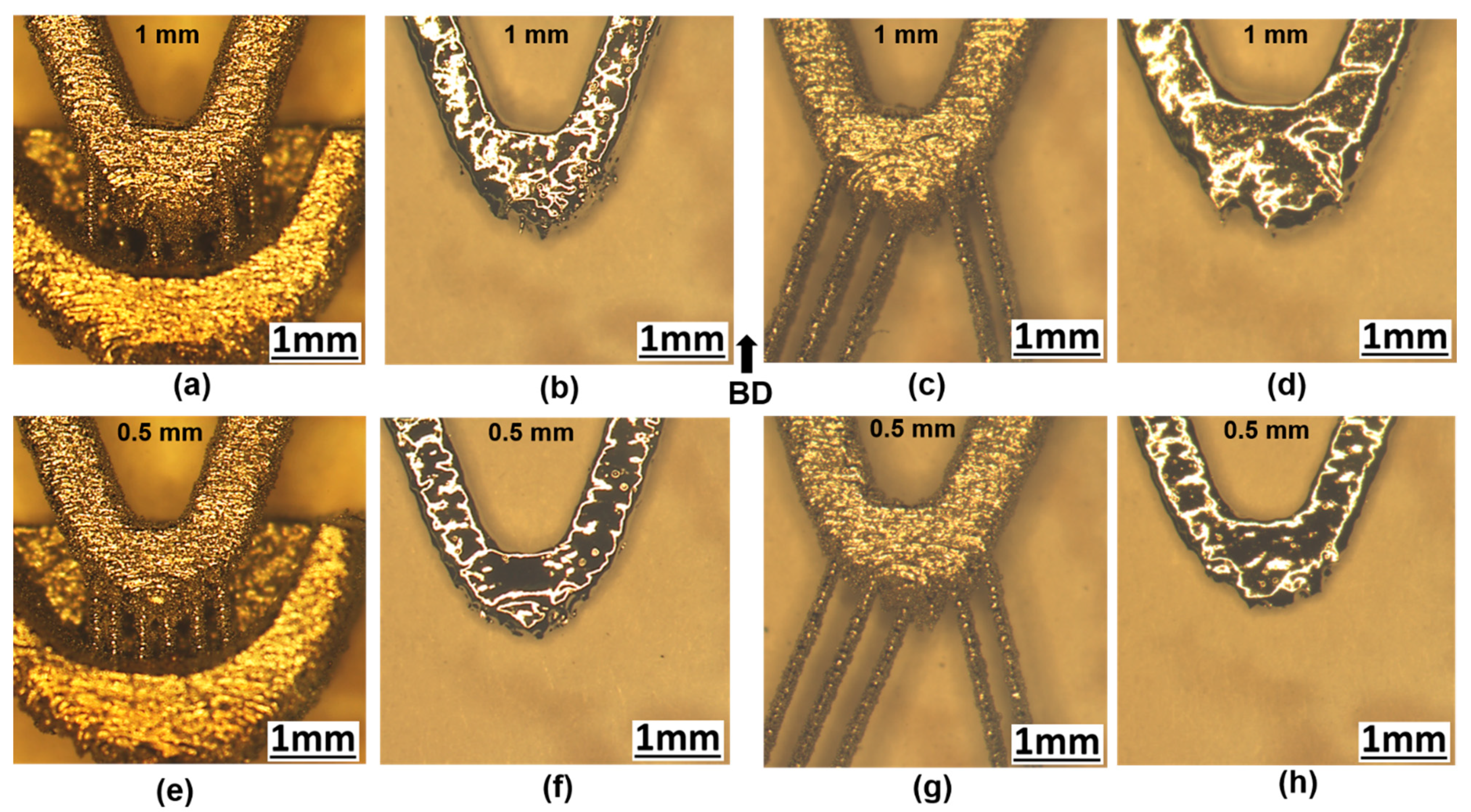
3.2. Support Removal Strategies

The removal of undesired materials (in this case, support structures) is a crucial step in achieving the final shape of the component using L-PBF. Due to the complex geometry of aortic stents, automated machining systems may not be able to reach the vicinity of the inner part of intricate features. As a result, traditional support removal processes typically involve time- and labor-intensive mechanical finishing techniques such as filing and fine grinding [28]. The difficulty level in material removal can be very high in certain situations requiring cutting followed by fine grinding, both performed manually. The issue is that manual operations may cause significant harm to the component.

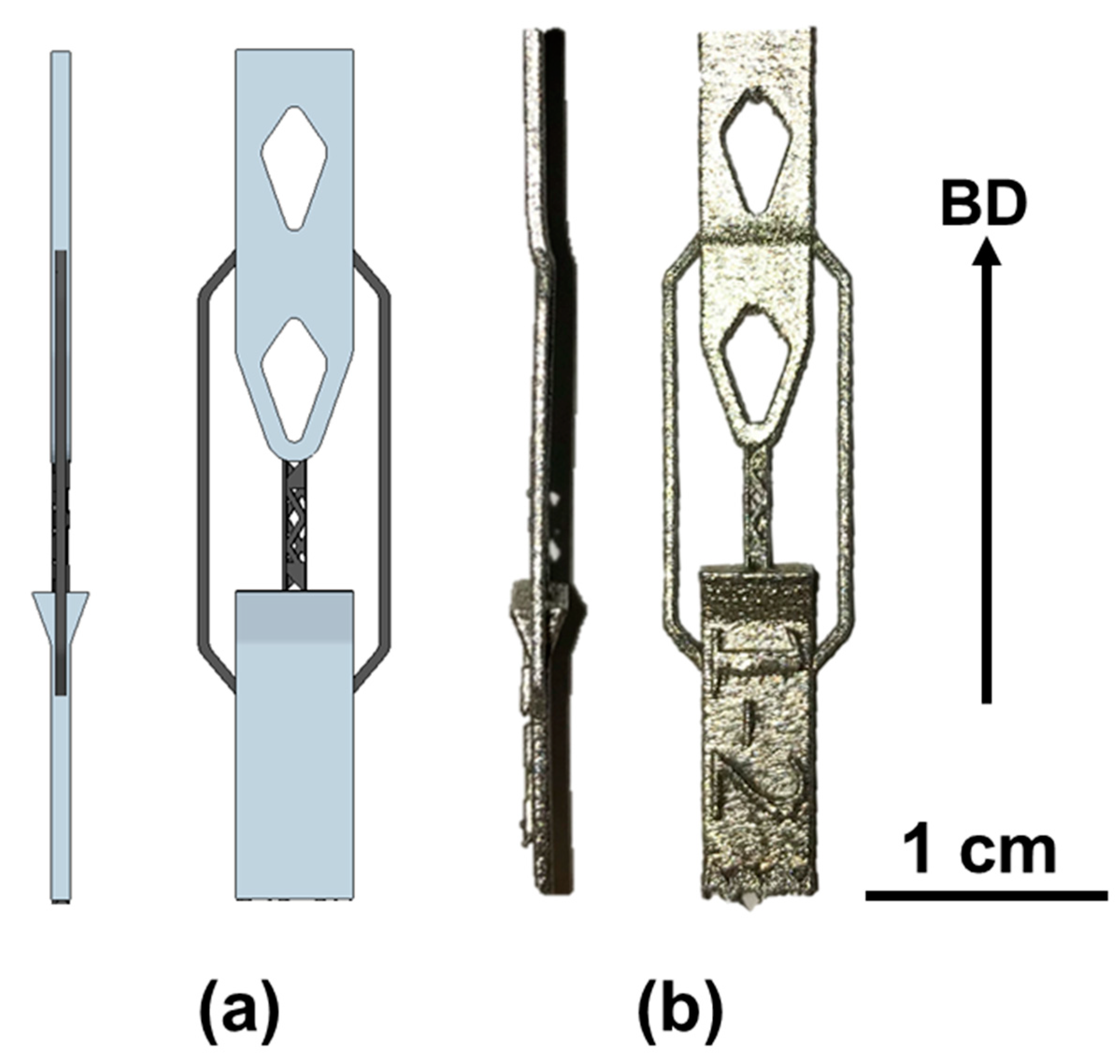
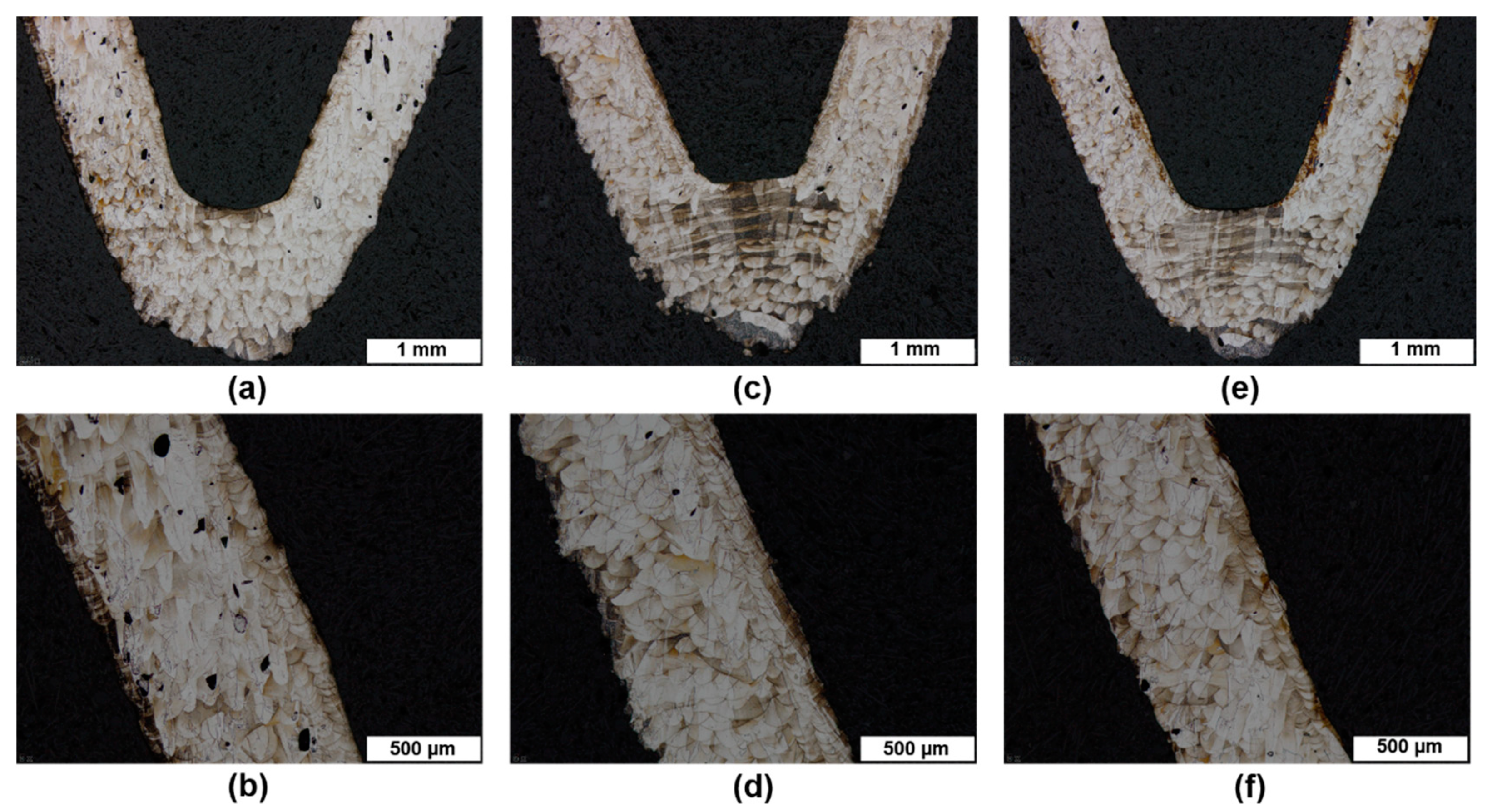
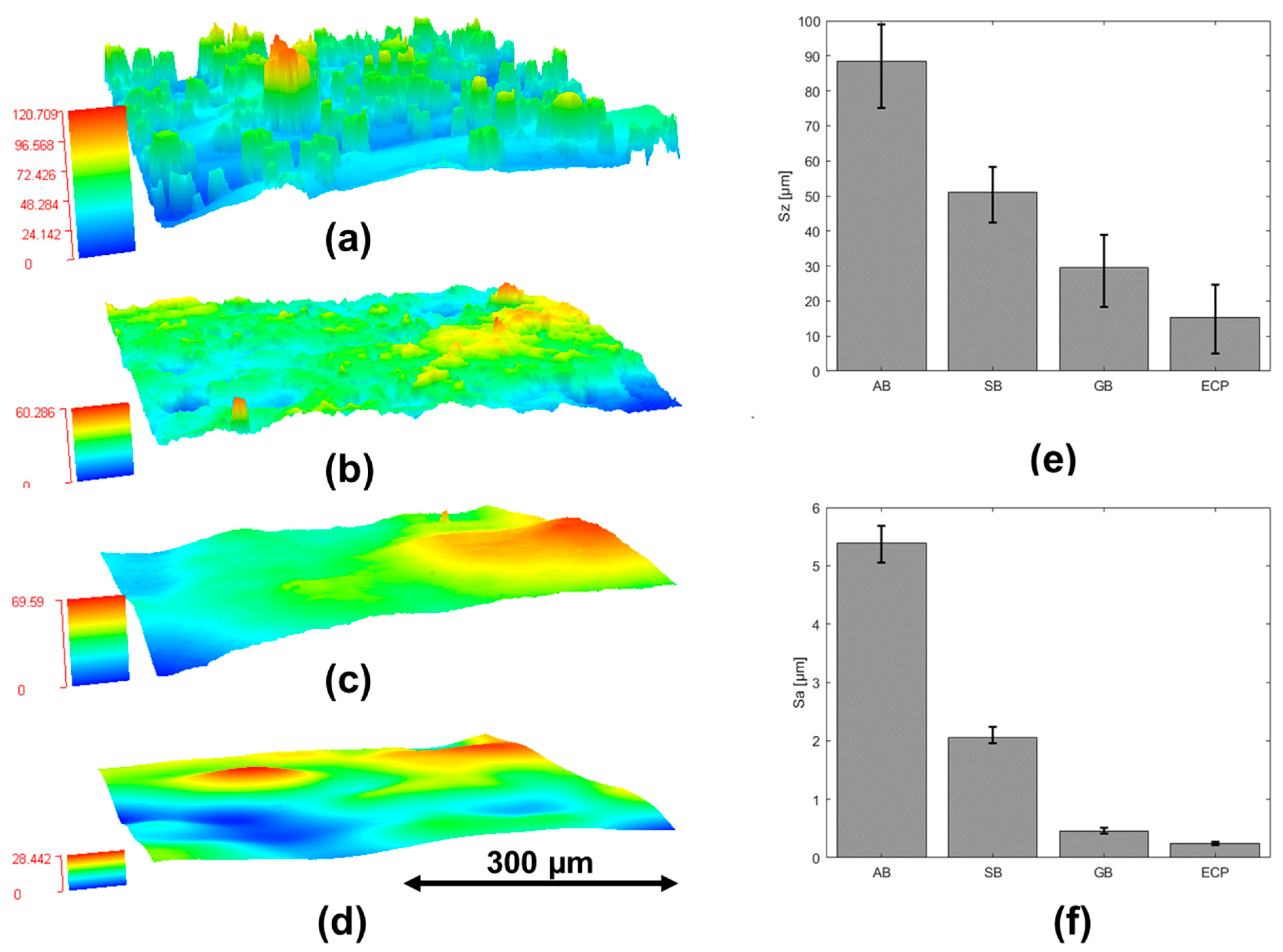
3.2.1. Sand Blasting (SB)

Optical micrographs depicting the influence of SB on the removal of cross and line supports are shown in Figure 12. It can be noted that the support removal was not completely successful for the cross support (Figure 12b,f). The sand particles were similar in size to the distance between the base of the support and the bottom of the specimen, which was the reason for the same. This, in turn, prevented sand particles from passing from front to back, even at high pressures. Similar images representing the influence of SB on the line support are given in Figure 12d,h. Sand particles were able to flow through the support structures from front to back, leading the line supports to be completely removed, as opposed to the cross support. SB was unable to remove the cross support for the two different strut thicknesses of 0.5 mm and 1 mm. However, regardless of the strut thicknesses, sand particles were able to flow through the line support and remove the support structures.

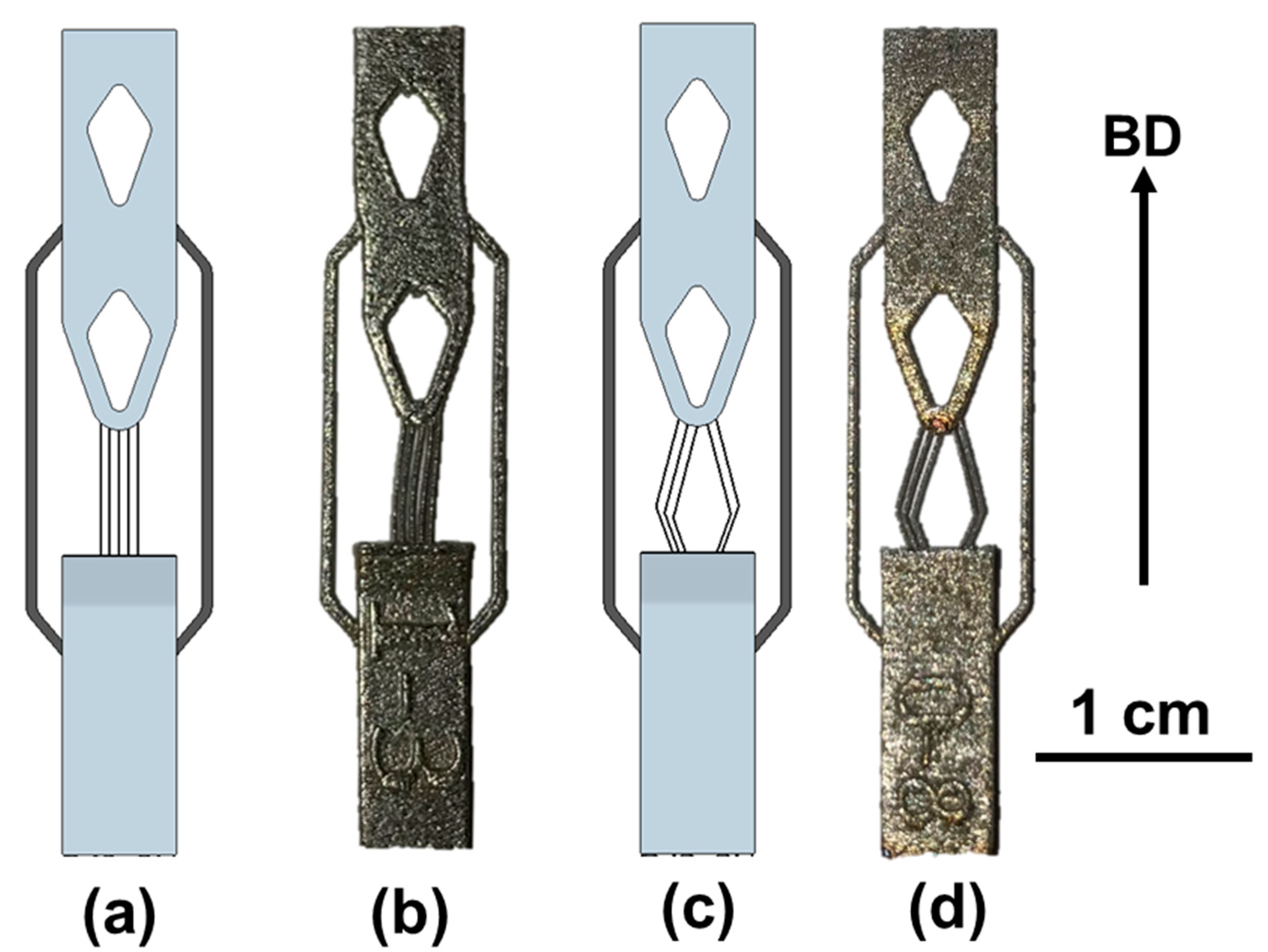
3.2.2. Glass Bead Blasting (GB)

Figure 13 shows optical micrographs depicting the effect of GB on the removal of cross and line supports. It can be observed that, irrespective of the strut thicknesses, support removal using GB was successful for the specimens fabricated using the cross support (Figure 13b,f). The specimens built with a strut thickness of 0.5 mm for the line support were successfully removed (Figure 13h). However, the strength of the glass beads were insufficient, resulting in partial support removal for struts with a thickness of 1 mm (Figure 13d). Furthermore, surface finishing was significantly better after GB than it was after SB.

3.2.3. Electrochemical Polishing (ECP)

Figure 14 shows optical micrographs depicting the effect of ECP on the removal of cross and line supports. It is worth noting that ECP had no preference for the type of support structure or the thickness of the struts. Instead, the support structures were completely removed. However, different strut thicknesses and support configurations require different amounts of polishing time. The polishing time required for the removal of the cross support was significantly longer than that necessary for the removal of the line support. Polishing durations for the line support were roughly eight minutes less than for the cross support for the same strut thickness. In contrast to the cross support, the line support had shorter polishing times due to the larger distance between the supports, which allowed for smoother electrolyte flow.

4. Discussion

Support Structure Design Optimization and Support Removal Strategies

Support structure design optimization is the preliminary step in realizing the manufacturability of a filigree structure using the L-PBF method. The integrated experimental optimization approach utilized here was established with the purpose of minimizing three factors: manufacturing time, material consumption, and post-processing time. The benefits of limitless design freedom possible by L-PBF are often sabotaged by the requirement to incorporate additional support structures in order to manufacture overhanging components for various filigree structures. As a result, designing an optimum support structure based on the specific component geometry is required for the cost- and time-effective manufacturing of components utilizing L-PBF. The reduction in manufacturing and post-processing times, as well as the associated costs, leads to a further consensus on the manufacturability of a component after incorporating the appropriate support structure designs. As a conceivable support structure, a variety of geometrical patterns are feasible. In comparison to a complicated design, a simple design that meets the essential criteria is always favored [37]. The support structure optimization followed in the present study was based on a holistic approach combining a stable support structure design and its easy removal. An overview of the performance characteristics of the different support structure designs observed during the optimization procedures is compiled in Table 5.
Most of the currently available L-PBF systems only allow the incorporation of a single powder handling system during manufacturing. Multiple powder handling systems might provide problems in terms of powder contamination and may not always be the best option [38]. As a result, it is always recommended to utilize the same powder material for both the component and the support structure. The use of the same powder material as the raw material for manufacturing support structures might result in higher material consumption and later in significant additional material wastage. Thus, the discarding of the support material often parallels the disadvantage of material removal in subtractive manufacturing methods such as machining. According to the performance attributes matrix in Table 5, incorporating a line support required the lowest amount of material and the shortest manufacturing time. Furthermore, the breaking load requirements were rather high, and support removal through all post-processing methods seemed straightforward. The improved line support design explored in this study as a combination of two lines connected with an included angle of 145° offered sufficient stability for the component during manufacturing. The choice of a 145° angle was made to minimize further material waste in the form of producing another support for the support structure. For any angle < 45° from the horizontal, the manufacturing of support structures requires the help of additional supports [23]. Thus, for the bottom part of the line support, an angle of 70° in the counterclockwise direction from the horizontal was chosen and, for the top part, an angle of 75° in the clockwise direction from the same horizontal. This makes the total included angle 145°. In addition to this, the sufficient gap available between the different line support structures made it easier for the sand and glass particles during blasting, as well as the electrolyte, to move during ECP. Thus, the improved performance of the line support in comparison with other support structures can be attributed to the modified design.
A clear distinction and dependence of the type of support structure on the support removal strategies was observed. ECP was established as an efficient support removal strategy irrespective of the type of support and strut thicknesses. However, noted differences were observed in the polishing times depending on the type of support structure and the strut thicknesses. Even with the highest efficacy for support removal, the chemical nature of the ECP method persists as a concern. Electrolyte handling and discarding requires care because of the acidic ingredients involved. Even at a high pressure such as 7.3 × 10⁵ Pa, used to irradiate the support structure, the sand particles were unable to penetrate the cross support due to their relatively large size. This has led to some deformation within the support structures, without being able to remove them from the specimen geometry. GB was successful in removing the cross support irrespective of the strut thicknesses.
The manufactured specimen geometry is composed of a curved base and two struts that are held at an angle to the vertical. Hence, for an enhanced understanding of the influence of support removal strategies, the specific characteristics of these individual features are shown in Figure 15. High-magnification optical micrographs representing the boundary between the support and sample (curved base) after the support removal are depicted in Figure 15a–c. In addition to this, a representative single strut (left) of the manufactured samples is also shown in Figure 15d–f. The curved base as well as the strut reveal a significant amount of visible pores in Figure 15a–d corresponding to the specimen manufactured on the cross support. However, the amount of visible porosity was significantly reduced for the specimens fabricated using the line support. For the identical laser beam parameters used for the manufacturing of supports and specimens, the curved base (bottom) part of the components manufactured using the line support revealed identical microstructures in the form of some darker regions. These darker regions corresponded to the overlapping regions of consecutive melt pool boundaries. In contrast, the darker regions were only visible around the inner boundary of the curvature in the specimen manufactured using the cross support. Thus, it was confirmed that the type of support had a significant impact in determining the porosity and microstructure of the manufactured components.
In comparison to the line support, the cross support exposed a relatively broad area to the laser beam in a single step. This meant that there was more material available for the support to perform its additional role as a heat sink during manufacturing. The availability of additional solid material in the bottom as a support allows for better heat conduction during specimen fabrication. Higher cooling rates are caused by faster heat conduction, resulting in the formation of finer solidification features within the strut. Due to the relatively smaller solidification structures, the light microscopic images of the same magnification displayed in Figure 15a–c for the specimen geometry manufactured utilizing the cross support (Figure 15a) did not disclose any darker regions.
Further qualitative and quantitative assessment of the performance quality of the different support removal strategies is depicted in Figure 16a–f using the surface roughness profile comparisons between the as-built state and after different post-processing routes. The surface roughness values in terms of Sz (maximum height) and Sa (arithmetical mean height) are plotted in Figure 16e–f. The surface roughness indicated by the Sz values is relatively high for the as-built state, with the maximum roughness reaching 120 µm. SB reduced the maximum Sz value to ~60 µm, albeit with non-uniform roughness throughout the measured locations within the sample. Maximum Sz values observed for the GB were comparable to those obtained after SB. However, the maximum Sz value was observed only close to one edge within the measurement area. This could be due to the presence of a single large particle or an agglomerated region that was not able to be eliminated completely using the GB. Minimum values of Sz and Sa were observed for GB and ECP, with Sa values less than 1 µm indicating the high efficiency of these two post-processing methods in realizing the final shape of the component. The obtained roughness values are closer to that required for the biomedical application of stents [22].
Numerous research studies have proven that the successful manufacturing of stents/lattice structures using L-PBF is possible if the relevant design rules are obeyed [21,22,23,39,40]. The specific advantage of L-PBF systems is that they allow the variation of a number of laser parameters in coalition, making it possible to achieve the near-net-shape manufacturing of stents [21]. Traditional manufacturing of the stents, involving micro-tubing followed by laser cutting, can lead to non-uniform surface properties [41]. However, further post-processing treatments are needed because of the stringent requirements regarding the final product specifications in a highly regulated field such as medical technology. Typical post-processing methods include heat treatment and chemical or electrochemical polishing. Thus, the relevance of an integrative approach combining the support optimization and support removal as followed in the present study is essential to achieve the successful near-net-shape manufacturing of stents using L-PBF. Excluding the time required for post-processing treatments, lower manufacturing times up to one third of that required for laser cutting for a single coronary stent have been reported [22]. Significant improvements in the time required for support removal using the ECP method for the representative aortic stent geometry using a line support was observed in the present study. Similar time requirements are therefore expected during the removal of support structures from the whole stent geometry. Therefore, the successful support removal within eighteen minutes for the heaviest sample having a strut thickness of 1 mm for the representative aortic stent geometry manufactured using a line support confirms the efficacy of the holistic approach followed here. Thus, the overall performance characteristics from the optimization of support structure designs and support removal strategies indicate that the incorporation of a line support followed by ECP is one of the most feasible ways to achieve the near-net-shape manufacturing of filigree components such as aortic stents through L-PBF.
The majority of previous and ongoing L-PBF research initiatives focus on the near-net-shape fabrication of solid components with complicated geometries [42]. The design flexibility provided by L-PBF has sparked renewed interest in manufacturing lattice structures, including auxetic structures with a negative Poisson’s ratio [27,28]. To separate the supports from solid components, electrical discharge machining, also known as wire cutting, is extensively utilized [43]. Fabricated components, which are typically heavier than the support structures incorporated, allow for optimal component retention following support removal. Size effects can cause additional challenges when an established method such as wire cutting used for solid components is attempted for removing support structures from filigree structures. A critical challenge here in fabricating overhanging features for the lattice and auxetic structures similar to aortic stents is the design of an optimal support structure allowing sufficient stability during manufacturing. In addition to this, the support structures need to be manufactured in the shortest possible time with the lowest material consumption. Even though support structure optimization has been investigated in detail by many researchers [12,32,33], specific investigations on the influence of support structure removal strategies had not been carried out in L-PBF research until now. Instead, the focus was mostly on improving the surface properties of the final components in achieving the required surface roughness specifications [44,45]. This was mostly attributed to the difficulties involved in dealing with miniature-sized specimen geometries. In addition, approaching the support structure design optimization and support removal strategies as separate challenges can further complicate the research problem and prevent researchers from obtaining a feasible solution. Therefore, the integrative experimental approach followed in the present study appears to be a precise methodology for realizing the near-net-shape manufacturing of filigree structures such as aortic stents.
Sustainable manufacturing technologies such as bio-machining offer a promising route to achieve the surface finishing requirements of a filigree structure such as the stent geometry investigated in the present study. Diaz-Tena et al. [46] reported the successful material removal of pure copper using extremophile bacteria. The authors also reported that the final surface quality can be tailored using the concentration of bacteria. The authors also proposed reliable methodologies to machine complex geometries similar to stents using the same sustainable concept. Future investigations are planned using these bio-machining concepts to realize the stringent requirements of biomedical applications using sustainable and environmentally friendly methods.

5. Conclusions

An integrative experimental approach was devised to combine support structure design optimization with an optimal support removal procedure for L-PBF-manufactured filigree structures. Based on the area that was exposed to the laser beam, four support structure designs (rectangular, filled circle, line, and cross) were identified in the first step, and in the subsequent step, two of the most efficient designs were selected for further investigations. Skipping of the layers from laser exposure was attempted in order to compensate for some of the manufacturing time used for fabricating the supports. It was observed that the production time can be reduced without sacrificing the stability provided by support structures by skipping the laser exposure within some of the deposited powder layers. For the removal of optimized support structure designs, SB and GB were attempted due to their wide use in industrial applications. ECP, which was previously used for enhancing the surface properties of the manufactured components, was also attempted as a new strategy for support removal. A modified line support structure design consisting of two straight lines with an included angle of 145° proved to be an optimal design, requiring a shorter manufacturing time, lower material consumption, and a higher breaking load requirement. This design also allowed the skipping of up to eight layers. ECP was identified as an efficient strategy for the complete removal of the line support within fifteen minutes. The three support removal strategies, SB, GB, and ECP, were able to significantly reduce the surface roughness in comparison with the as-built state. By using ECP, the arithmetic mean of the surface roughness values Sa was reduced by up to 0.25 µm. Further possibilities regarding the maximum number of skipped layers are yet to be explored for an optimal support structure design that could further reduce the manufacturing time. A future investigation in this approach will look into the potential of extending layer skipping during the fabrication of real filigree structures rather than the supporting structures.

Supplementary Materials

The following are available online at https://www.mdpi.com/article/10.3390/app11199176/s1, Figure S1. Schematic representations with the approximate dimensions for the two different (a) and (b) support structure designs used in reference with the line support; (c) dimensions of the cross support with the front (left) and top (right) views.

Author Contributions

Conceptualization, M.G., N.N. and P.L.; methodology, M.G., U.S. and P.L.; software, M.G.; validation, U.N., P.L. and N.N.; formal analysis, N.N.; investigation, M.G. and U.S.; resources, P.L and U.N.; data curation, N.N.; writing—original draft preparation, M.G. and N.N.; writing—review and editing, N.N. and U.N; visualization, M.G.; supervision, P.L. and N.N.; project administration, U.N.; funding acquisition, U.N. All authors have read and agreed to the published version of the manuscript.

Funding

The German Federal Ministry of Education and Research (BMBF) funded this research within the framework of SME-innovative: medical engineering, Aortic Gen-i-Stent grant number 13GW0391B.

Data Availability Statement

All the relevant data are included within the manuscript. The data presented in this study are available on request from the corresponding author. Some of the data are not publicly available due to the confidentiality agreement between the industry partner and the university.

Conflicts of Interest

The authors declare no conflict of interest. The funders had no role in the design of the study; in the collection, analyses, or interpretation of data; in the writing of the manuscript, or in the decision to publish the results.

References

  1. Marini, D.; Cunningham, D.; Corney, J.R. Near net shape manufacturing of metal: A review of approaches and their evolutions. Proc. Inst. Mech. Eng. Part B J. Eng. Manuf. 2018, 232, 650–669. [Google Scholar] [CrossRef] [Green Version]
  2. Mandal, D. Near Net Shape Casting through Investment, Die and Centrifugal Casting. CAFP-2008; Special Metal Casting and Forming Processes. pp. 1–19. Available online: http://eprints.nmlindia.org/5867 (accessed on 11 July 2021).
  3. Taminger, K.M.; Hafley, R.A. Electron beam freeform fabrication for cost effective near-net shape manufacturing. Nato AVT 2006, 139, 16-1–16-10. [Google Scholar]
  4. Wu, X.-H.; Mei, J. Near net shape manufacturing of components using direct laser fabrication technology. J. Mater. Process. Technol. 2003, 135, 266–270. [Google Scholar] [CrossRef]
  5. Pérez, J.D.; de Lacalle, L.N.; Urbikain, G.; Pereira, O.; Martínez, S.; Bris, J. On the relationship between cutting forces and anisotropy features in the milling of LPBF Inconel 718 for near net shape parts. Int. J. Mach. Tools Manuf. 2021, 103801. [Google Scholar] [CrossRef]
  6. Yang, S.; Tang, Y.; Zhao, Y.F. A new part consolidation method to embrace the design freedom of additive manufacturing. J. Manuf. Process. 2015, 20, 444–449. [Google Scholar] [CrossRef] [Green Version]
  7. Cunningham, C.R.; Flynn, J.M.; Shokrani, A.; Dhokia, V.; Newman, S.T. Invited review article: Strategies and processes for high quality wire arc additive manufacturing. Addit. Manuf. 2018, 22, 672–686. [Google Scholar] [CrossRef]
  8. Wu, B.; Pan, Z.; Ding, D.; Cuiuri, D.; Li, H.; Xu, J.; Norrish, J. A review of the wire arc additive manufacturing of metals: Properties, defects and quality improvement. J. Manuf. Process. 2018, 35, 127–139. [Google Scholar] [CrossRef]
  9. Hufenbach, J.; Sander, J.; Kochta, F.; Pilz, S.; Voss, A.; Kühn, U.; Gebert, A. Effect of selective laser melting on microstructure, mechanical, and corrosion properties of biodegradable FeMnCS for implant applications. Adv. Eng. Mater. 2020, 22, 2000182. [Google Scholar] [CrossRef]
  10. Mukherjee, T.; Zhang, W.; DebRoy, T. An improved prediction of residual stresses and distortion in additive manufacturing. Comput. Mater. Sci. 2017, 126, 360–372. [Google Scholar] [CrossRef] [Green Version]
  11. Jiang, J.; Xu, X.; Stringer, J. Support structures for additive manufacturing: A review. J. Manuf. Mater. Process. 2018, 2, 64. [Google Scholar] [CrossRef] [Green Version]
  12. Strano, G.; Hao, L.; Everson, R.M.; Evans, K.E. A new approach to the design and optimisation of support structures in additive manufacturing. Int. J. Adv. Manuf. Technol. 2013, 66, 1247–1254. [Google Scholar] [CrossRef]
  13. Ameen, W.; Al-Ahmari, A.; Mohammed, M.K.; Mian, S.H. Manufacturability of overhanging holes using electron beam melting. Metals 2018, 8, 397. [Google Scholar] [CrossRef] [Green Version]
  14. Mhapsekar, K.; McConaha, M.; Anand, S. Additive manufacturing constraints in topology optimization for improved manufacturability. J. Manuf. Sci. Eng. 2018, 140. [Google Scholar] [CrossRef]
  15. Han, Q.; Gu, H.; Soe, S.; Setchi, R.; Lacan, F.; Hill, J. Manufacturability of AlSi10Mg overhang structures fabricated by laser powder bed fusion. Mater. Des. 2018, 160, 1080–1095. [Google Scholar] [CrossRef]
  16. Nadammal, N.; Kromm, A.; Saliwan-Neumann, R.; Farahbod, L.; Haberland, C.; Portella, P.D. Influence of support configurations on the characteristics of selective laser-melted inconel 718. JOM 2018, 70, 343–348. [Google Scholar] [CrossRef]
  17. Golledge, J. Abdominal aortic aneurysm: Update on pathogenesis and medical treatments. Nat. Rev. Cardiol. 2019, 16, 225–242. [Google Scholar] [CrossRef]
  18. Golledge, J.; Moxon, J.V.; Singh, T.P.; Bown, M.J.; Mani, K.; Wanhainen, A. Lack of an effective drug therapy for abdominal aortic aneurysm. J. Intern. Med. 2020, 288, 6–22. [Google Scholar] [CrossRef] [Green Version]
  19. Demanget, N.; Duprey, A.; Badel, P.; Orgéas, L.; Avril, S.; Geindreau, C.; Albertini, J.N.; Favre, J.P. Finite element analysis of the mechanical performances of 8 marketed aortic stent-grafts. J. Endovasc. Ther. 2013, 20, 523–535. [Google Scholar] [CrossRef] [PubMed] [Green Version]
  20. Troisi, N.; Torsello, G.; Donas, K.P.; Austermann, M. Endurant stent-graft: A 2-year, single-center experience with a new commercially available device for the treatment of abdominal aortic aneurysms. J. Endovasc. Ther. 2010, 17, 439–448. [Google Scholar] [CrossRef]
  21. Zhang, L.; Chen, X.; Liu, M. Research of customized aortic stent graft manufacture. In IOP Conference Series: Materials Science and Engineering; IOP Publishing: Hong Kong, 2016; Volume 187, p. 012027. [Google Scholar] [CrossRef]
  22. Demir, A.G.; Previtali, B. Additive manufacturing of cardiovascular CoCr stents by selective laser melting. Mater. Des. 2017, 119, 338–350. [Google Scholar] [CrossRef] [Green Version]
  23. Finazzi, V.; Demir, A.G.; Biffi, C.A.; Chiastra, C.; Migliavacca, F.; Petrini, L.; Previtali, B. Design rules for producing cardiovascular stents by selective laser melting: Geometrical constraints and opportunities. Procedia Struct. Integr. 2019, 15, 16–23. [Google Scholar] [CrossRef]
  24. Wessarges, Y.; Hagemann, R.; Gieseke, M.; Noelke, C.; Kaierle, S.; Schmidt, W.; Schmitz, K.P.; Haferkamp, H. Additive manufacturing of vascular implants by selective laser melting. Biomed. Eng.-Biomed. Tech. 2014, 59, S401–S404. [Google Scholar]
  25. Fischer, J.; Kniepkamp, M.; Abele, E. Micro laser melting: Analyses of current potentials and restrictions for the additive manufacturing of micro structures. In Proceedings of the 25th Annual International Solid Freeform Fabrication Symposium—An Additive Manufacturing Conference, Austin, TX, USA, 4–6 August 2014; pp. 4–6. [Google Scholar]
  26. Bhullar, S.K.; Hewage, A.M.; Alderson, A.; Alderson, K.; Jun, M.B. Influence of negative Poisson’s ratio on stent applications. Adv. Mater. 2013, 2, 42–47. [Google Scholar] [CrossRef]
  27. Geng, L.C.; Ruan, X.L.; Wu, W.W.; Xia, R.; Fang, D.N. Mechanical properties of selective laser sintering (SLS) additive manufactured chiral Auxetic cylindrical stent. Exp. Mech. 2019, 59, 913–925. [Google Scholar] [CrossRef]
  28. Calleja-Ochoa, A.; Gonzalez-Barrio, H.; Lacalle, N.L.; Martínez, S.; Albizuri, J.; Lamikiz, A. A New Approach in the Design of Microstructured Ultralight Components to Achieve Maximum Functional Performance. Materials 2021, 14, 1588. [Google Scholar] [CrossRef] [PubMed]
  29. Kuo, Y.H.; Cheng, C.C.; Lin, Y.S.; San, C.H. Support structure design in additive manufacturing based on topology optimization. Struct. Multidiscip. Optim. 2018, 57, 183–195. [Google Scholar] [CrossRef]
  30. Zhou, M.; Liu, Y.; Lin, Z. Topology optimization of thermal conductive support structures for laser additive manufacturing. Comput. Methods Appl. Mech. Eng. 2019, 353, 24–43. [Google Scholar] [CrossRef]
  31. Bartsch, K.; Lange, F.; Gralow, M.; Emmelmann, C. Novel approach to optimized support structures in laser beam melting by combining process simulation with topology optimization. J. Laser Appl. 2019, 31, 022302. [Google Scholar] [CrossRef]
  32. Cheng, L.; Liang, X.; Bai, J.; Chen, Q.; Lemon, J.; To, A. On utilizing topology optimization to design support structure to prevent residual stress induced build failure in laser powder bed metal additive manufacturing. Addit. Manuf. 2019, 27, 290–304. [Google Scholar] [CrossRef]
  33. Gan, M.X.; Wong, C.H. Practical support structures for selective laser melting. J. Mater. Process. Technol. 2016, 238, 474–484. [Google Scholar] [CrossRef]
  34. Mukhametkaliyev, T.M.; Ferrucci, M.; Pavan, M.; Villanueva, M.C.; Craeghs, T.; Claeys, C.; Deckers, E.; Desmet, W. Optimization of the Additive Manufacturing Process for Geometrically Complex Vibro-acoustic Metamaterials. In Proceedings of the 30th Annual International Solid Freeform Fabrication Symposium–An Additive Manufacturing Conference, Austin, TX, USA, 12–14 August 2019. [Google Scholar]
  35. Wang, D.; Yang, Y.; Yi, Z.; Su, X. Research on the fabricating quality optimization of the overhanging surface in SLM process. Int. J. Adv. Manuf. Technol. 2013, 65, 1471–1484. [Google Scholar] [CrossRef]
  36. Wiesent, L.; Schultheiß, U.; Schmid, C.; Schratzenstaller, T.; Nonn, A. Experimentally validated simulation of coronary stents considering different dogboning ratios and asymmetric stent positioning. PLoS ONE 2019, 14, e0224026. [Google Scholar] [CrossRef] [Green Version]
  37. Nelaturi, S.; Behandish, M.; Mirzendehdel, A.M.; de Kleer, J. Automatic support removal for additive manufacturing post processing. Comput.-Aided Des. 2019, 115, 135–146. [Google Scholar] [CrossRef] [Green Version]
  38. Horn, M.; Langer, L.; Schafnitzel, M.; Dietrich, S.; Schlick, G.; Seidel, C.; Reinhart, G. Influence of metal powder cross-contaminations on part quality in Laser Powder Bed Fusion: Copper alloy particles in maraging steel feedstock. Procedia CIRP 2020, 94, 167–172. [Google Scholar] [CrossRef]
  39. Finazzi, V.; Demir, A.G.; Biffi, C.A.; Migliavacca, F.; Petrini, L.; Previtali, B. Design and functional testing of a novel balloon-expandable cardiovascular stent in CoCr alloy produced by selective laser melting. J. Manuf. Process. 2020, 55, 161–173. [Google Scholar] [CrossRef]
  40. Meboldt, M.; Klahn, C. (Eds.) Industrializing Additive Manufacturing: Proceedings of AMPA2020; Springer Nature AG Switzerland: Cham, Switzerland, 2020. [Google Scholar]
  41. Langi, E.; Zhao, L.G.; Jamshidi, P.; Attallah, M.M.; Silberschmidt, V.V.; Willcock, H.; Vogt, F. Microstructural and mechanical characterization of thin-walled tube manufactured with selective laser melting for stent application. J. Mater. Eng. Perform. 2021, 30, 696–710. [Google Scholar] [CrossRef]
  42. Druzgalski, C.L.; Ashby, A.; Guss, G.; King, W.E.; Roehling, T.T.; Matthews, M.J. Process optimization of complex geometries using feed forward control for laser powder bed fusion additive manufacturing. Addit. Manuf. 2020, 34, 101169. [Google Scholar] [CrossRef]
  43. Nadammal, N.; Cabeza, S.; Mishurova, T.; Thiede, T.; Kromm, A.; Seyfert, C.; Farahbod, L.; Haberland, C.; Schneider, J.A.; Portella, P.D.; et al. Effect of hatch length on the development of microstructure, texture and residual stresses in selective laser melted superalloy Inconel 718. Mater. Des. 2017, 134, 139–150. [Google Scholar] [CrossRef]
  44. Khan, H.M.; Karabulut, Y.; Kitay, O.; Kaynak, Y.; Jawahir, I.S. Influence of the post-processing operations on surface integrity of metal components produced by laser powder bed fusion additive manufacturing: A review. Mach. Sci. Technol. 2020, 25, 118–176. [Google Scholar] [CrossRef]
  45. Yang, K.T.; Kim, M.K.; Kim, D.; Suhr, J. Investigation of laser powder bed fusion manufacturing and post-processing for surface quality of as-built 17-4PH stainless steel. Surf. Coat. Technol. 2021, 422, 127492. [Google Scholar] [CrossRef]
  46. Díaz-Tena, E.; Rodríguez-Ezquerro, A.; de Lacalle Marcaide, L.L.; Bustinduy, L.G.; Sáenz, A.E. A sustainable process for material removal on pure copper by use of extremophile bacteria. J. Clean. Prod. 2014, 84, 752–760. [Google Scholar] [CrossRef]
Figure 1. Schematic representation of the (a) general blasting process and (b) electrochemical polishing.
Applsci 11 09176 g001
Figure 2. (a) Standard tensile testing setup and (b) modified test setup, used for measuring the breaking load requirements of support structure designs.
Applsci 11 09176 g002
Figure 3. Particle size distribution of the as-received SS316L powder.
Applsci 11 09176 g003
Figure 4. (a) The representative geometry of an aortic stent: (b) the location of support structures highlighted using a black circle; initial design of the representative stent geometry and the associated support structure designs including the cage structure for (c) line support, (d) cross support. An additional support structure is also shown (d) for the cross support.
Applsci 11 09176 g004
Figure 5. Final design, cross-section, and the designation of support structures.
Applsci 11 09176 g005
Figure 6. Printability assessment of the rectangular support indicating the deviation from the CAD model: (a) input model and (b) manufactured specimen geometry.
Applsci 11 09176 g006
Figure 7. Printability assessment of the line support: (a) input CAD model of the initial design; (b) bending of the support caused by using a single line; (c) modified CAD model incorporating two connected lines with an included angle; (d) successful manufacturing of the specimen geometry with the modified design.
Applsci 11 09176 g007
Figure 8. (a) Top and (b) front view of the specimens fabricated using line and cross supports. Type of support and the number of skipped layers are mentioned in (a,b), respectively.
Applsci 11 09176 g008
Figure 9. Breaking load vs. displacement plots for two different strut thicknesses, 0.5 mm and 1 mm, for (a) cross support, (b) line support. Maximum breaking load vs. number of skipped layers for (c) cross support, (d) line support.
Applsci 11 09176 g009
Figure 10. Light microscopy images taken at different magnifications representing the boundary between support and specimen for (a) cross support with (b) two regions highlighted, and these are shown in detail in (c,d).
Applsci 11 09176 g010
Figure 11. Light microscopy images taken at different magnifications representing the boundary between support and specimen for (a) line support with (b) two regions highlighted, and these are shown in detail in (c,d).
Applsci 11 09176 g011
Figure 12. Light microscopy images depicting the influence of SB on the removal of support structures manufactured using strut thickness of (ad) 1 mm and (eh) 0.5 mm; for strut thickness of 1 mm, specimens fabricated using (a,b) cross support and (c,d) line support; specimens before (a,c) and (b,d) after SB; for strut thickness of 0.5 mm, specimens fabricated using (e,f) cross support and (g,h) line support, specimens before (e,g) and after (d,h) SB. Strut thicknesses are mentioned in each image together with the location of shield plate delineated using black dotted lines.
Applsci 11 09176 g012
Figure 13. Light microscopy images depicting the influence of GB on the removal of support structures manufactured using strut thickness of (ad) 1 mm and (eh) 0.5 mm; for strut thickness of 1 mm, specimens fabricated using (a,b) cross support and (c,d) line support; specimens before (a,c) and after (b,d) GB; for strut thickness of 0.5 mm, specimens fabricated using (e,f) cross support and (g,h) line support, specimens before (e,g) and after (f,h) GB. Strut thicknesses are mentioned in each image together with the location of shield plate delineated using black dotted lines.
Applsci 11 09176 g013
Figure 14. Light microscopy images depicting the influence of ECP on the removal of support structures manufactured using strut thickness of (ad) 1 mm and (eh) 0.5 mm; for strut thickness of 1 mm specimens fabricated using (a,b) cross support, (c,d) line support; specimens before (a,c) and (b,d) after ECP; for strut thickness of 0.5 mm specimens fabricated using (e,f) cross support, and (g,h) line support; (e,g) specimens before and (f,h) after ECP. Strut thicknesses are mentioned in each image.
Applsci 11 09176 g014
Figure 15. (a,b) Struts of the specimen geometry manufactured using the cross support after GB; (c,d) line support after SB; (e,f) line support after ECP.
Applsci 11 09176 g015
Figure 16. Surface roughness profiles of the L-PBF-manufactured specimen geometries in different conditions with the intensity profile in µm: (a) as-built, (b) sand-blasted, (c) glass-bead-blasted, (d) electrochemically polished. Measured roughness values plotted and compared in terms of (e) Sz value and (f) Sa value.
Applsci 11 09176 g016
Table 1. Chemical composition of the as-received SS 316L powder material (wt. %).
MaterialFeCrNiMoMnSiNOC
SS 316L Balance16.911.12.41.20.4<0.10.0560.015
Table 2. Laser parameters used for the fabrication of different areas within the specimen.
FillingDown SkinUp SkinSupport
Laser power (W)350100300150
Scan speed (mm/s)7001000400650
Layer thickness (µm)50505050
Hatch distance (mm)0.120.080.08-
Table 3. Chemical composition of the normal corundum (sand) (wt. %).
Al2O3TiO2Fe2O3SiO2CaOMgO
Normal corundum95.652.420.120.920.350.22
Table 4. Chemical composition of the glass beads (wt. %).
SiO2Na2OCaOMgOAl2O3K2OFe2O3
Glass beads70–7512–157–12<5<2.5<1.5<0.5
Table 5. Performance comparison of the integrative experimental approach.
Performance
Characteristics
Filled CircleRectangleCrossLine
Material usage++++++++++++++
Manufacturing time++++++++++++++
Breaking load requirements+++++++++++
Ease of support removalDifficultMediumEasy
+++++ Very High ++++ High +++ Medium ++ Low + Very Low–No data available.
Publisher’s Note: MDPI stays neutral with regard to jurisdictional claims in published maps and institutional affiliations.

