Abstract
In this paper, we address a system that can accurately locate and monitor work tools in a complex assembly process, such as automotive production. Our positioning monitoring system is positioned by a combined sensor of the UWB module and the MEMS IMU (inertial measuring unit) sensor based on the extended Kalman filter. The MEMS IMU sensor provides the positioning calibration information. The proposed method incorporates IMU and UWB positioning to compensate for errors that can only occur in UWB positioning through the extended Kalman filter (EKT). This EKT is improved by the error dynamic equation derived from the sparse state-space matrix. Also, the proposed method computes the transmission time and distance between the tag and anchor of the UWB module by the TWR (two-way range) system. The tag of a mobile node, which is attached to a moving tool, measures the position of the work tool and transmits the position coordinate data to the anchor. Here, the proposed method uses the trilateration localization method by the confidence distance compensation to prevent the distance error by obstacles and changes in the indoor environment. Experimental results verified that the proposed method confirms whether a specific tool is accurately used according to the prescribed regulations and has more positioning accuracy than the conventional methods.
1. Introduction
The automobile industry is the largest manufacturing industry in the world with revenues of over 1 trillion US dollars and more than 10 million employees handling roughly 20,000 components in complex assembly processes. The automobile assembly process is labor intensive, in which approximately 3000 units of interior material, dashboard, seat, windshield, engine, transmission, and axle are assembled in a painted automobile body, thus having the lowest automation rate compared to other processes [1].
The current automobile assembly process is not monitored in real time, which causes difficulty in identifying a missing operation in each process. Therefore, if the location of the tool currently being worked on can be determined, it can improve the productivity and quality in the manufacturing process by identifying missing or redundant tasks to prevent manufacturing detects [2,3].
Herein, we propose a position tracking system of a tool using a UWB (ultra-wide band) and a MEMS (microelectro-mechanical system) IMU (inertial measurement unit) sensor for realtime monitoring of the position of tools. Recently, extensive research has been conducted on real-time position recognition systems using the UWB technology in which Wi-Fi uses a bandwidth of approximately 20 MHz, whereas UWB uses a wide bandwidth of several gigahertz; hence, UWB requires ten times less power than Wi-Fi but has a short transmission distance of 10 m [4,5]. Furthermore, an IMU is a device for measuring the speed, direction, gravitational force, and acceleration of a moving object by using an accelerometer, an angular velocity meter, a geomagnetic meter, and an altimeter, respectively [6].
We have previously studied the Kalman filter-based positioning system using MEMS IMU and UWB sensors [7]. However, any work tools are positioned out of 200 mm because of the linear system of the Kalman filter. This system should be improved by an advanced Kalman filter, such as the extended Kalman filter, complementary Kalman filter and the accurate TWR system, to prevent the distance by obstacles in the indoor environment. In this study, a UWB communication module was used to measure the position of a work tool, and the MEMS IMU sensor was used to provide positioning calibration data for reducing the measurement error of the UWB. The output data of the IMU sensor or UWB contain noises in addition to positioning data because of electrical or mechanical reasons.
Our study has the following features about UWB and MEMS IMU integrated positioning algorithm for accurate work-tool tracking. Firstly, the accurate position, velocity, and attitude are measured through the MEMS IMU sensor derived from the inertial navigation formula in 3 coordinate frames of indoor positioning frame, local navigation frame, EGI frame. Secondly, the distance between an anchor node and a tag node by the TWR method is computed by the confidence-distance-compensated trilateration localization method to prevent the distance error by obstacles or changes in the indoor environment. Thirdly, the improved EKR (extended Kalman filter) by the error dynamic equation is derived from 8 × 8 sparse state-space matrix used for the integrated positioning algorithms of MEMS IMU and UWB sensors.
Any work tools that have deviated from the set operation path can be identified in real time using the position tracking system of a tool proposed in this study, thus enabling any omitted operations to be identified; the positioning accuracy was found to be 200 mm or less through multiple experiments, which indicates that the location of the tools can be accurately identified when the operation points are spaced more than 200 mm apart.
In Section 2, the proposed position tracking system based on a composite sensor is introduced. In Section 3, the validity of the proposed position tracking system was verified through the basic unit testing results. In Section 4, the experiment results for evaluating the performance of the proposed position tracking system are presented.
2. Proposed Position Tracking System Based on Composite Sensors
The UWB wireless technology is applied in telecommunication using a significantly wide frequency band over several gigahertz in baseband without using a carrier wave. This system does not entail mutual interference with existing mobile communication systems by using a very narrow pulse of several nanoseconds based on a very low spectrum power, such as the noise of an existing wireless system. The proposed position tracking system based on a composite sensor consists of a positioning tag attached on a moving object for measuring the object position and an anchor installed on the predetermined position for UWB communication with the tag, as shown in Figure 1a.
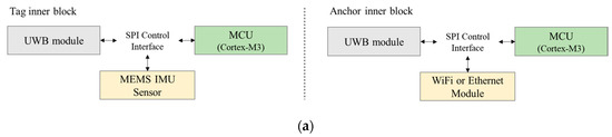
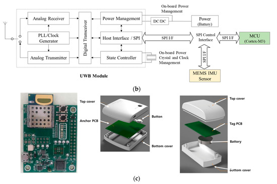
Figure 1.
(a) Process of tag of UWB and MEMS IMU and anchor of UWB/WiFi (or Ethernet), (b) process of UWB module, and (c) UWB sensor board of PCB assembly and anchor/tag design.
2.1. Positioning Tag and Anchor Based on UWB and MEMS IMU Sensor
Herein, a position tracking system is proposed in which the UWB communication module and the MEMS IMU sensor are integrated, as shown Figure 1b; the positioning tag consists of the UWB module [8], MEMS IMU sensor, MCU, and battery module. The MEMS IMU sensor is removed while either Wi-Fi or Ethernet module is included for the anchor, because it is installed on a fixed position and does not need to measure the position data [9,10]. In particular, the UWB modules [8] of the tag and anchor transmit signals between each other to measure the transmission time for estimating the distance between the tag and anchor. The MEMS IMU sensor provides the positioning calibration information on the basis of the accelerometer, angular velocity meter, geomagnetic meter, and altimeter. The tag, which is a moving node, is attached to a moving tool to measure the three-dimensional position of the tool and to deliver the coordinate information to the anchor, while notifying the operator as to whether the tool is performing the correct operation through alarming via an LED lamp. The anchor is installed in a fixed position and determines the distance between the tags and collects position data and alarm information from multiple tags. Figure 1c shows the UWB sensor board of the PCB assembly that we implemented and the design of the tag and anchor.
2.2. MEMS IMU Positioning Algorithm
The MEMS IMU sensor is an inertial sensor with Gyroscope, Accelerometer, and Magnetometer for measurements on three axes (Roll , Pitch , and Yaw ). We apply the MEMS IMU positioning algorithm by Yao [11]. The errors of speed and acceleration data measured by an IMU sensor are complemented by a UWB communication system, which makes the position measurement accurate. A tag sensor of UWB, accelerometers and gyros are mounted on the platform body of B frame and 3 anchors of UWB are located on any positions.
Given that and are the initial platform position and velocity to E frame, the position and the velocity for the platform motion to an indoor positioning coordinate frame (E frame) can be obtained by the computable accelerations for a local navigation coordinate frame (N frame).
Here, is computed by the following inertial navigation formula;
where is the measured body accelerations and is the gravity vector. is the computed translational velocity of the platform and is the angular velocity vector representing the transport rate vector from the EGI (Earth-Center-Inertial) frame (I frame) to the navigation coordinate frame (N frame).
is the measured gyro output. is a 3 × 3 direction cosine matrix computed from and ,
which represents the attitude of I frame for N frame and represents the transported B frame for I frame.
where
Here, by the earth’s rotation rate . () are the latitude and longitude of motion platform. By using these equations, we compute Euler angles of roll , pitch , and yaw and the position and velocity on N frame, as shown in Figure 2.
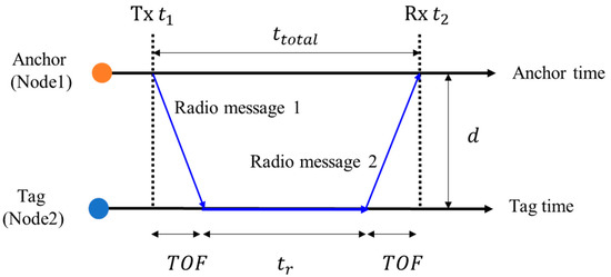
Figure 2.
Positioning principle in the two-way ranging (TWR) system.
2.3. UWB Positioning Algorithm
The two-way ranging (TWR) method [12,13,14] was developed to calculate the distance between two nodes by measuring the turnaround time of a pulse transmitted between the two nodes in which an Anchor node (Node 1) sends the pulse to a Tag node (Node 2) that transmits the pulse back to Node 1, and then by subtracting the processing time at Node 2, as shown in Figure 2.
In general, the moving distance of light is calculated by multiplying the speed of light and the measured time; thus, the distance between an anchor and a tag is expressed as and
where (Time of Flight) is
as shown in Figure 3. Here, represents the time required for a signal to be transmitted between an anchor. It is calculated by and is calculated by time stamps of Tx and of Rx and the response time . In addition, refers to the time required for a tag (Node 2) that has received the pulse signal to transmit the signal back. The TWR method has the advantage of simplifying the system through accurate positioning without synchronizing the nodes.
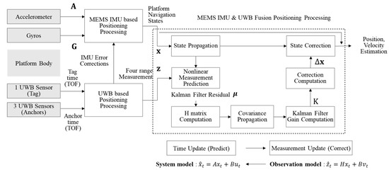
Figure 3.
Extended Kalman filtering process for integrated positioning by MEMS IMU and UWB.
Such wireless communication-based distance measurement is difficult to accurately recognize positions when the distance errors occur due to obstacles or changes in the indoor environment. Typical trilateration localization methods to reduce the distance measurement error can be used by topology [15], probability [16], confidence [17], and geographical similarity [18]. We used the confidence-based distance compensation trilateration localization method [17] to calculate the distance between 3 anchors and a target tag.
Firstly, we selected the fixed positions of 3 anchors: . The distances between 3 anchors and a tag can be computed by TOFs in Equation (1) and they satisfy the condition; for all . Here, the intersection points for the th anchor and th anchor can be derived from the simultaneous equation.
and
where . and are defined by
The distance of an anchor and a tag is updated to the new distance by the Cramr–Rao lower bound (CRLB) of TOF estimate and the confidence interval .
where
Given the positions of 3 anchors , radii of circles of them, and intersection points of anchors in Equation (4), the optimal intersection point can be selected by the following inequality equation.
The optimal intersection points for 3 anchors are obtained by the above method, then the position of target tag node is calculated by the centroid-based trilateration.
By changing the position of 3 anchors, the position of the target tag node can be computed by the above method.
2.4. EKT-Based MEMS IMU and UWB Integrated Positioning Algorithm
Integrated positioning algorithms of MEMS IMU and UWB sensors have been studied by using various Kalman filters, such as the extended Kalman filter [11,19] and complementary Kalman filter [20,21]. We applied Yao’s integrated positioning algorithm with the extended Kalman filter (EKT) [11]. The Kalman filter of a recursive filter estimates the state of a linear dynamic system containing noises that can recursively process the measurement data containing measurement noises, thus being widely used across various fields, including computer vision, robotics, and radar. As shown in Figure 3, the extended Kalman filter consists of five steps, largely comprising a step for predicting the current state and a step for estimating a more accurate value, including the measurement value [6].
We consider a 2D positioning frame for a platform that moves on an x-y plane with a body-mounted IMU and an UWB tag sensor. This means that two orthogonal accelerometers measure platform body acceleration on the x and y axes on the fixed E frame, and measure body angular velocity on the I frame with one gyro along the z axis. The state variables consist of position errors, velocity errors, and attitude angle errors and additional state variables for IMU sensors consists biases () of accelerations and gyros and misalignment errors. Among them, 8 state error variables can be defined [11], as follows;
where
By applying the small perturbations in the IMU positioning system, the error dynamic equation can be derived by the state-space form.
Here, the 8 × 8 sparse state-space matrix on any time can be defined by
where and are computed by the error of body accelerations and biases to the yaw on z axis as the following.
Next, the state-space parameter is a vector for gyro measurement defined by
where are gyro angle random walk (ARW) and gyro rate random walk (RRW) and are accelerometer biases stabilities. are computed by the accelerometer noises , to the yaw on the z axis, as follows.
are and . . are derived from Equation (2).
is the error of the angle velocity to the bias on the z axis; .
The range measurement and estimated rand measurement for 3 anchors of UWB can be defined by the Euclidean distance of anchors and a target tag platform including an anchor height and the measurement noises as follows:
where
The extended Kalman filter residual μ, the error between two range measurements , can be approximated by the gradient matrix and the state variables as follows:
The position and velocity of platform are estimated from the platform and navigation state variable from IMU sensors and the range measurements of 3 anchors of UWB sensors, as shown in Figure 3.
Let us take a closer look at the positioning process by EKT (Extended Kalman filter) that linearizes the state equation, as shown in Figure 4. EKT assumes the differentiability of a state transition function instead of the model linearity. There is a closed-form expression that the estimated state can be computed by a nonlinear function of the previous state , control , noise , and time .
The Jacobians of the predicted state to the previous state and the noise take simple forms when the noise goes linearly into the state update equation. In EKT, the measurement can be computed by a nonlinear function of the state and the measurement noise .
Here, are differentiable. In a sensor module, the position data measured at time contain noise components, which interfere with signal analysis. Therefore, to predict the estimated value for which noise components have been removed, the near-optimal Kalman gain is computed to predict in the EKT.
is the residual covariance; . The updated state estimate and covariance estimate can be expressed as
where is the measurement residual; .
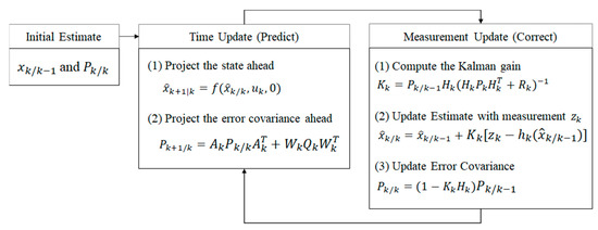
Figure 4.
Positioning process with extended Kalman filter.
Here, and represent the predicted state estimate and the predicted covariance estimate, respectively, as follows:
and are the state transition and state variable matrices defined to be Jacobians. and are the covariance matrix of the system and the measurement noise, respectively.
The final estimated value is predicted by multiplying an appropriate weight on the basis of with the predicted value and the measured value , followed by summing the two values, while is inversely proportional to the measured noise component, . Specifically, as the measured noise component becomes greater, decreases, and the rate at which is reflected in is decreased. It can be seen that the predicted error covariance, , is proportional to the system noise component, , and that is proportional to . Therefore, is proportional to . In other words, an increase in signifies that the reliability of is decreased, in which the components of the measured value are considerably reflected when predicting [6].
3. Experimental Results by Unit Testing
In this chapter, for evaluating the basic performance of the proposed positioning system, a basic telecommunication test, a LOS (line of sight) test, a non-LOS (NLOS) test, and a stopping test in an anechoic chamber were conducted indoors and outdoors.
3.1. Basic Telemmounication Test
A basic telecommunication test was conducted in various places including indoor, hallway, and outdoor areas, as shown in Figure 5. The experiment examined whether multiple anchors installed in a fixed position of each place effectively monitor the coordinate values of immovable or moving tags. The experimental result showed that the packet with accurate position coordinate values is received normally.
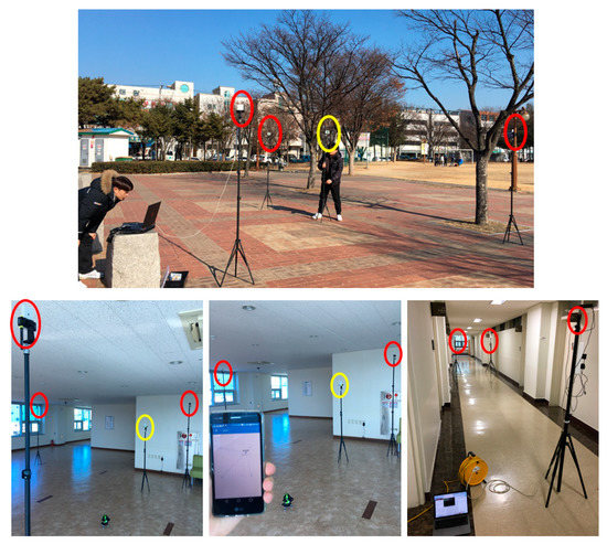
Figure 5.
Communication test in indoor and outdoor spaces with a tag (yellow circle) and 3 anchors (red circles).
3.2. LOS Test and Non-LOS Test
An LOS test was conducted after verifying the communication function between the anchor and node. Our LOS test installed three anchors in an indoor space without obstacles and we repeatedly measured the coordinates of 16 fixed positions for a tag along the x-, y-axes, as shown in Figure 6. The results of the repeated LOS and NLOS tests are presented in Table 1. All of the errors in indoor spaces were within ±200 mm.

Figure 6.
LOS environment test for measuring the coordinates of 16 fixed positions for a tag (yellow circle) based on 3 anchors (red circle; A1, A2, A3) installed in an indoor space without obstacle.

Table 1.
Indoor LOS and NLOS measurement data.
After the LOS test, an NLOS test was conducted to inspect the positioning performance in an indoor space with obstacles. In this experiment, the position coordinates of four tags in the indoor space were repeatedly measured. From Table 1, the measurement errors in the NLOS environment were slightly higher than those in the LOS environment, as predicted. Average measurement errors of LOS and NLOS tests are out 0 mm. However, a lot of tests for various indoors allows the average errors to approach 0 mm.
3.3. Anechoic Chamber Test
Lastly, the measurement test was conducted in an anechoic chamber. As shown in Figure 7, four anchors were installed at a 5 m interval in the length, width, and height directions, and the position of tags were repeatedly measured from four locations in the chamber.
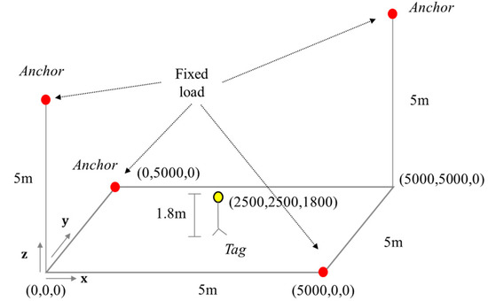
Figure 7.
Anechoic chamber test (a yellow circle represents a tag and red circles represent anchors).
The results of the stopping test in an anechoic chamber are presented in Table 2. The tags were installed to be fixed on a tripod. Measurement errors occurred on average 55.75 mm and 57 mm in the x- and y-axes directions, but on average 144.25 mm in the z-axis direction, slightly more than the x- and y-axes direction.
Table 2.
Measurement error for an immovable target.
4. Experimental Result of the Position Tracking System and Discussion
Following the measurement testing at a fixed position, the experimental results of a moving object are explained in this chapter. This experiment was conducted in an indoor anechoic chamber and the actual working environment.
4.1. Position Tracking Experiment in Anechoic Chamber
For this experiment, four anchors were installed at a 5 m interval in the length, width, and height directions, as shown in Figure 8. The position was repeatedly measured by controlling the movement of tags in a cubical space, during which the tags were controlled by being installed on a triaxial Cartesian robot. The results of measuring the position of tags moving, as shown in Figure 9, along the triaxial robot, are presented in Table 3. In this experiment, the position tracking was accurate in the x-axis and y-axis directions, but the positioning error in the z-axis direction was large.
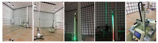
Figure 8.
Electromagnetic anechoic chamber test environment.
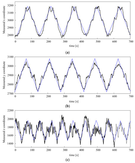
Figure 9.
Repetitive moving measurement data; (a) x, (b) y, and (c) z axes. The blue dot line represents the moving curve of the triaxial Cartesian robot along the reference coordinate.
Table 3.
Measurement data of orthogonal reciprocating motion using testbed.
Therefore, a moving average (MA) filter, Kalman filter [7], and our extended Kalman filters (EKT) were applied to the positioning data for improving the accuracy of positioning coordinates. Specifically, the MA, Kalman filter, and extended Kalman filter were applied to the measurement data after placing the tag on the reference coordinate (2700, 2700) on the fixed z axis. The measurements were taken for approximately 380 times to obtain reliable data; the results are shown in Figure 10.
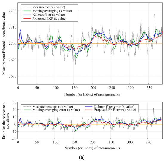
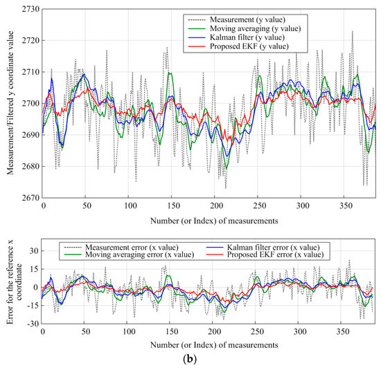
Figure 10.
Measurement results and error for the reference coordinate (2700,2700) using Moving Average filter (green line), Kalman filter [7] (blue line), and proposed EKF (red line) for (a) x-axis and (b) y-axis.
The figure shows the results of applying the MA, Kalman filter [7], and our EKT to the measurement data of moving nodes in an indoor space where multiple anchors are installed, and it can be observed that the position measurement error is significantly reduced when both types of filters are applied. The statistical results of the 380 measurements, as shown in Figure 10, are presented in Table 4; From these results, we found that our ETK-based method had less errors of 7.6 mm and 13.3 mm on the x and y axes compared to the MA method and also had less errors of 4.2 mm and 7.8 mm on the x and y axes compared to the Kalman filter method [7]. According to the numerical data, the application of the extended Kalman filter produced a smaller positioning error, which also can be confirmed through the graphical data.
Table 4.
Measurement data from sensor units and filtering results.
4.2. Position Tracking Experiment in Anechoic Chamber
Lastly, an experiment was conducted to examine the positioning accuracy for a tool in the actual automobile assembly process at an automobile repair shop, which resembles the real automobile assembly site. The fixed anchors were installed on four posts of the lift, and the tags were attached to the tool to measure its moving path, as shown in Figure 11. For displaying the current position of the tool operating in an automobile model, an application was developed for operation monitoring to display the position of the tool, as shown in Figure 12.
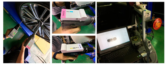
Figure 11.
Tool position tracking experiment in real working environment.
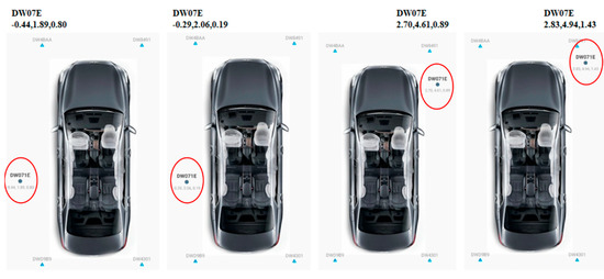
Figure 12.
Monitoring display of the position of the tool (red circle).
4.3. DAA(Detection and Avoid) Experiment
The UWB central frequency band used practically in the development product is 4492.8 MHz, which is included in the technical criteria of the existing frequency band and the changed frequency band. However, changes in radio frequency and UWB-related laws act as unexpected variables in development. The mean power density, including antenna absolute gain, is −70 dBm/MHz or less. IAT (Interference Avoidance Technology) reduces the amount to less than −70 dBm/MHz within two seconds and avoids it within 2 s if it detects signals from other radio stations greater than −61 dBm during operation.
Spectroscopic analysis shows that the BW (Band Width) was wider than the set 499.2 MHz, as well as signals in addition to BW. If signals were emitted from BW other than 3.735–4.8 GHz BW, the UWB radio frequency band was used by adjusting the register value of DW1000. After BW adjustment, we conducted a wire test and anaerobic radiation test through SMA connector wire. The final test conducted through a spectrum analyzer confirmed that it was within the frequency range in the regulation.
5. Conclusions
In this study, the UWB and MEMS IMU integrated positioning method was proposed for a system for accurately identifying and monitoring the position of work tools which are used in the assembly process of automobile production. Our method measures the accurate position, velocity, and attitude through a MEMS IMU sensor that is derived from the inertial navigation formula in 3 coordinate frames of indoor positioning frame (E-frame), local navigation frame (N frame), EGI frame (I-frame). Then, we computed the distance between an anchor node and a tag node by the TWR method. Here, we used the confidence distance compensation trilateration localization method to prevent the distance error by obstacles or changes in the indoor environment. Our method used the improved EKR by the error dynamic equation derived from 8 × 8 sparse state-space matrix, for the integrated positioning algorithms of MEMS IMU and UWB sensors. We compared our method to the previous UWB and MEMS IMU positioning method-based moving averaging filter and Kalman filter [7]. The results verified that our method has less errors (4.2 mm~13.3 mm) than the previous methods. Furthermore, we verified that the bandwidth is wider than 499.2 MHz and it is within the regularized frequency range, through DAA experiments. Also, we developed to monitor the accurate position of a work tool operating in an automobile model. Recently, the wireless positioning in the IoT has been researched much for indoor location identification [22,23]. Thus, we intend to study the applicability of the wireless positioning in the IoT for the future works.
Author Contributions
Conceptualization, S.-G.K. and S.-H.L.; methodology, S.-G.K., O.-J.K., K.-R.K. and S.-H.L.; software, S.-G.K. and S.-H.L.; validation, O.-J.K. and K.-R.K.; formal analysis, S.-H.L.; investigation, S.-G.K. and S.-H.L.; resources, S.-G.K.; data curation, S.-G.K.; writing—original draft preparation, S.-G.K. and S.-H.L.; writing—review and editing, O.-J.K. and K.-R.K.; visualization, S.-H.L.; supervision, K.-R.K.; project administration, K.-R.K. and S.-H.L.; funding acquisition, K.-R.K. and S.-H.L. All authors have read and agreed to the published version of the manuscript.
Funding
This research was supported by the Basic Science Research Program through the National Research Foundation of Korea (NRF) funded by the Ministry of Education (2020R1I1A306659411, 2020R1F1A1069124), and also supported by the MSIT (Ministry of Science and ICT), Korea, under the ITRC (Information Technology Research Center) support program (IITP-2021-2020-0-01797) supervised by the IITP (Institute for Information & Communications Technology Planning & Evaluation).
Institutional Review Board Statement
Not applicable.
Informed Consent Statement
Not applicable.
Conflicts of Interest
The authors declare no conflict of interest.
References
- Ok, C.H.; Kim, D.S.; Gong, J.S.; Seo, Y.H. Study on integrated storage systems for automobile production. J. Korea Soc. Simul. 2012, 21, 91–101. [Google Scholar] [CrossRef][Green Version]
- Gilchrist, A. Industry 4.0: The Industrial Internet of Things; Apress: New York, NY, USA, 2016. [Google Scholar]
- Khan, A.; Turowsk, K. A perspective on Industry 4.0: From challenges to opportunities in production systems. In Proceedings of the International Conference on Internet of Things and Big Data, Rome, Italy, 23–25 April 2016; pp. 441–448. [Google Scholar]
- Gezici, S.; Tian, Z.; Giannakis, G.B.; Ko-bayashi, H.; Molisch, A.F.; Vincent Poor, H.; Sahinoglu, Z. Localization via ultra-wideband radios. IEEE Signal Process. Mag. 2005, 22, 70–84. [Google Scholar] [CrossRef]
- Hu, J.; Zhu, Y.; Wang, S.; Wu, H. Energy efficient, reconfigurable, distributed pulse generation and detection in UWB impulse radios. In Proceedings of the IEEE International Conference on Ultra-Wideband, Vancouver, BC, Canada, 9–11 September 2009; pp. 773–777. [Google Scholar]
- Alonge, F.; Cucco, E.; D’Ippolito, F.; Pulizzotto, A. The use of accelerometers and gyroscopes to estimate hip and knee angles on gait analysis. Sensors 2014, 14, 8430–8446. [Google Scholar] [CrossRef] [PubMed]
- Kwon, S.G. Position tracking system based on UWB and MEMS IMU. J. Korea Multimed. Soc. 2019, 22, 1011–1019. [Google Scholar]
- Mallat, A.; Vandendorpe, L. Joint estimation of the time delay and the clock drift and offset using UWB signals. In Proceedings of the IEEE International Conference on Communications, Sydney, Australia, 10–14 June 2014; pp. 5474–5480. [Google Scholar]
- Yang, L.; Giannakis, G.B. Ultra-wideband communications: An idea whose time has come. IEEE Signal Process. Mag. 2004, 21, 26–54. [Google Scholar] [CrossRef]
- Intrieria, E.; Giglia, G.; Gracchi, T.; Nocentini, M.; Lombardi, L.; Mugnai, F.; Frodella, W.; Bertolini, G.; Carnevale, E.; Favalli, M.; et al. Application of an ultra-wide band sensor-free wireless network for ground monitoring. Eng. Geol. 2018, 238, 1–14. [Google Scholar] [CrossRef]
- Yao, L.; Andy Wu, Y.-W.; Yao, L.; Liao, Z.Z. An integrated IMU and UWB sensor based indoor positioning system. In Proceedings of the International Conference on Indoor Positioning and Indoor Navigation (IPIN), Sapporo, Japan, 18–21 September 2017. [Google Scholar]
- Duru, A.; Sehirli, E.; Kabalci, I. Ultra-wideband positioning system using TWR and lateration methods. In Proceedings of the 4th International Conference on Engineering & MIS, Istanbul, Turkey, 19–20 June 2018; pp. 1–4. [Google Scholar]
- Conti, A.; Dardari, D.; Guerra, M.; Mucchi, L.; Win, M.Z. Experimental characterization of diversity navigation. IEEE Syst. J. 2014, 8, 115–124. [Google Scholar] [CrossRef]
- Lian Sang, C.; Adams, M.; Hörmann, T.; Hesse, M.; Porrmann, M.; Rückert, U. Numerical and experimental evaluation of error estimation for two-way ranging methods. Sensors 2019, 19, 616. [Google Scholar] [CrossRef] [PubMed]
- Misra, R.; Shukla, S.; Chandel, V. Lightweight localization using trilateration for sensor networks. Int. J. Wirel. Inf. Netw. 2014, 21, 89–100. [Google Scholar] [CrossRef]
- Lee, J.-H.; Kim, K.; Lee, S.-C. An efficient localization method based on adaptive optimal sensor placement. Int. J. Distrib. Sens. Netw. 2014, 10, 983618. [Google Scholar] [CrossRef]
- Li, J.; Yue, X.; Chen, J.; Deng, F. A novel robust trilateration method applied to ultra-wide bandwidth location systems. Sensors 2017, 17, 795. [Google Scholar] [CrossRef] [PubMed]
- He, G.; Li, L.; Lao, L. A localization algorithm based on geographical similarity of RSSI in wireless sensor networks. In Proceedings of the 2009 International Symposium on Computer Network and Multimedia Technology, Wuhan, China, 18–20 January 2009; pp. 1–5. [Google Scholar]
- Guosheng, W.; Shuqi, Q.; Qiang, L.; Heng, W.; Huican, L.; Bing, L. UWB and IMU system fusion for indoor navigation. In Proceedings of the 37th Chinese Control Conference (CCC), Wuhan, China, 25–27 July 2018; pp. 4936–4950. [Google Scholar]
- Li, X.; Wang, Y.; Khoshelham, K. A robust and adaptive complementary Kalman filter based on mahalanobis distance for ultra wideband inertial measurement unit fusion positioning. Sensors 2018, 18, 3435. [Google Scholar] [CrossRef] [PubMed]
- Liu, F.; Li, X.; Wang, J.; Zhang, J. An adaptive UWB MEMS-IMU complementary Kalman filter for indoor location in NLOS environment. Remote Sens. 2019, 11, 2628. [Google Scholar] [CrossRef]
- Silva, P.F.; Kaseva, V.; Lohan, E.S. Wireless positioning in IoT: A look at current and future trends. Sensors 2018, 18, 2470. [Google Scholar] [CrossRef] [PubMed]
- Pascale, F.; Adinolfi, E.A.; Avaglian, M.; Giannella, V. A low energy IoT application using beacon for indoor localization. Appl. Sci. 2021, 11, 4902. [Google Scholar] [CrossRef]
Publisher’s Note: MDPI stays neutral with regard to jurisdictional claims in published maps and institutional affiliations. |
© 2021 by the authors. Licensee MDPI, Basel, Switzerland. This article is an open access article distributed under the terms and conditions of the Creative Commons Attribution (CC BY) license (https://creativecommons.org/licenses/by/4.0/).