1. Introduction
The Phobos Sample Return Mission is an incipient phase of the Mars Robotic Exploration and Preparation 2 (MREP-2) programme [
1]. Due to the impact ejecta phenomenon described in [
2], the regolith from Phobos may contain up to 250 ppm in a concentration of particles coming from Mars’ Surface. As the robotic exploration of Phobos is easier and safer than Mars, this makes it the perfect candidate to understand the origins of the red planet.
Throughout history, there have been several attempts to explore the Martian moon Phobos, in the frame of the Phobos 1 and 2 missions organized by the former Union of Soviet Socialist Republics (URSS) [
3] and the Phobos-Grunt mission launched by Russia in 2011 [
4]. While Phobos 1 failed prematurely, Phobos 2 managed to observe Phobos, Deimos and Mars before suffering a fault that led to losing contact with the operation centre [
5]. Phobos-Grunt mission also encountered a failure in the early stages due to a programming error, which caused it to lose contact with the operation centre while it was on the Low Earth Orbit, later being destroyed as it descended uncontrolled in the Earth’s atmosphere [
4]. The European Space Agency (ESA) conducted a thorough study regarding a Phobos Sample Return Mission [
6], highlighting the main challenges of this type of mission and proposing a possible mission architecture that would involve also Russia, considering their previous experience with the Martian moon. However, the Phobos Sample Return Mission was put on hold, as now the main goal of the space industry is to bring samples directly from Mars in the frame of the Mars 2020 mission currently ongoing [
7]. Although the scientific community is focused right now on Mars’ exploration, Japan Aerospace Exploration Agency (JAXA) prepares the Martian Moons Exploration (MMX) having among its purposes to establish the origin of Mars’ natural satellites, as well as to bring to Earth regolith samples from Phobos’ surface [
8]. Currently, the mission is scheduled for launch in 2024 [
9].
National Aeronautics and Space Administration (NASA) is currently studying Mars under the Mars Exploration Program, providing information related to planet evolution, history of geological and climate processes that have shaped Mars through time and the potential to have hosted life (its biological potential) [
10]. A joint NASA-ESA mission is under development as part of NASA’s Mars Exploration Program to bring samples of Martian rocks and soil back to Earth. The Sample Return Mission is designed to continue the work of NASA’s Mars 2020 Rover. During the mission architecture, NASA is working on a Sample Retrieval Lander that would launch the retrieved samples into Mars orbit while ESA is working on an Earth Return Orbiter that would rendezvous with the samples in Mars orbit and bring them back to Earth. The foreseen launch date for the joint program is in 2026 and to touch Mars soil in 2028 [
11].
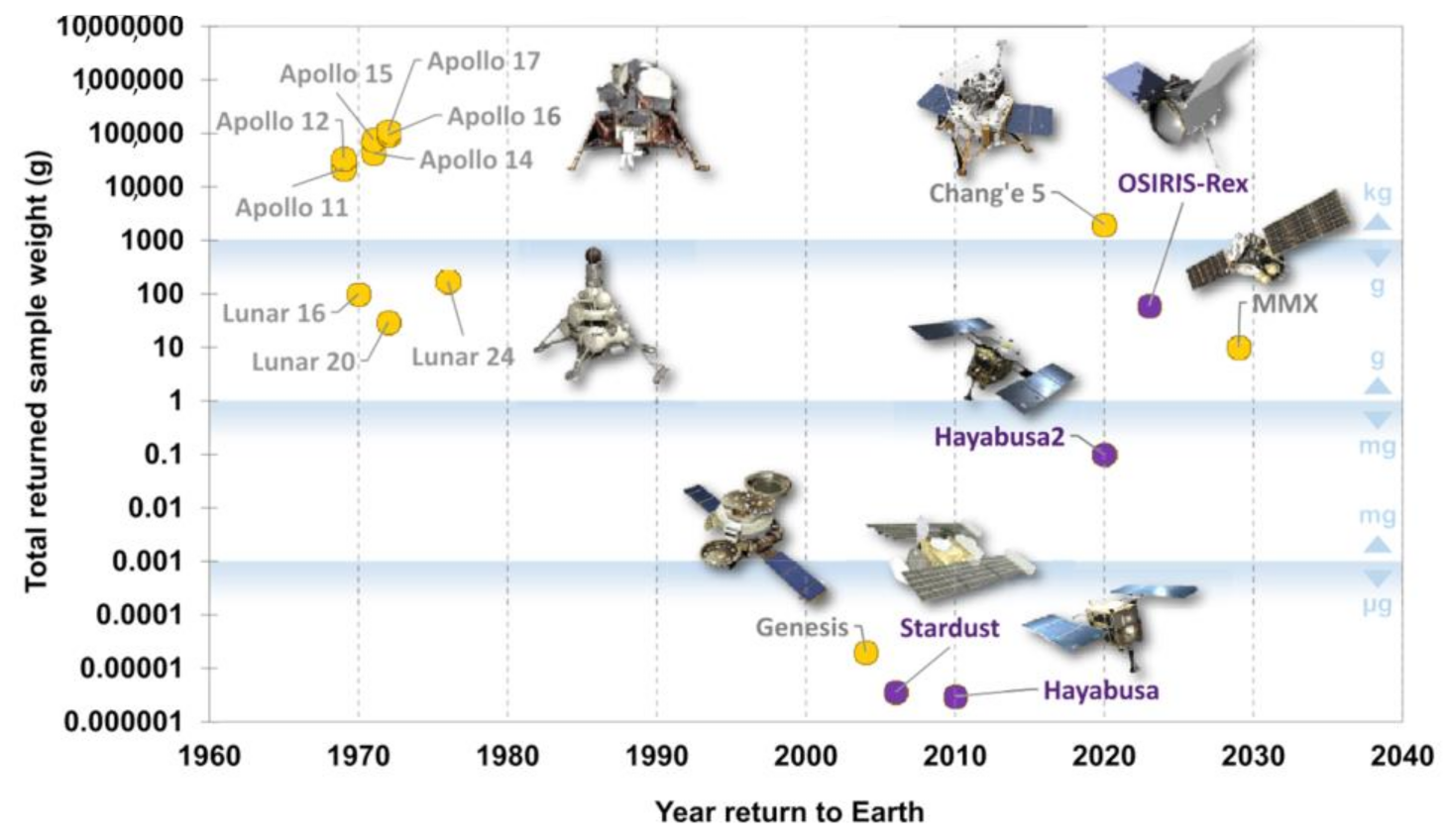
Sample Return Missions are an extremely valuable resource, both for the scientific community and society. The analysis of samples from other bodies in the Solar System can answer fundamental questions for humankind, as well as give an insight regarding their resources (ores, rocks, etc.) which could prove useful in the future. The idea of Sample Return Missions dates back to 1969 [
12], starting with the first steps made on the Moon. A year later, the former URSS performed the first sampling using remote-controlled equipment [
3], thus paving the way for future robotic exploration missions on other planetary bodies. A chronology of the Sample Return Missions is shown in
Figure 1.
In recent history, the Sample Return Missions that stand out as being successful are the two Hayabusa missions conducted by JAXA [
3], first to the Itokawa asteroid, and the second one to Ryugu, both celestial bodies being classified as NEO and potentially hazardous asteroids [
14,
15]. A third Sample Return Mission is on its way to Earth, NASA’s OSIRIS-REx mission to Bennu [
16].
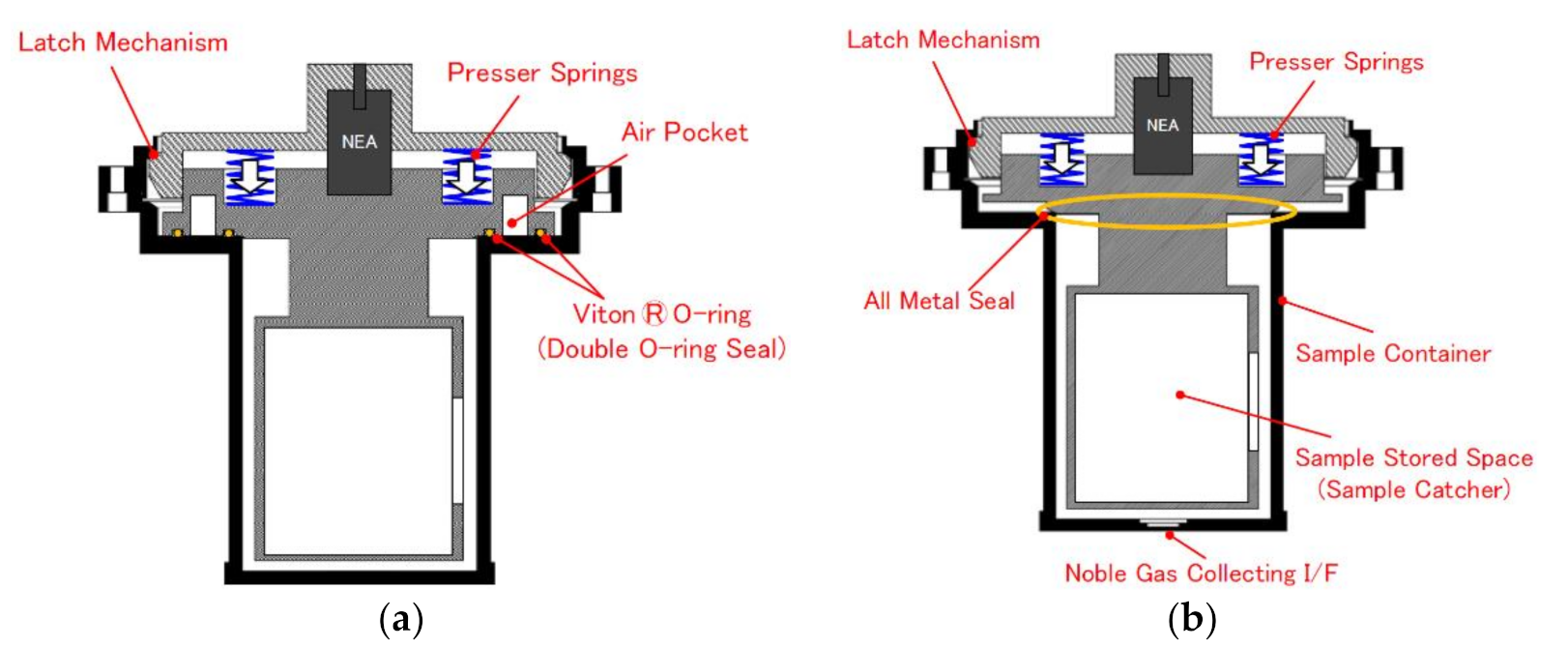
In the first Hayabusa mission, the sample containment system was featured with two Viton O-rings, which were replaced in the second mission with a metallic seal due to the fluorocarbon material of the sealing elements which can interact with organic molecules (either terrestrial or from the sample) [
17]. Although the Hayabusa concept (
Figure 2a,b) uses the same actuation means as in the case of the concept developed in this paper, it shall be stated that the seal proposed by JAXA requires a pretension force because the sealing elements are mounted axially. Moreover, the Hayabusa concept is based on a touch-and-go mission architecture, while the proposed sealing and closing system are designed for a sampling-by-landing mission.
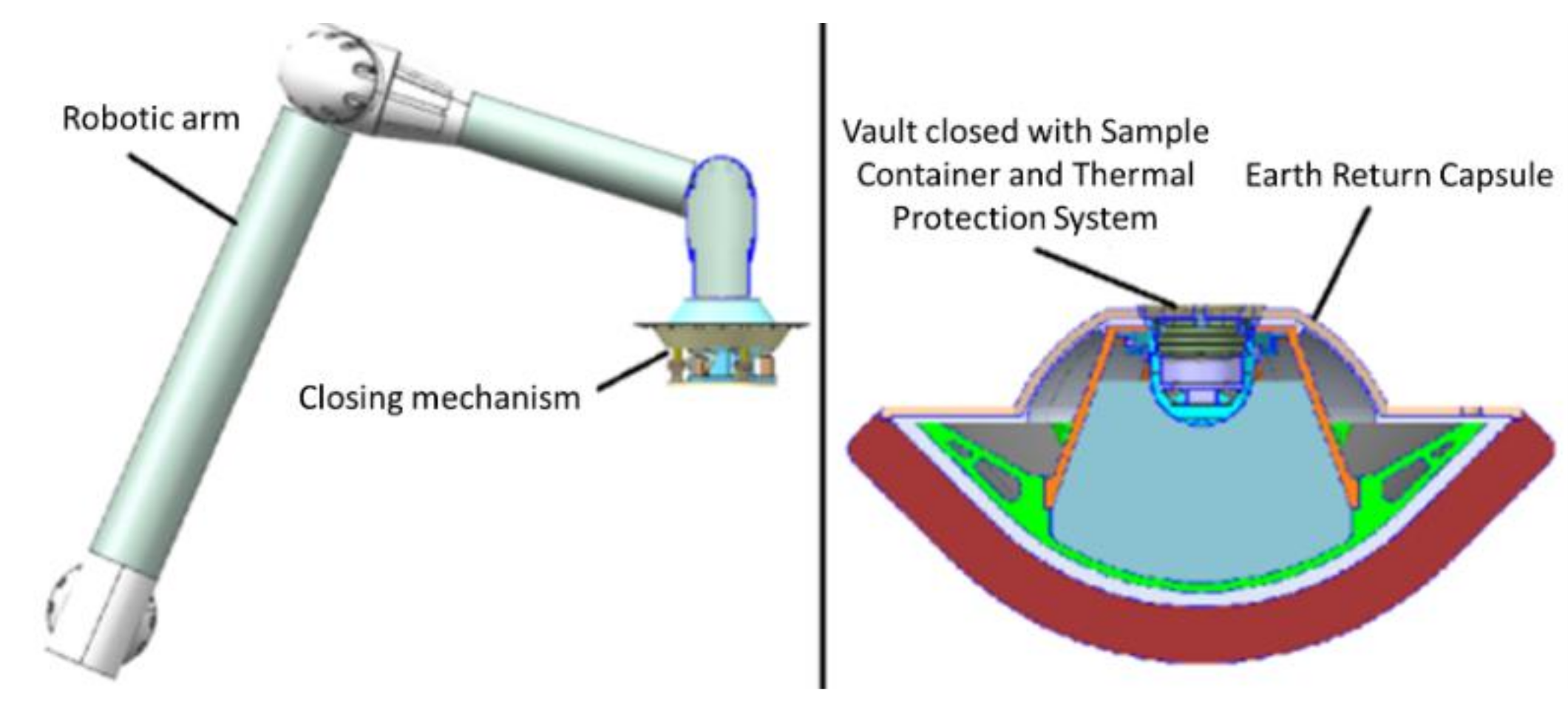
The closing force evaluation is one of the key aspects of the mission proposed under the MREP-2 programme. The current architecture presumes using a robotic arm with limited capacities in terms of force (maximum 40 N of pushing force), having a sampling tool at the end which is used to collect the regolith in a Sample Container (SC), as seen in
Figure 3a. After the regolith sampling, the vault is closed with the SC by pushing it with the necessary force using a closing mechanism, illustrated in
Figure 3b.
Considering the requirements for a Phobos Sample Return Mission, a special closing mechanism with mechanical actuators was designed under a project coordinated by ESA. The actuators are helical compression springs, and their characteristics and specifications were established based on the experimental data and motorization factors given by the ECSS-E-ST-33-01C standard [
19]. The closing mechanism, presented in
Figure 4, is physically separated from the SC after the closing operation, remaining on Phobos along with the Robotic Arm).
A set of requirements were used as input data for the development of the sealing and closing system. Several ones were considered as driving requirements when it comes to evaluating the necessary closing force to achieve the sealing and closing of the sample container vault, such as the ones presented in
Table 1. It is to be noted that, during the mission, the vault shall withstand operational and non-operational temperatures, however, the vault closing operations are performed when the vault is in the range of the defined operational temperature. Consequently, to determine the required closing force through tests, the operational temperature domain was considered, altogether with +/−5 °C margins according to ECSS-E-ST-33-01C.
The critical review of the technical requirements imposed by ESA consists in identifying their effects over the design, with respect to the optimal dimensioning of the components and the entire system. The first step was to determine the most suitable sealing technologies for this mission. This was achieved by performing a comprehensive trade-off analysis [
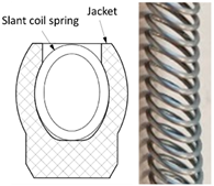
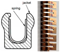
20] which considered a large number of factors and aspects relevant to the mission. The results of this trade-off concluded that the best sealing technology is the use of radial seals with a composite jacket and metallic spring energizer. To achieve redundancy, the vault design featured two sealing elements with different diameters.
2. Sample Containment and Closing System–Design Overview
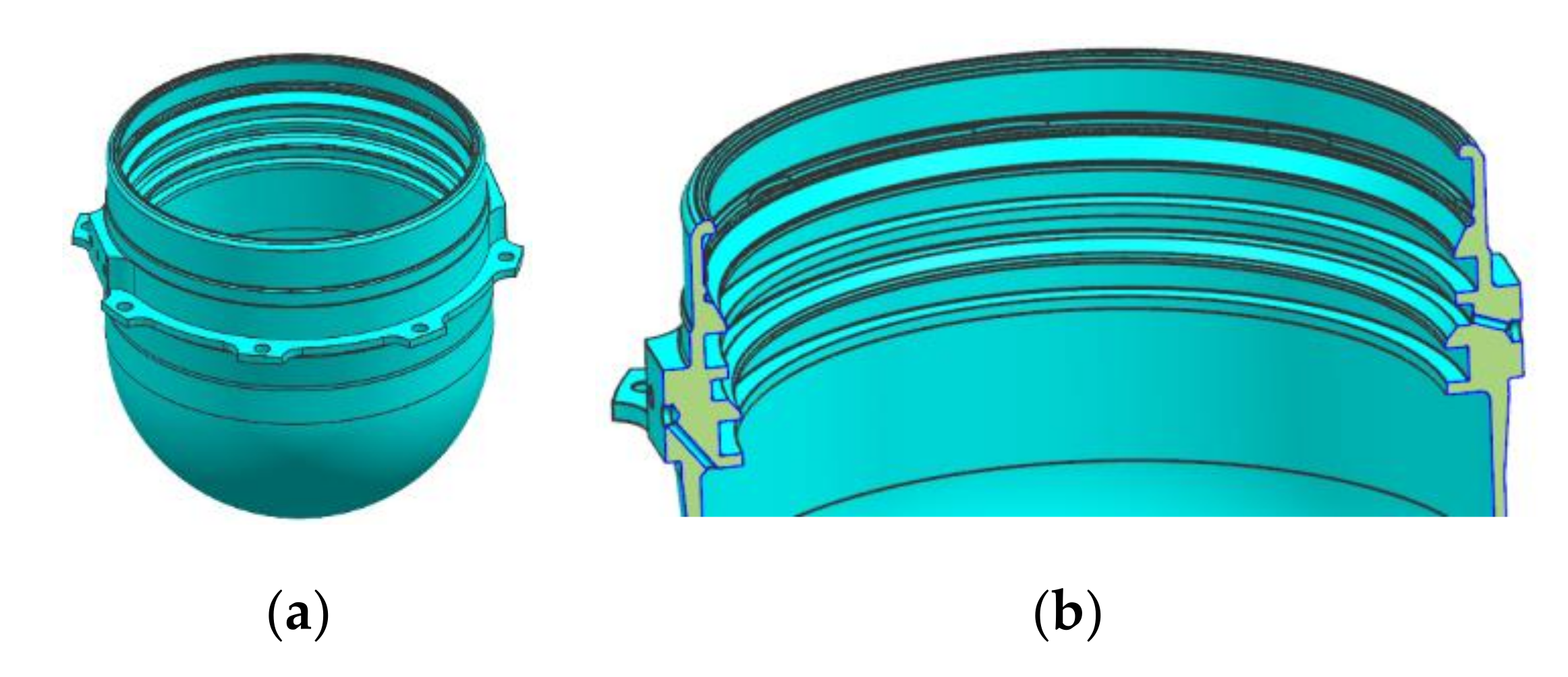
The vault is a metallic component that is placed inside an Earth Return Capsule (ERC,
Figure 5). Its outside geometrical shape is a consequence of the ERC interior space geometry defined by Airbus Defence and Space UK and also, specified by one of the requirements. On the outside surface, the Vault has a flange with several holes used to fix the Vault on the ERC internal structure. There are several circular grooves on the Vault’s inside. Two of these grooves are featured to mount the sealing elements and are closed type grooves. It is worth mentioning that these types of grooves were chosen due to the reasons of shape simplicity and reduced mass of the vault while accepting a more difficult mounting of the sealing elements, as well as their irreversible damage when removing them from the grooves. The other ones are foreseen to collect the regolith particles attached to the exterior surface of the SC to minimize the risk of deteriorating these surfaces when introducing the SC in the Vault. As a safety measure, all the grooves edges are also rounded to ease the passive alignment of the SC during the closing operation.
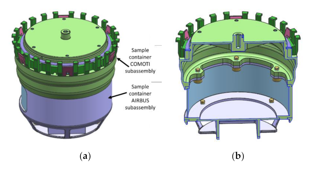
The Vault is sealed using the SC consisting of two mechanical subassemblies with different functional roles that were designed by, COMOTI and AIRBUS. COMOTI designed the upper part, highlighted with light green in
Figure 6 which assures the vault sealing. Airbus designed the lower part highlighted with grey in
Figure 6, which accommodates the sampled regolith.
The sealing surfaces of the Sample Container are featured with conical, rounded and cylindrical surfaces, without any sharp edges. Their purpose is to allow the initial interference between the surfaces and energization of the sealing elements [
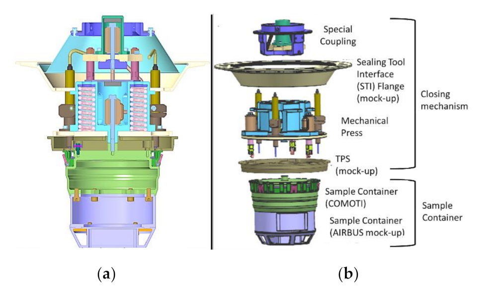
21] while inserting the SC inside the Vault and sealing the inner space of the Vault. These design particularities were the results of the closing force evaluation and they will be pursued in the following paragraphs of the paper. The Vault and the SC are closed using a dedicated mechanism called a Closing Mechanism, shown in
Figure 7. This device has two main subassemblies, a special coupling, designed to overcome the robotic arm misalignments (not included in the current paper) and a Mechanical Press (MP) which ensures the closing operation. The MP uses the force provided by the helical springs which are maintained in compression state and, by whose relaxation during the closing operation, the SC is pushed inside the Vault, thus achieving the tightness.
Following a trade-off made during the first phase of the project and presented in [
20], several sealing technologies were investigated and it was concluded that O-rings, gaskets, knife-edge and brazing (excluded in the end) could be reliable for the mission.
The three sealing technologies mentioned before were investigated once again in terms of the necessary force needed to achieve the tightness. The results indicated that the most suitable type of sealing element is radial sealing with a composite jacket and metallic spring energizer. As it was previously mentioned, the two sealing elements are placed on different diameters, as is depicted in
Figure 8. The image shows also the specific areas of the SC which get in contact with the sealing elements during the closing operation.
It shall be noted that the sealing elements described in this paper are custom made items designed and manufactured according to several requirements imposed by COMOTI. The two types of sealing elements are presented in
Table 2 and, from now on, they will be referred to as Type I (supplied from Trelleborg) and Type II (supplied from Saint-Gobain) seals. Both types of sealing elements are designed for radial sealing located in closed grooves–rod type.
3. Design and Manufacturing of the Testing Devices
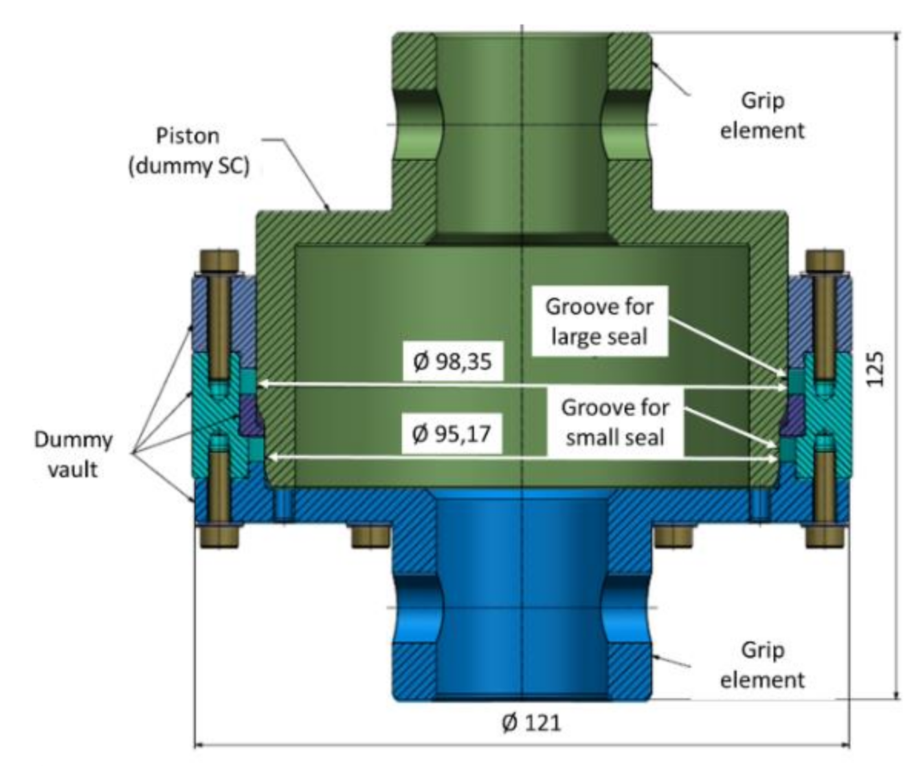
To define the optimal design, to characterize the engineering parameters and to gather data, a device representative of the vault and SC was designed and manufactured for this test. This partial breadboard (dummy) was used to measure the closing force and, after that, the results of the tests were used to optimize the design. The testing device is presented in
Figure 9.
As it was previously mentioned, the Vault (
Figure 5) was designed with closed grooves, however, to prevent the destruction of the sealing elements during the dismounting operation, the vault dummy was designed and manufactured with open grooves. The closing of the Vault is made by pushing the SC. The two sealing elements oppose by creating a resistant force during the Vault’s closing when they get in contact with the SC surfaces. At the end of the stroke, the seals are in contact with the cylindrical surfaces of the SC. Due to the axial symmetry of the Vault and SC, the opposing force is radial. The closing stroke of the Vault is approximately 8 mm.
The pushing force exerted on the SC has two components:
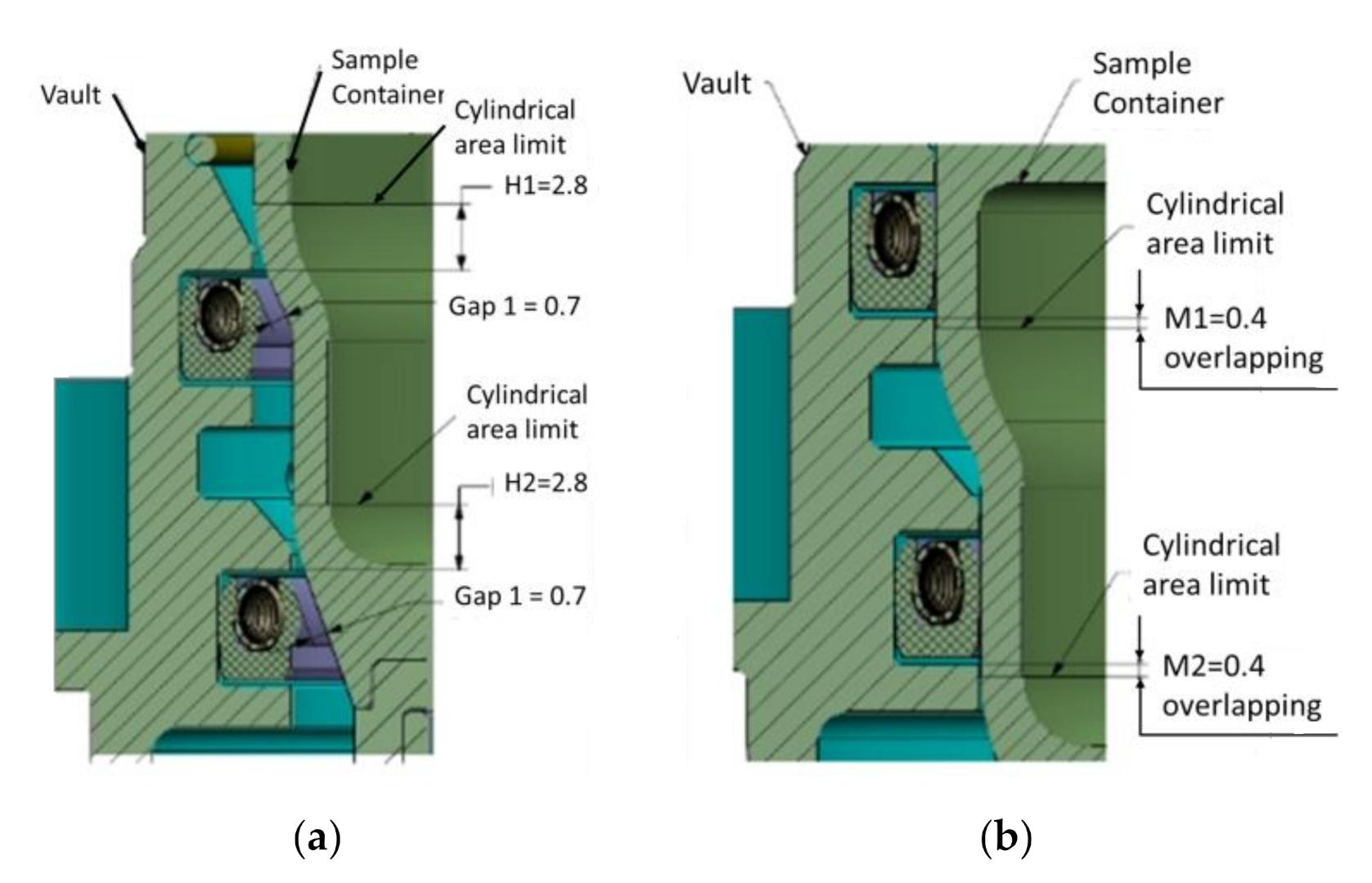
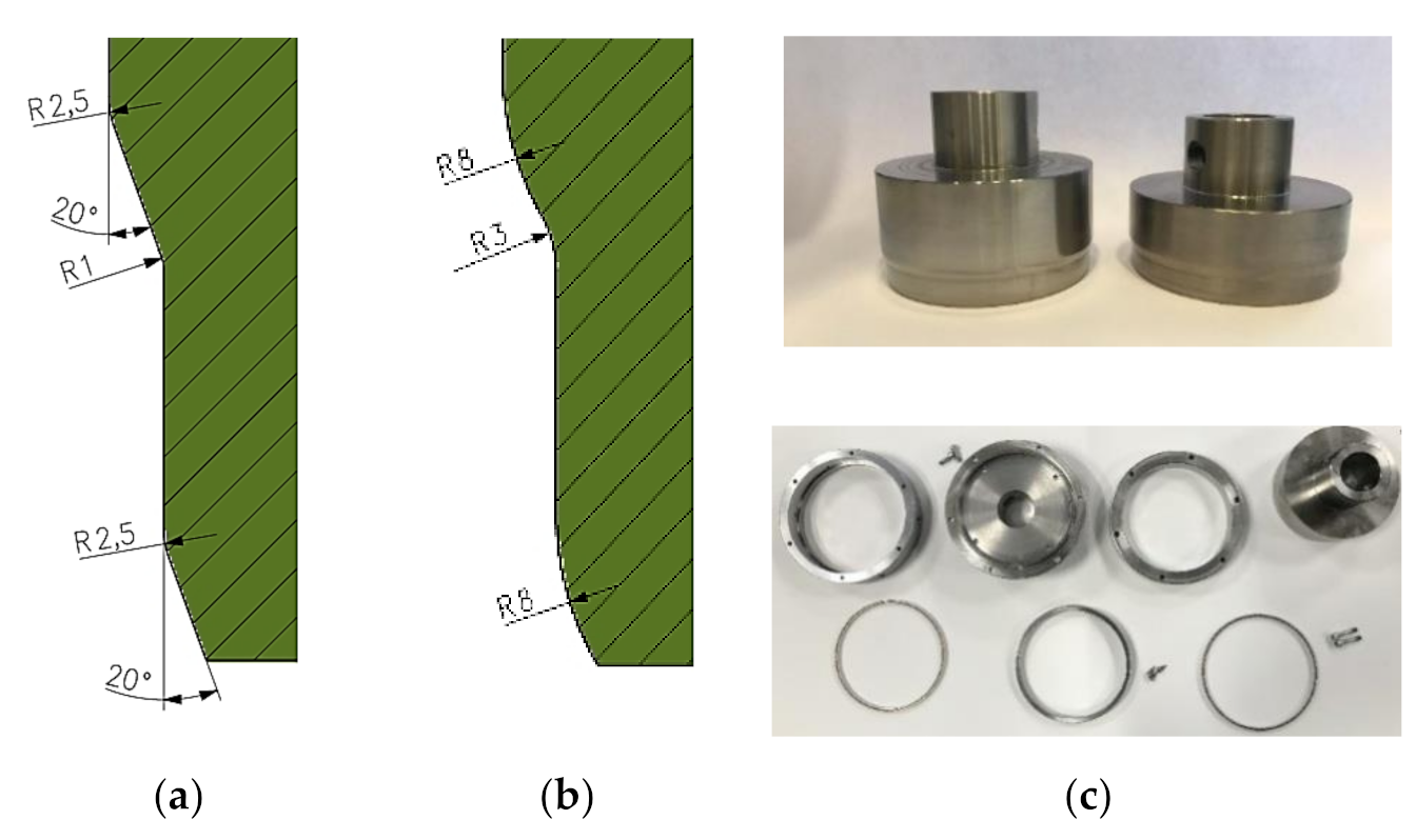
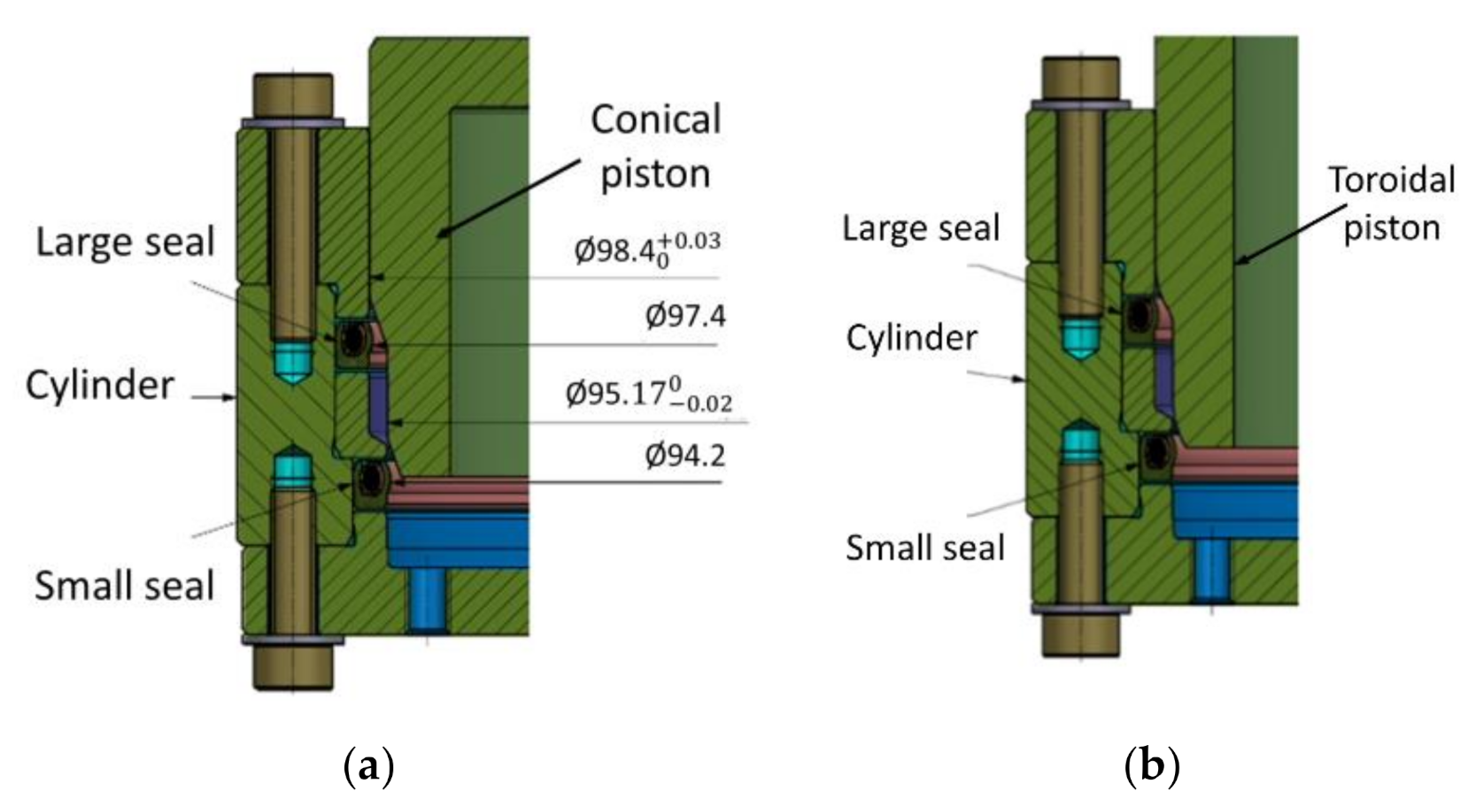
Two partial breadboards (dummies) for the SC were designed, manufactured and used to measure the closing force. The difference between them is represented by different geometrical shapes in the areas that ensure the enlargement of the sealing elements, namely conical (CO) and toroidal shape (TO). The difference is depicted in
Figure 10a,b and the manufactured parts (grade 5 Titanium alloy) are presented in
Figure 10c. Hereinafter, the vault dummy will be called cylinder and the SC dummy will be called piston.
The surface finish is an important feature when it comes to ensuring the Vault’s tightness. The sealing elements manufacturers recommended a roughness average (Ra) between 0.2 µm and 0.4 µm. Following the finishing process, the corresponding values have been obtained, making the test more suggestive. The roughness evaluation was performed with a MahrSurf PS 10 device (Mahr GmbH, Gottingen, Germany), over a distance of 10 mm with a 1 mm/s rate.
The sealing elements mounted in the cylinder have smaller inside diameters than those of the piston to achieve the necessary tightening for sealing when the piston is mounted in the cylinder. The evaluation of the necessary closing force was made for a stroke of 8 mm, corresponding to the insertion path of the Sample Container in the Vault during the closing operation, illustrated in
Figure 11.
When introducing the piston inside the cylinder (simulating the vault closing operation), the following phases take place:
In the start position the piston does not touch the sealing elements;
When moving the piston, it touches the sealing elements with the conical and rounded areas (
Figure 12);
When moving the piston up to 6 mm, the opposing forces are those needed to enlarge the sealing elements and the friction forces that occurred on the sealing elements;
After moving the piston, the sealing elements do not enlarge anymore and, until the end of the stroke, the forces opposing the movement of the piston are only the friction forces on the sealing elements.
It shall be mentioned that both the old and the new piston come first in contact with the two sealing elements simultaneously. The differences between the two pistons are only the areas that ensure the sealing elements enlargement.
5. Closing Force Measurement
Before starting to evaluate the closing force, an empty test (without seals) was performed (as presented in
Figure 13) to be sure that the contact/friction forces between the piston (sample container mock-up) and the cylinder (vault mock-up) are negligible. After the closing force evaluation tests were finished, another empty test was also performed.
5.1. Piston–Conical Shape
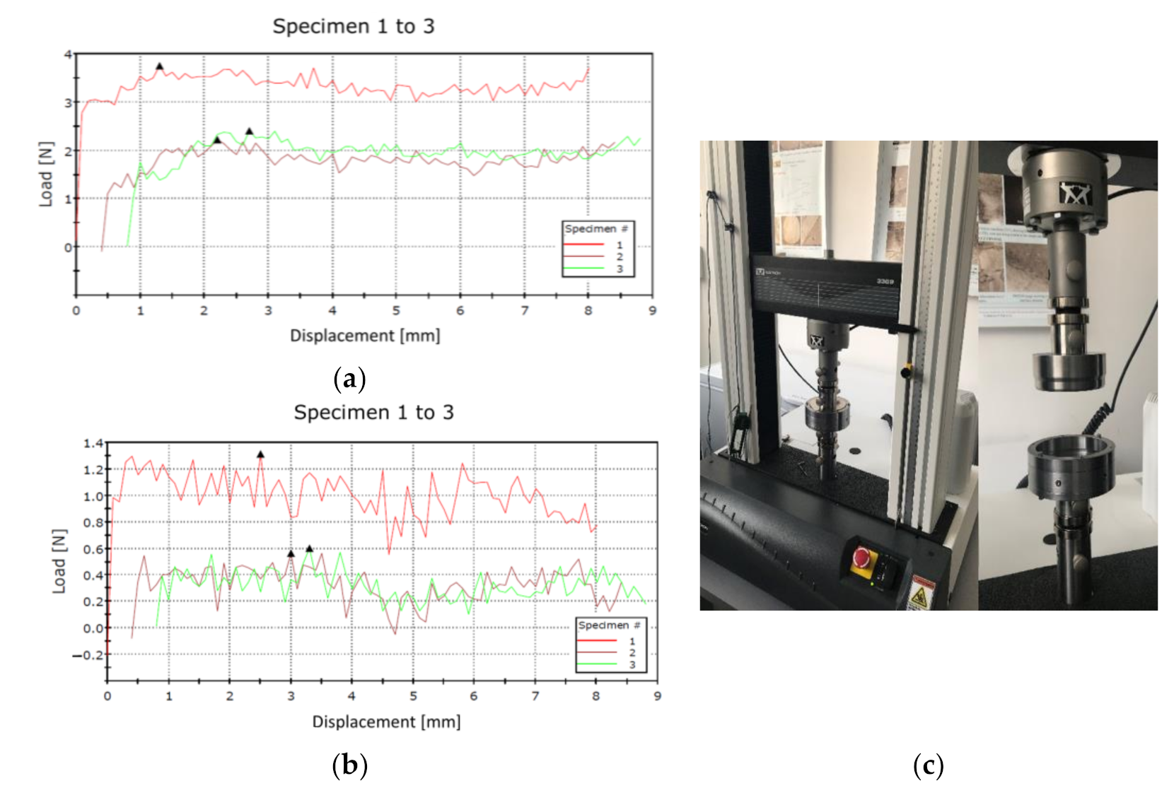
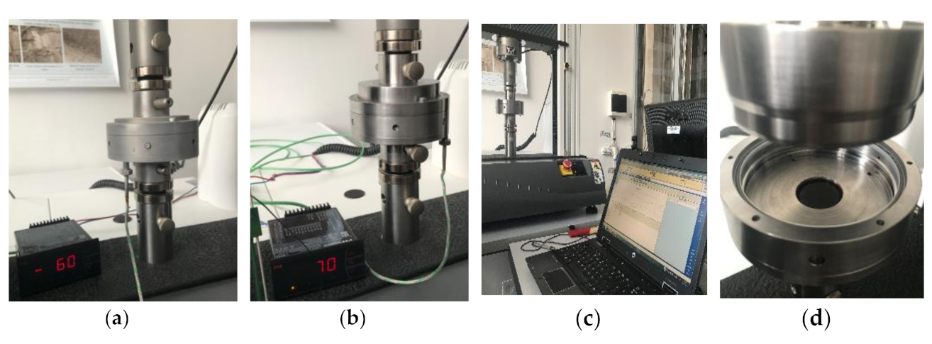
Following the initial empty tests, Type I and Type II seals were tested at the worst-case scenario (−65 °C), ambient temperature (+20 °C) and the highest possible temperature (+70 °C).
Figure 14 illustrates the testing set-up for both extreme temperatures and the thermocouple positioning.
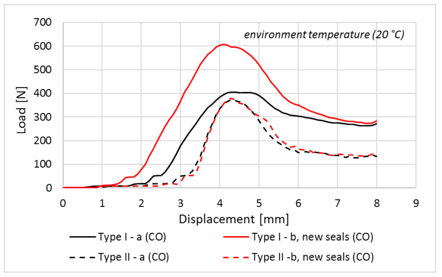
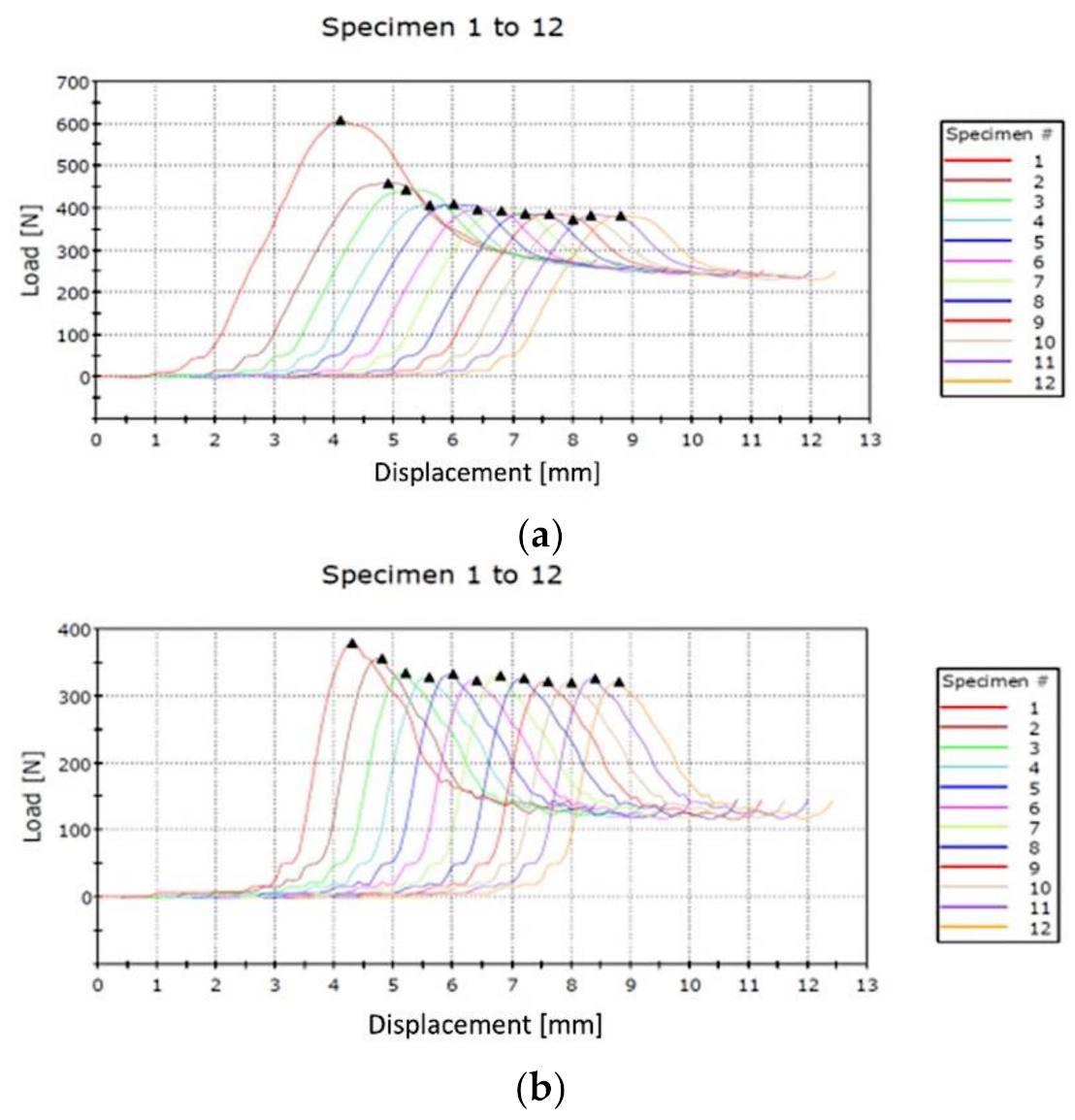
For each type of test/configuration, several determinations at 1-min intervals were made successively. The forces obtained decreased after each test because, when introducing the piston in the cylinder, the sealing elements are enlarged. After pulling out the piston, the sealing elements are free, but they do not come back immediately to the initial shape. Because of that, when performing the next closing, their enlargement is smaller and, thus, the necessary force is smaller. For the piston with conical shape (CO) tests were performed firstly and for each sealing element along with tests with both sealing elements mounted at the same time. In the following paragraphs, the term “new seal” will be used every time a sealing element is tested for the first time. Maximum obtained closing forces for each Type I and Type II seals at environment temperature (+20 °C) are marked in
Figure 15.
From the results presented in
Figure 15, the maximum measured values for the friction force at environmental temperature were extracted, respectively 608 N for Type I seal and 379 N for Type II seal, as shown in
Figure 16.
Considering the graph plotted in
Figure 16, it can be seen that the Type I seals that were individually tested (closing force evaluation for one seal), have a different behaviour than the new seals. The maximum force for Type I-b new seals (CO) configuration is around 608 N and the maximum force for Type I-a (CO) (individually tested) configuration is around 470 N. The Type II seals have almost the same behaviour and the maximum force is around 379 N. The force curves do not have the same starting point, where Type I-b new seals (CO) start at 1.7 mm, Type I–a (CO) start at 2.3 mm and Type II-a (CO) start at 3.1 mm. This is because there are some gaps between the piston/vault mock-up and the testing machine gripping devices. This aspect can be observed for all the graphs which are presented in this paper, but these gaps do not affect the maximum closing force determination.
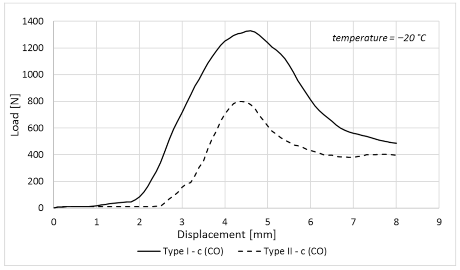
To analyse the temperature effect over the closing force, it was decided to perform a new test at −20 °C. After this test, it was identified that the force for Type I seals was 1330 N, while for Type II was 799 N (
Figure 17).
As expected, the closing force increased when the operating temperature dropped. Similar to the test performed at +20 °C, the graphs tendency is kept, Type I seals requiring higher forces than Type II. From
Figure 17, it can be observed that there is a difference of around 500 N between the maximum closing force for Type I seals and Type II seals.
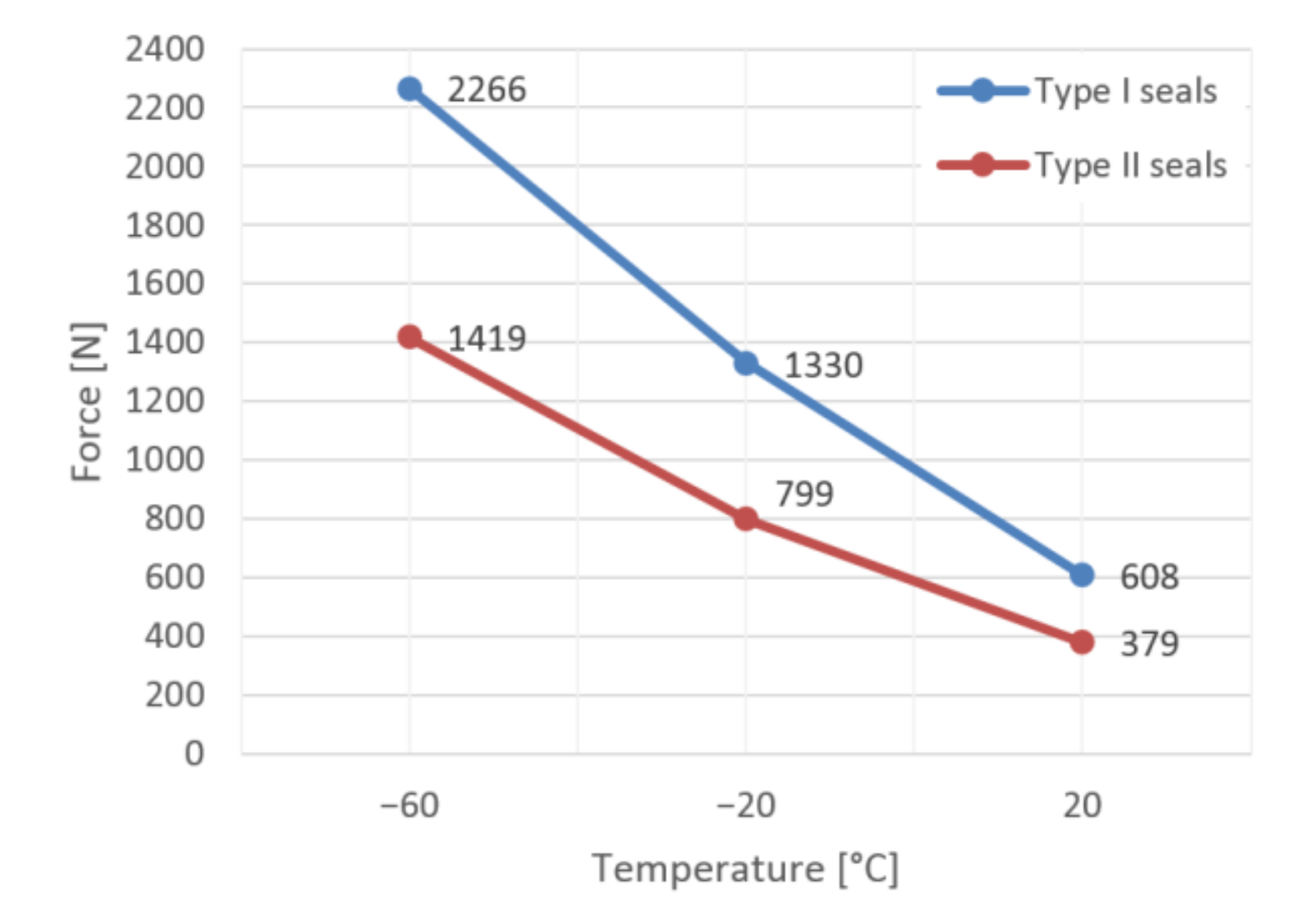
For a better evaluation of the temperature effect over the closing force, it was decided to conduct a test at −60 °C, a temperature that is lower than the closing mechanism operational temperature (−45 °C). After the test was conducted at −60 °C, a maximum force of 2266 N was determined for the Type I seal and 1419 N for the Type II seal, as can be seen from
Figure 18.
The analysis of the results obtained for the closing test performed at −60 °C reveals that the tendency between the two closing force curves is kept and the difference between the peaks of the two forces is around 850 N.
Considering all the results obtained for the piston with a conical shape, an interpolation was performed.
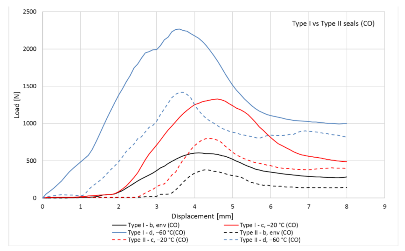
Figure 19 presents the closing force/temperature dependency for Type I and Type II seals. One can observe that the differences between the two types of sealing elements are kept on all the temperature domains, and the results obtained for this type of piston have a large influence over the closing and sealing mechanism final design. For a better overview, the test results (load vs. displacement) for all temperature cases are plotted in
Figure 20.
The obtained results are considerably higher than the ones provided by the theoretical analysis (performed based on sealing elements specifications) and the force which shall be overcome by the mechanical press cannot be ensured only by three compression springs. From this analysis, it was concluded that the maximum pushing force of the piston occurs when the piston starts to enlarge the sealing elements. For decreasing the value of this force, a piston with a new geometrical shape (toroidal shape) was designed and manufactured.
5.2. Piston–Toroidal Shape and Comparison Evaluation of Their Impact over the Mechanism Design
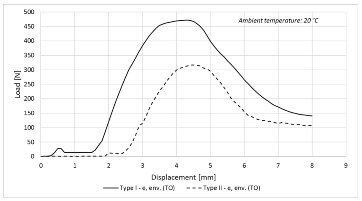
To be able to perform a comparative analysis between the two piston geometries, a test was firstly conducted for the toroidal piston at environmental temperature and the results are presented in
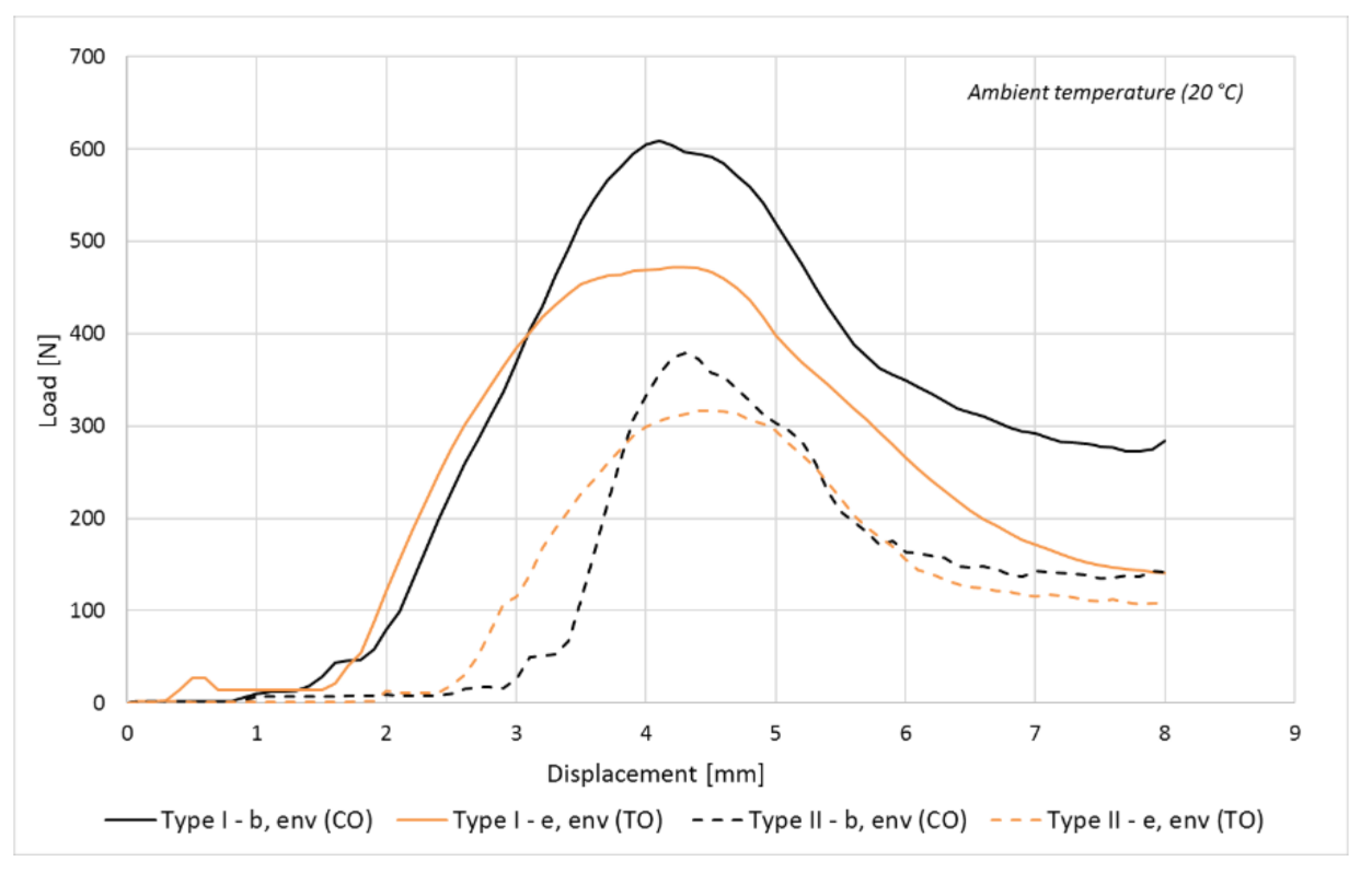
Figure 21. Following the toroidal piston test, a first comparison regarding the necessary force for the closing operation was made using the results obtained for the two pistons (conical and toroidal shape) at ambient temperature and presented in
Figure 22.
The results show that the closing force is lower using the piston with a toroidal shape for both types of sealing elements. Thus, a decision was made to analyse in detail the closing force values for the piston with toroidal shape along with their influence over the design of the sealing and closing system.
For the piston with a toroidal shape (TO), the same testing sequence was followed with regard to the temperature, types of sealing elements and testing procedure.
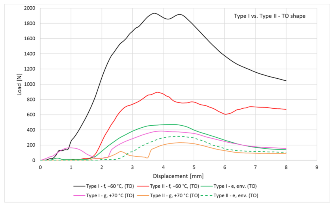
Based on the partial results, it was concluded that the worst-case scenario (the highest values for the closing force) corresponds to the tests performed at −60 °C. Thus, taking into account the temperature influences, several closings and closing force evaluation tests were performed at a temperature of −60 °C, but also at a positive temperature (+70 °C). In
Figure 23 the maximum force/displacement curves are presented for both sealing elements (Type I and Type II), at different operating temperatures and in
Table 4 are summarized the results from the previous tests using the piston with a toroidal shape.
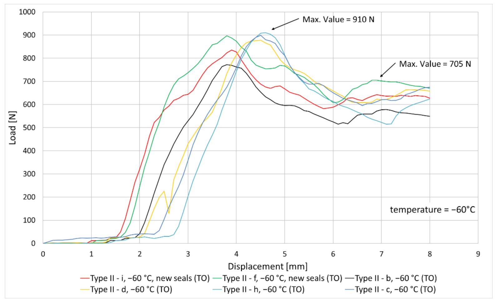
The previous tests performed with the piston having a toroidal shape at −60 °C lead to the decision of increasing the test number for Type II seals to have a better understanding of their behaviour. Maximum obtained forces for each Type II seal test at −60 °C are marked in
Figure 24.
Based on all the tests performed with the piston with toroidal shape, the closing force as a function of temperature dependence is plotted in
Figure 25 for each scenario. It can be observed that the negative temperature has a significant influence over the closing force and that the force value on the cylindrical area remains approximately constant for both types of seals. As in the previous case, the highest values of the closing force for each type of sealing element were considered and interpolated.
Summarizing all the data previously presented, it was determined that the toroidal shape piston along with Type II seals ensure the lowest closing force, leading to the decision of considering these aspects later in the mechanical press design.
5.3. Mechanical Press Motorization
Using the worst-case scenario for Type II seals with toroidal shape for the piston (
Figure 24) and taking into account the ECSS-E-ST-33-01C standard [
19], the next development step consisted in performing the mechanical press motorization. The actuation force necessary to close the vault is supplied by the Mechanical Press which shall be equipped with several helical compression springs defined after the motorization calculus. For the mechanical press motorization calculus, it was considered the worst-case scenario of the closing force operation which is the one performed at minimum operational temperature (−40 °C).
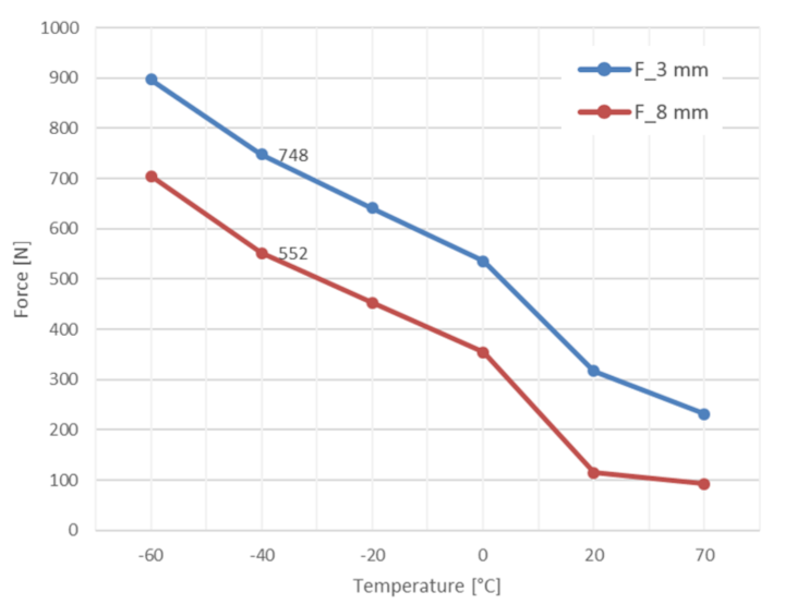
In
Figure 26 the measured values of the closing force are shown and they were obtained following the testing campaign (−60 °C, environmental temperature and +70 °C) for the toroidal shape piston and using Type II seals.
Interpolating the results of the test obtained at −40 °C, two force values were determined, at 3 mm displacement (Fs1 = 748 N), respectively 8 mm displacement (end of the stroke, Fs2 = 552 N). Considering the specifications mentioned in the ECSS-E-ST-33-01C standard [
19] for motorization and actuation factors (sections 4.7.5.3.1e and 4.7.5.3.2e), the minimum actuation forces which shall be ensured by the MP were obtained. The results regarding the minimum actuation forces are summarized in
Table 5.
The driving force applied by the MP springs will linearly decrease from the initial value to a final value at the end of the closing stroke. The driving force values must be above the reference values F1 and F2 set above. Based on the obtained F1 and F2 forces (
Table 5), the helical compression springs of the MP were dimensioned. Considering this, the MP dimensioning was made, respectively how the spring force varies during the 8 mm stroke, which must be ensured by the closing mechanism so that the vault will be in a closed position. The force delivered by the MP during the closing stroke is given in
Figure 27 and it can be observed that the driving force curve is above the reference value set according to the testing campaign results and ECSS standards guideline.
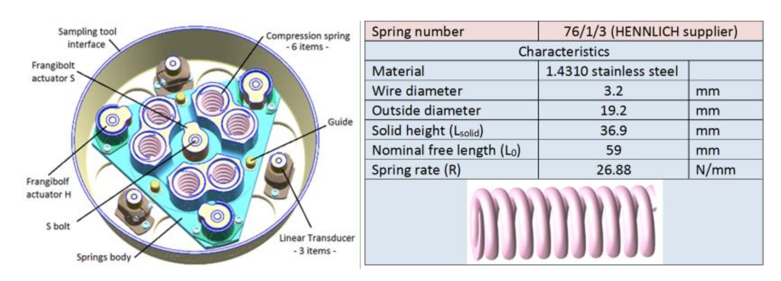
Taking into consideration all this information, the mechanical press was designed and presented in
Figure 28, with 6 compression springs (spring codification 76/1/3, Hennlich supplier) for the following reasons:
The available space for mounting the compression springs is small;
To achieve a uniform distribution of the force on the vault circumference;
The requirement to obtain a high closing force (according to the test results presented above);
The necessity to ensure an 8 mm stroke to perform the vault closing operation.
6. Conclusions
During the testing campaign, two types of sealing elements and two shapes of the sealing surfaces for the Sample Container were investigated to obtain smaller forces during the closing operation. The seals with a U-shaped spring and jacket made of Fluoroloy A28 (Type II seal) require a smaller force than the other one (Type I seal). It was concluded that the toroidal shape piston needs a smaller force to enlarge the jacket and spring of the sealing elements.
The sealing elements are composed of a plastic jacket and a metallic spring. The flexibility of the jacket material is temperature-dependent, stiffer at lower temperatures and softer at higher temperatures. Due to this behaviour, the testing campaign was performed considering different temperatures (environmental temperature (20 °C), −20 °C, −60 °C and +70 °C) which confirmed that the closing force is temperature-dependent too. Using the results from the testing campaign, especially the ones at −60 °C, which represent the worst-case scenario, the maximum closing force which shall be ensured by the mechanical press was identified. The testing campaign is vailable at the
Supplementary Materials.
The obtained results from the testing campaign were used as input for the mechanical press motorization, which consists in dimensioning the helical compression springs foreseen to deliver the closing force. More exactly, based on these tests and calculations, the necessary spring rate to develop a sufficiently large force to ensure the vault closing was established. During the testing campaign of the closing and sealing system, the mechanical press design was validated through functional closing tests.
As each Space Agency (i.e., ESA, NASA, JAXA) is focused on exploring planet Mars or Martian Moons and collecting regolith samples from Mars natural satellites in future missions, the work carried out in the design, manufacturing and testing a sealing and closing mechanism for a Phobos Sample Return Mission was highly appreciated by ESA. This represents a high possibility that the system architecture designed by COMOTI to be used in future scheduled missions. It should also be highlighted that the possibility of the mechanism to be scaled up and used in Sample Return Missions will need a higher closing force or be able to cope with higher robotic arm misalignments.


 ,
, 


