1. Introduction
In the development of innovative reactor systems, zero or very low power experiments have historically been seen as the first step in the development of a new reactor program or a new technology [
1]. Already, the planning as well as the construction creates a multitude of learning opportunities which will extend into the operation and the experimental program [
2]. In [
3], and in the first part of this publication series [
4], the importance of a zero-power reactor experiment for the process of developing a new, innovative reactor concept such as a molten salt fast reactor was worked out, and the challenges, due to the homogeneous core composition (unity of the coolant and fuel) of a molten salt reactor, were described. In this publication, two major parts required for the safety approach of a research reactor [
5], the potential control and shutdown systems, are investigated. The relevance of the topic of instrumentation and control was worked out by IAEA in their Safety Standards Series [
6]. In the third part, the role of the reflector was discussed and analyzed [
7]. A zero-power reactor experiment for a molten salt reactor is significantly different to the existing heterogeneous experiments based on pins with the requirement to understand the effects of heterogeneity. On the one hand, the homogeneous nature of the reactor media will require novel approaches for the design, operation, and control. On the other hand, the experimental setup must be designed, developed, and invented. To avoid a disturbance of the homogeneous system is a significant, new challenge for designing an innovative approach for the control and shutdown of a homogeneous reactor experiment. The focus of the development is to deliver a control and shutdown system which avoids a major disturbance of the homogeneous arrangement as it would occur in the case of the use of control rods in industrially operated light-water reactors.
Most of the currently operated reactors rely on different approaches for the control and shutdown, while very often, the control system can act as an independent, diverse shutdown system. A typical example is the use of control and shutdown rods in pressurized reactors which is complemented with a boric acid operated control system for burnup compensation. In boiling water reactors, the control and shutdown system is based on control blades, which are complemented with operational control through the recirculation pump speed and the related void content in the core and a diverse shutdown system based on boric acid injection. In both reactor types, burnable poisons are widely used to reduce the excess reactivity of fresh fuel assemblies.
CANDU reactors have a more sophisticated control system which is required due to the large core size. The control system consists of moving adjuster rods and varying the water level in vertical cylinders [
8] mainly for the control of the flux shape, while burnup compensation is only required to a very small extent due to the online refueling. “The first shutdown system is made up of rods that drop automatically and stop the chain reaction if something irregular is detected. The second system injects a liquid, or poison, inside the reactor to immediately stop the chain reaction” [
8]. Technically, the option of draining the heavy-water moderator for shutdown would be another option which has been discussed.
Sodium-cooled fast reactors are typically controlled via different sets of rod systems, safety (shutdown) rods, regulating rods, rapid shutdown rods, and sometimes additional shutdown rods [
9] with different types of drives, and even flexible chains have been investigated in some projects. The sodium-cooled fast reactor community has also been working on passively activated safety shutdown systems [
10].
The German pebble bed HTGR used 36 absorber rods for power control and reactor scram, which are inserted or dropped into the side reflector via gravity, and for long-term shutdown, 42 absorber rods with pneumatic drives could be inserted directly into the pebble bed [
11]. However, other approaches such as withdrawing a certain amount of pebbles from the pebble bed reactor have been investigated after problems occurred with the insertion of the shutdown rods into the pebble bed. The use of a zero-power reactor system, KAHTER [
12], developed for the design of the industrial demonstrator THTR created the potential to investigate, on the one hand, the design of the industrial demonstrator through experiments to support the future system understanding. On the other hand, a zero-power facility allows understanding and testing new approaches, such as the effect of withdrawing pebbles in this case, which will help in the system optimization.
For future molten salt reactors, control rods [
13] and core drainage are proposed for shutdown for MSR systems and have been used in MSRE [
14]. Initial studies indicate that burnup control could be achieved through control of the core temperature, due to the strong thermal feedback effect [
15] which allows compensating a significant amount of reactivity with only a moderate change in the salt temperature. The approach of draining the salt will not work in an MSFR zero-power experiment, which will most probably take place in the first step in a solid arrangement in order to reduce the complexity.
Looking into more exotic approaches in control systems, tests have been performed on “Critical-Assembly Experiments on a Reflector Control System for a Boiling Reactor” [
16], reflector manipulations have already been used very early on in reactor physics experiments [
17], and reflector manipulation drums are often proposed in very compact space reactors [
18] or training, teaching, or research reactors [
19,
20]. For critical experiments, moderator-level manipulation has been used for criticality determination [
21], and changing or manipulating the reflector conditions is also used in critical assemblies [
17]. Splitting of the spherical core into two half spheres is another approach for shutdown which has been used in some very small educational reactors. In the most recent zero-power experiments for accelerator-driven systems, YALINA [
22] and GUINEVERE [
23], the control and shutdown function was provided through accelerator beam control.
Based on this literature overview on control and shutdown mechanisms, the work we provide here will aim to develop and evaluate diverse control and shutdown approaches as well as their interplay on the control and shutdown of a homogeneous critical zero-power experiment for a potential molten salt fast reactor through the use of a multitude of modeling and simulation results using different tools of the SCALE package.
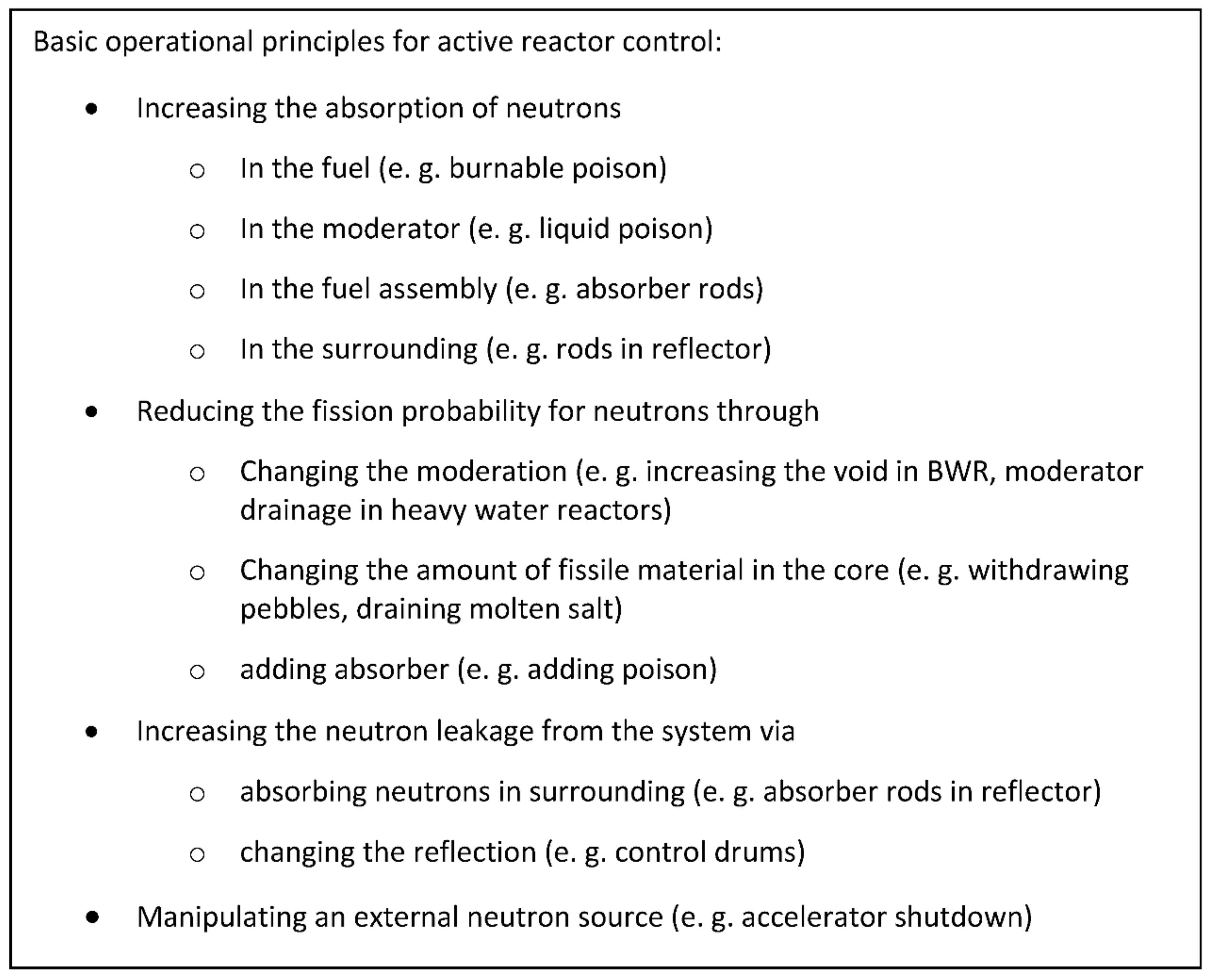
2. Basic Considerations for Control and Shutdown
Typically, a reactor is controlled through a set of active control systems based on the basic principles of reactor control (see
Figure 1) and system-inherent physical processes.
These active principles are supported in almost every well-designed reactor system by inherent control mechanisms based on the feedback effects due to temperature changes and the resulting effects (e.g., fuel temperature effect, moderator temperature effect, coolant density effect), even if these effects are not always all negative, and the overall balance of all feedback effects must be negative to ensure stable reactor operation.
From the basic list above, it is already apparent that some control and shutdown approaches can act in parallel on different principles, e.g., control rods in the absorber to reduce the number of neutrons and change, through this, the neutron leakage from the core. Interestingly, the described inherent control mechanisms of reactors act on the same underlying basic principles, e.g., the increase in the fuel temperature leads to an increase in the resonance absorption of neutrons, or the moderator density effect affects the fission probability of the neutrons due to a change in their energy.
To understand the specific demand for the control and shutdown system to be designed, it is important to understand the specific boundary conditions. Two major points have to be mentioned here: Molten salt fast reactors typically consist of a homogeneous core configuration in contrast to typical solid fueled reactors with a heterogeneous fuel assembly and core composition. A zero-power experiment will have the opportunity/requirement to operate under room temperature with a solid salt, as well as a molten salt system at a higher temperature. Thus, the control system should be able to cope with both conditions, leading to a system with weak feedback effects at the solid state and the potential for a much stronger feedback in the molten state. In addition, in a reactor physics experiment, the control system has an additional function, where the system is typically used for the exact determination of criticality which has a strong role in the validation of codes on criticality, e.g., via the determination of the control rod position in both the experiment and the calculation.
The described demand specifies the following requirements:
The shutdown and control system should be diverse;
The systems should be able to operate independently;
Both systems should allow a safe shutdown;
The control system should not create a major inhomogeneity to avoid any impact on the experimental investigation;
The control system should deliver sufficient sensitivity for the validation of criticality, e.g., measurable and reproducible movement following a temperature change in the core;
The interaction of the systems should not impinge on their individual purpose;
Both systems should be applicable in a solid as well as in a liquid core.
Based on these requirements, two different systems are proposed:
Shutdown via splitting the reflector, or a part of the core with the reflector, from the main part of the core downwards. This can provide a fail-safe solution for the ultimate shutdown driven by gravity.
Control via a vertically movable radial reflector as a movable sleeve around the reactor.
Both systems will be usable for a zero-power system with a liquid as well as a solid core, and even more importantly, both systems should somehow work at the integral system level without disturbing the central part of the core, which will be the essential area for the experimental measurements. Both approaches should also be able to act as a singular system, as well as together. Their interaction and the sensitivity of the control system will be investigated in the following through the use of a multitude of modeling and simulation results using deterministic and Monte Carlo tools of the SCALE package.
3. Codes and General Modeling
The salt system is based on density versus temperature curve data from a Russian study [
24] (see
Table 1). The data are used for the analysis based on a reference temperature of 980 K, with changes of ±50 K, for the analysis of feedback effects. The data should be seen as a starting point for initial studies with the limits already discussed in [
7].
Based on the coefficients presented in
Table 1, the temperature-dependent density is calculated using the following formula:
Based on the given salt system investigation [
15] and the first investigations on the required dimensions for a zero-power experiment [
4], the heavy metal-rich case with 20%NaCl-56.35%UCl
4-23.65%UCl
3 was used for the following investigations of control and shutdown options.
The main part of the simulations for this initial study of zero-power reactor control and shutdown approaches was performed using the KENO-VI, a Monte Carlo solver module of the SCALE code system [
25], to analyze the 3D system. “KENO-VI uses the SCALE Generalized Geometry Package, which provides a quadratic-based geometry system with much greater flexibility in problem modelling but with slower runtimes. Both versions of the KENO perform eigenvalue calculations for neutron transport primarily to calculate multiplication factors (k
eff) and flux distributions of fissile systems in both continuous energy (CE) and multi-group (MG) modes. They are typically accessed through the integrated SCALE sequences. KENO’s grid geometry capability extends region-based features for accumulating data for source or biasing parameter specifications, as well as for tallying results from a calculation for the visualization or communication of data into or out of a calculation” [
26]. The serial studies on enrichment variation and the analysis of the effect of the removal of the reflector are based on another code of the SCALE package, POLARIS [
27], which normally provides a 2D lattice physics analysis capability that uses a multi-group self-shielding method called the embedded self-shielding method (ESSM) and a transport solver based on the method of characteristics (MoC). This code has been compared to different Monte Carlo solvers [
28], besides the validation performed by the developer, Oak Ridge National Laboratory. The analysis was extended for creating a deeper understanding of the neutron spectrum by using the multi-group deterministic S
n transport calculation sequence TRITION/NEWT.
The multi-group KENO-VI analysis is based on the v7-252 cross-section set (based on ENDF/B 7.1) of the SCALE package [
25], which is also the basis for the TRITON/NEWT as well as the POLARIS calculations, while the continuous energy version of KENO-IV uses the ce_v7.1_endf library of the SCALE package.
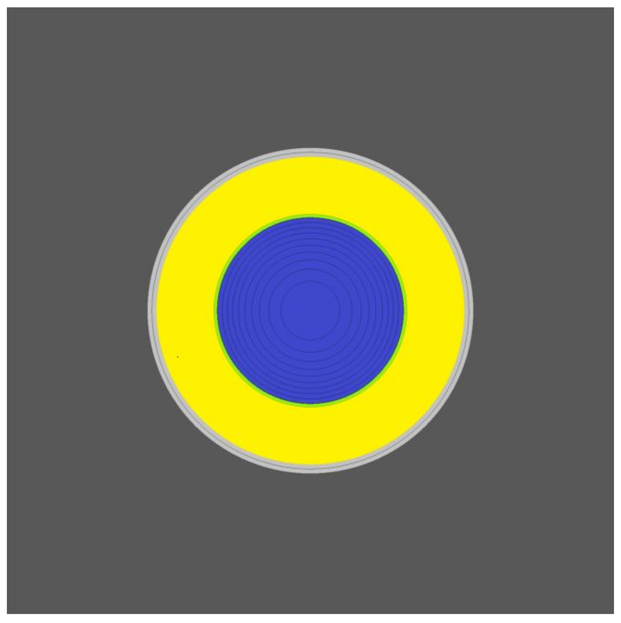
For this study, a general 3D KENO-VI model was built (see
Figure 2), representing a cylindrical core surrounded by a thin vessel and a reflector on all surfaces, which will be successively modified in dimension and organization for the simulation of the proposed control and shutdown approaches. For completeness, the used POLARIS model is presented in
Figure 3, and the used NEWT model for the neutron spectrum analysis in
Figure 4 has already been used in the previous study [
4].
For all Monte Carlo simulations, a setting of 2000 generations with 20,000 particles was used, and the source convergence was checked. This setting leads to an accuracy of ±30 pcm and below at 95% confidence, which is more than sufficient for the current level of the investigation of the control and shutdown systems as well as their interplay.
4. Modelling & Simulation Results
4.1. Shutdown System Study
The currently proposed configuration for a molten salt fast reactor experiment is based on a homogeneous core composition with a heavy metal-rich salt composition containing 20%NaCl-56.35%UCl
4-23.65%UCl
3 as it has been investigated for the breeding [
28] and feedback [
15] studies for iMAGINE.
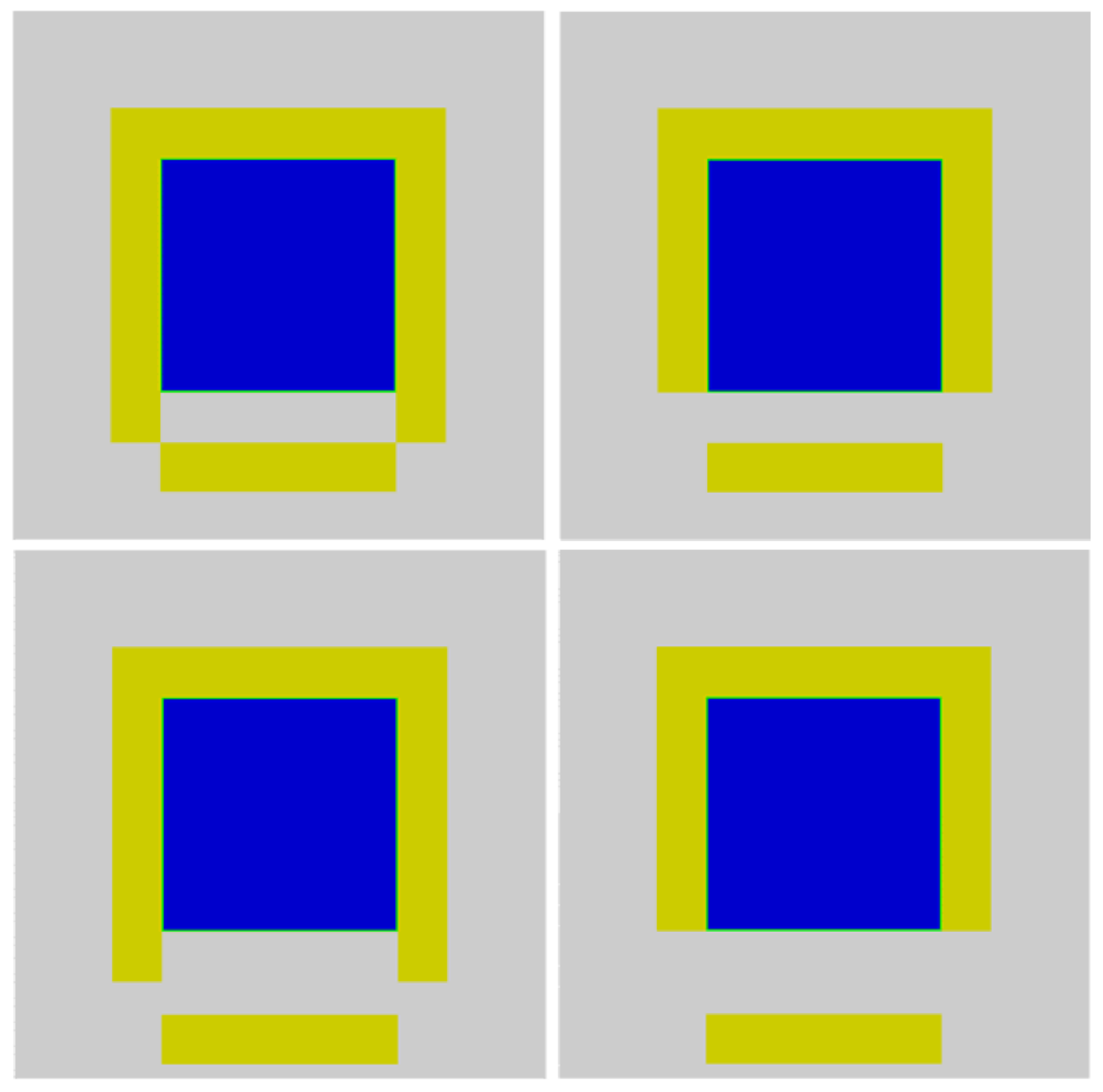
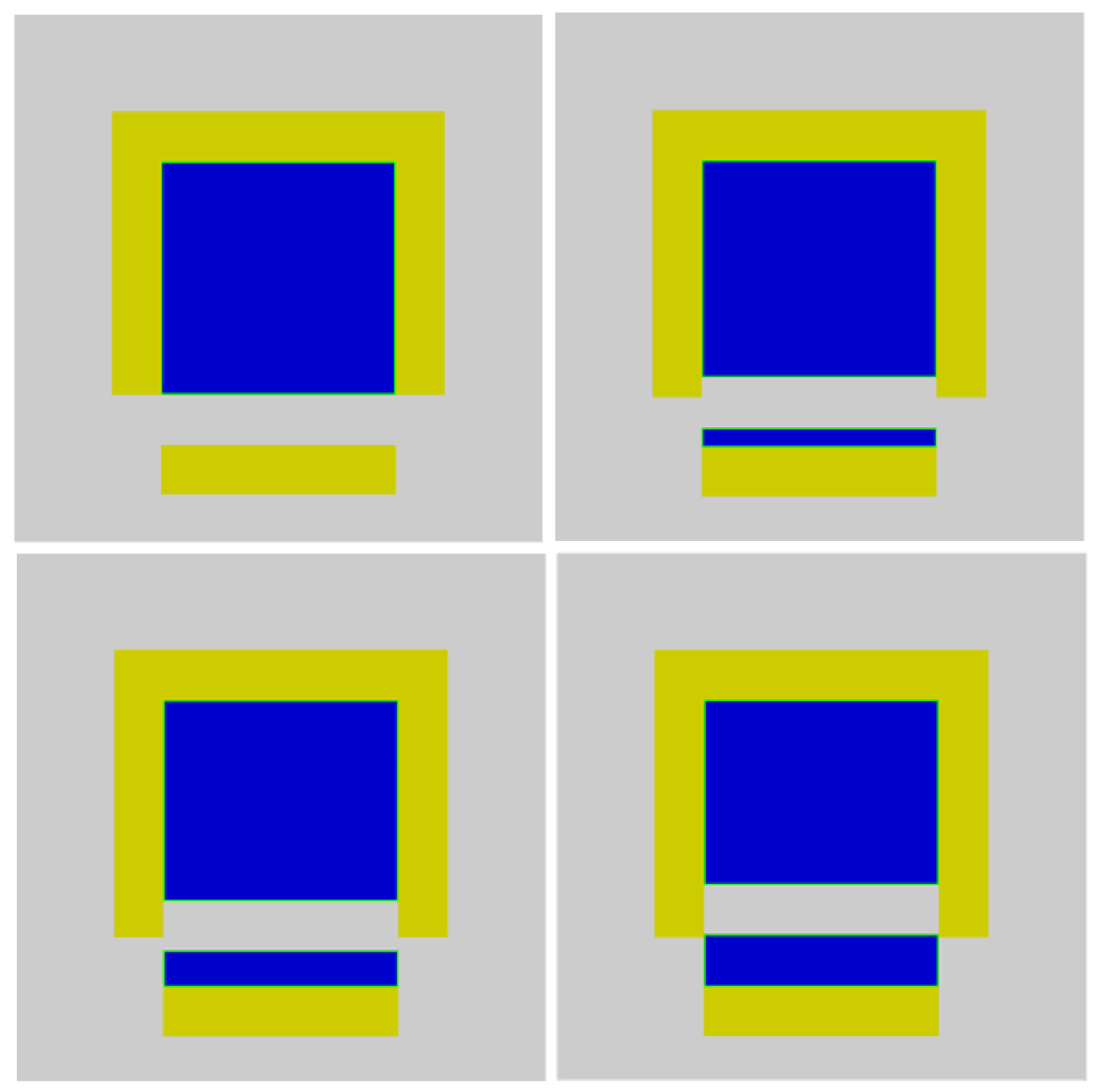
Such a homogenous system is in strong contrast to the classical zero-power reactor studies which are, in most cases, designed to investigate heterogeneous configurations, having the aim of understanding the effect of the heterogeneity. In a homogeneous system, the investigation of the undisturbed system will be of high interest, and thus a shutdown system which introduces a perturbation in the homogeneous structure would be a penalty. Looking into the study of homogeneous critical systems, these systems are often controlled via neutron leakage. In addition, the system should ideally be applicable in the solid state at room temperature for a first operational stage as well as for the liquid core in a higher temperature operation at a later stage of the experiments. A first guess of such a shutdown system is presented in
Figure 5. In this approach, the bottom reflector of the core will be removed. Two different approaches are investigated: in case 1, only the bottom reflector is removed, while the side reflector is not changed, and thus only a gap is created, while in case 2, the side reflector will be limited to the bottom of the core, and thus a streaming path for neutrons to leave the system will be opened. Case 3 replicates case 1 but with an opening of 50 cm compared to the 30 cm opening in case 1. Case 4 follows the same principle, where it replicates case 2 but with a 50 cm opening instead of 30 cm. All 4 cases were calculated based on identical Monte Carlo settings and delivered the following outcome for the shutdown margin: case 1, −1855 ± 33 pcm; case 2, −2737 ± 33 pcm; case 3, −2596 ± 30 pcm; and case 4, −3181 ± 33 pcm, all with a 95% confidence interval, which indicates that the statistics of the Monte Carlo calculation do not have a significant influence. The change from case 1 to case 2 aims to limit the influence of the side reflector and increase the shutdown margin by almost 50%. Increasing the opening from 30 to 50 cm increases the shutdown margin by ~40% when the side reflector is not reduced, but only by a bit more than 15% when the side reflector is cut. Thus, creating a wider opening is only of interest when it creates an additional streaming path for neutrons, as in case 3. However, all cases demonstrate that the achievable shutdown margin is only in the area of 2000 to 3000 pcm, which is perhaps insufficient.
Based on the above achieved results, it would be of interest to enhance the effect of the removal of the bottom reflector. A promising approach could be to remove not only the reflector but also a limited layer of the core. A comparable strategy was implemented in the teaching reactor SUR-100, which is based on a structure of polyethylene plates with homogeneously distributed fuel. However, while the SUR-100 is only a very small core with a very limited mass, the system for a zero-power reactor will have a substantial mass. Thus, specific solutions have to be developed to deal with this challenge. The investigation of this strategy is presented in the models created for the analysis and shown in
Figure 6. For illustration, the base case is shown in the left top corner, and it is identical to case 2 of
Figure 5. In the following steps, slices of 10 cm (top right), 20 cm (bottom left), and 30 cm (bottom right) were moved with the reflector away from the core. This exercise was performed for all 4 cases defined in
Figure 5.
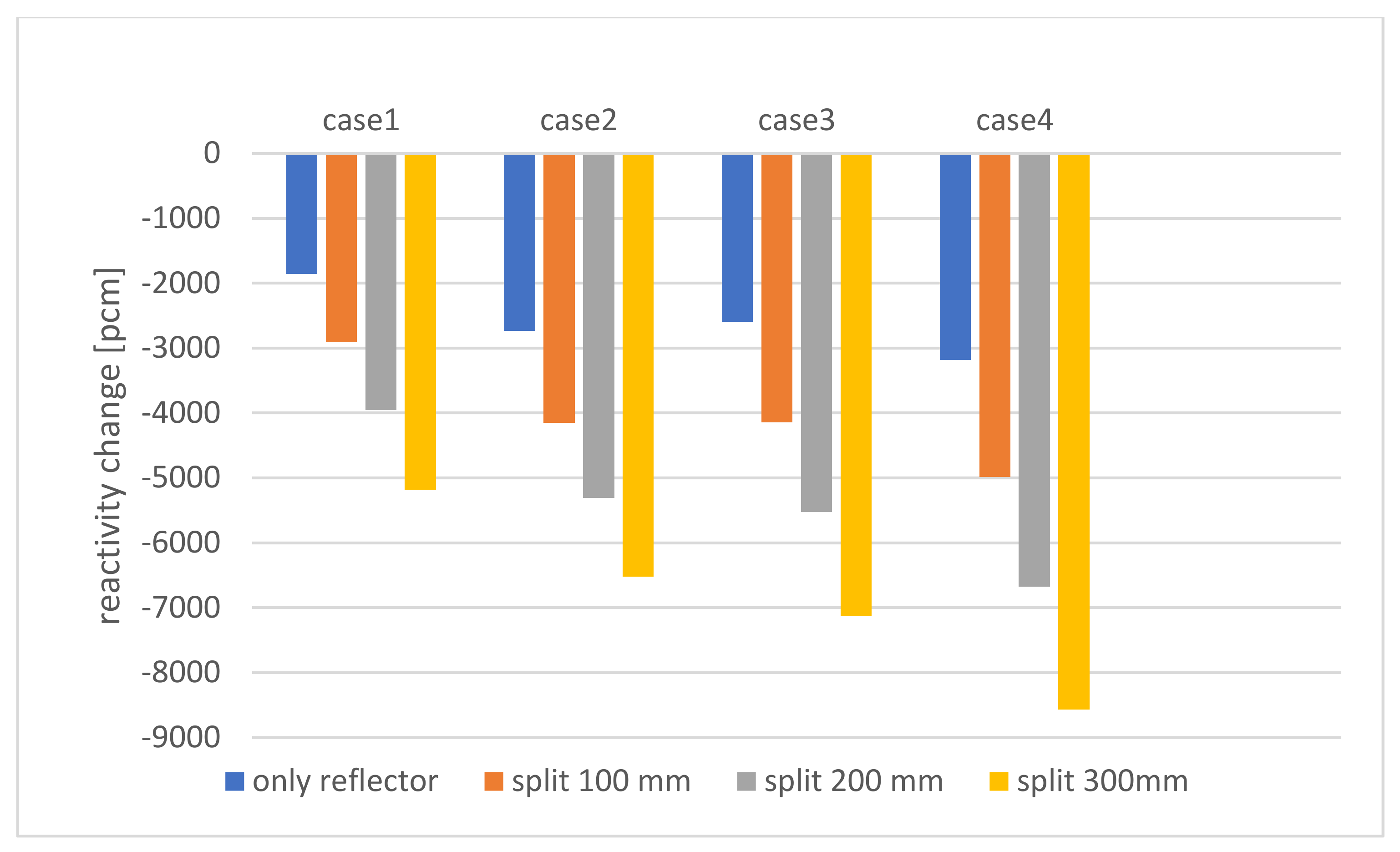
An overview on the combined result for all cases is shown in
Figure 7 for the 30 cm opening for all cases. The general tendency is for all 4 cases to be comparable. The 10 cm slice increases the shutdown margin by ~50%, the 20 cm slice by ~100%, and the 30 cm slice by slightly more than 150%. The gain, in the form of the shutdown margin, is slightly weaker in case 2, where the reference case (case 1 in
Figure 5) has the strongest shutdown margin. Considering all the results shown, it is apparent that the removal of the bottom reflector has the potential to be used as a shutdown system, and the negative reactivity margin can be tailored to the demanded shutdown reactivity, which will have to be discussed and agreed on with the regulator at a more detailed design level.
From a more technological view, the thickness of the layer to be moved should be as thin as possible. On the one hand, the whole design of the control system and the related moving parts will be more challenging with the increasing weight of the piece to be moved, which creates the demand for an as thin as possible layer. On the other hand, the core part to be moved will limit the opportunity for the insertion of the instrumentation, and the thicker the layer is, the less undisturbed core volume will be left at the top, which will be used for the investigation of the behavior of the homogeneous system. Thus, finally, the dimension of the layer used for the shutdown system will be a typical optimization problem to create a sufficient shutdown reactivity while limiting the disturbance on the experimental performance.
4.2. Control System Study
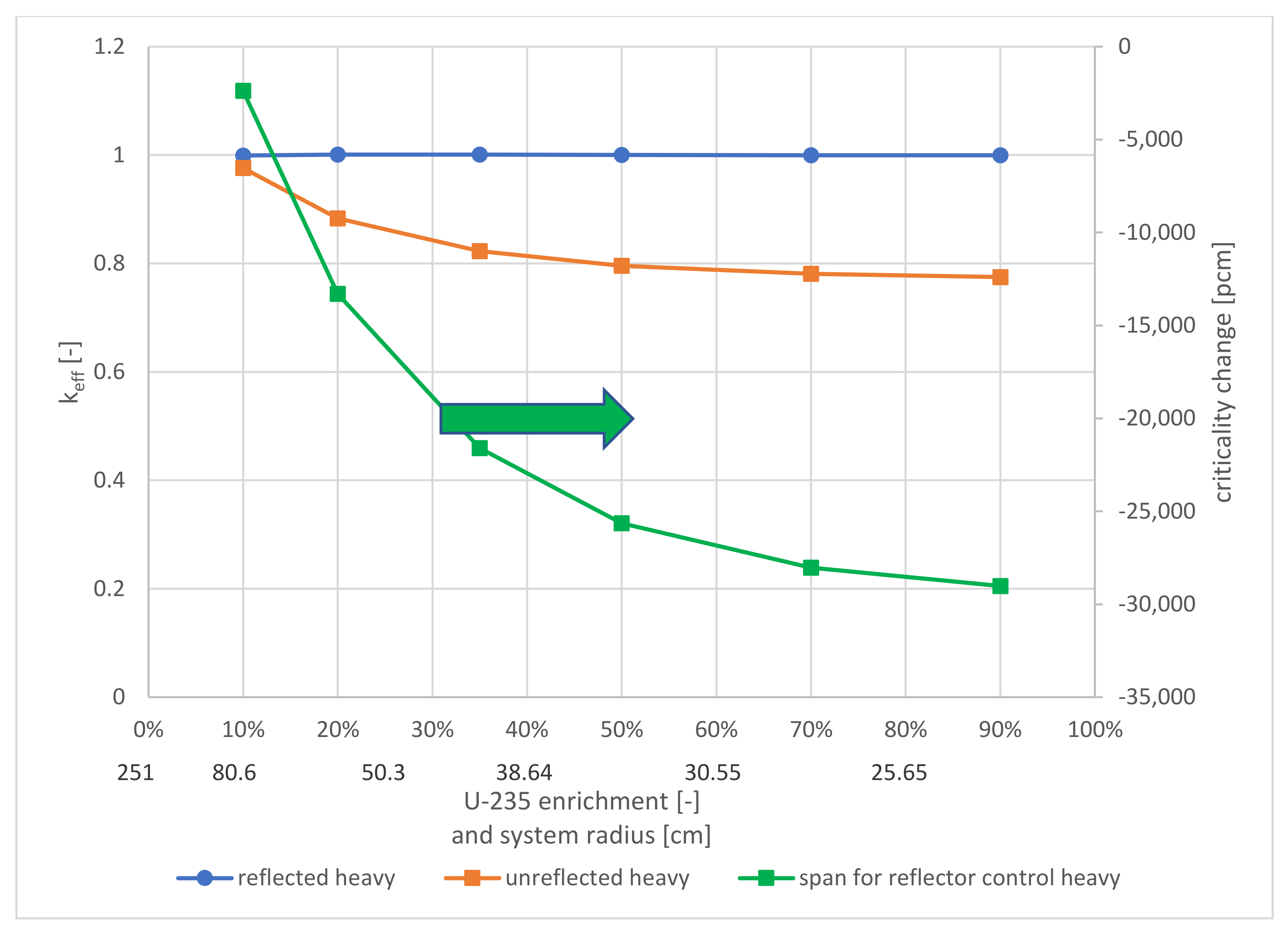
The boundary conditions of ideally not disturbing the homogeneous arrangement of the core described for the shutdown system are even more important for the control system which will be used to start up the reactor and to keep the reactor in the critical state. The additional request on the applicability for the solid as well as the hot liquid state is also essential for the control system. Based on these requirements, the control of the criticality via the movement of the radial reflector seems to be a promising option, especially if the system would be efficient enough to assure that most of the core can stay reflected to obtain good opportunities for the evaluation of the reflected configuration. However, this way of control could, in addition, allow the investigation of the neutron flux distribution in the unreflected core (the reflector space in the model is filled with a vacuum), too. The potential core criticality change, investigated in the 2D system, is presented in
Figure 8 as a function of the fuel enrichment. From this evaluation of the criticality change, the limitation of the radial reflector control is obvious. The system using the reflector for control will strongly increase in efficiency with decreasing reactor core size. The reactor size coincides in the investigated system with the uranium enrichment, while the effect of the salt configuration, and thus the amount of the NaCl carrier salt, is only very minor. The figure indicates that a sufficient criticality change by removing the radial reflector can only be achieved for systems with at least 20% enrichment and thus an estimated 2D system radius of about 80 cm. For the chosen system with a 35% enrichment, the expected value of this initial investigation will be in the range of more than 20,000 pcm. Thus, a broad range of configurations and even a significant temperature range with the resulting reactivity change due to the strong feedback effects [
4] can be evaluated and/or compensated with the proposed radial control reflector holding the reactor in a critical status.
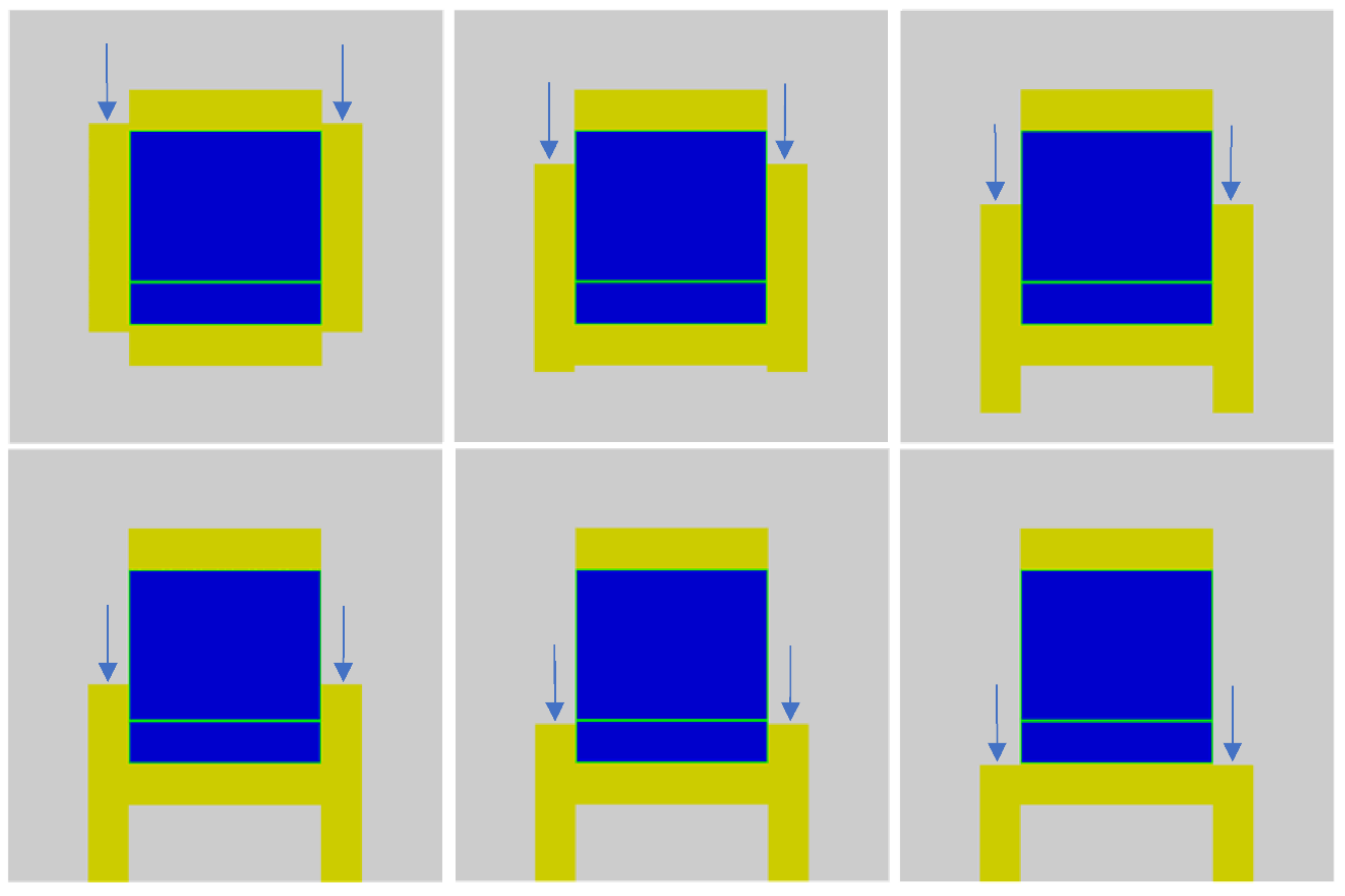
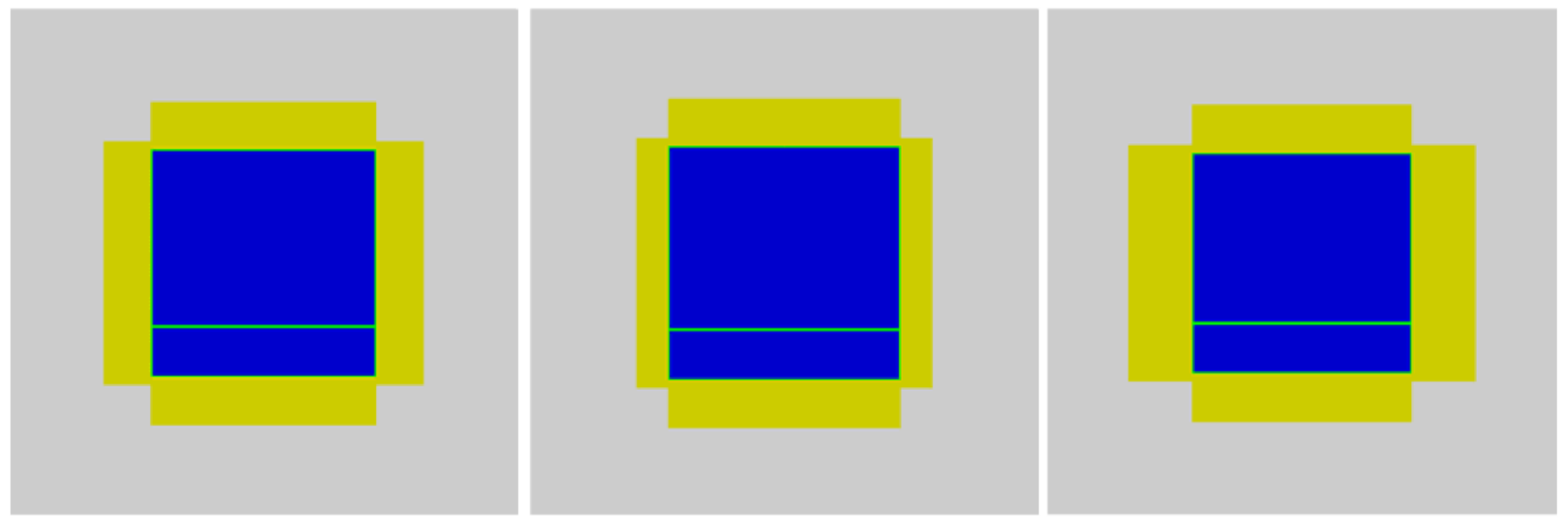
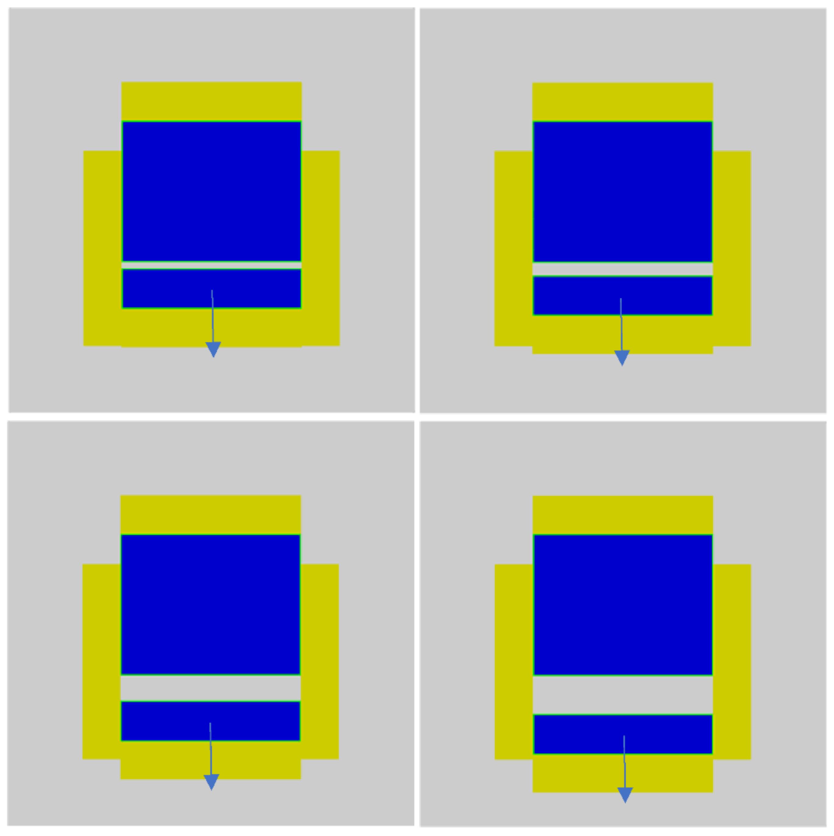
Based on this initial 2D evaluation, the approach of a control system using a vertically moving radial reflector will be investigated in more detail in a 3D analysis using KENO-VI. The first step for the 3D analysis is to determine the appropriate “slightly over critical” configuration—a cylinder with a diameter of 140 cm and a core height of 140 cm delivers a k
eff of 1.02033 in the KENO-VI multi-group calculation. The used core model is presented in the left upper corner of
Figure 9, using a 10 mm-thick stainless-steel wall and a 30 cm layer to split off for the shutdown system. The following images from left to right in the upper and then the lower row visualize the concept of the radial reflector control accomplished by moving the radial reflector downwards in a stepwise manner. The visualized pictures are only a few of the used steps investigated for the analysis of the control effect curve of the control system. The radial reflector in the undisturbed reference system reaches 6 cm further than the core at the top and the bottom to assure that the effect of moving the reflector on the core criticality starts already after a limited amount of movement.
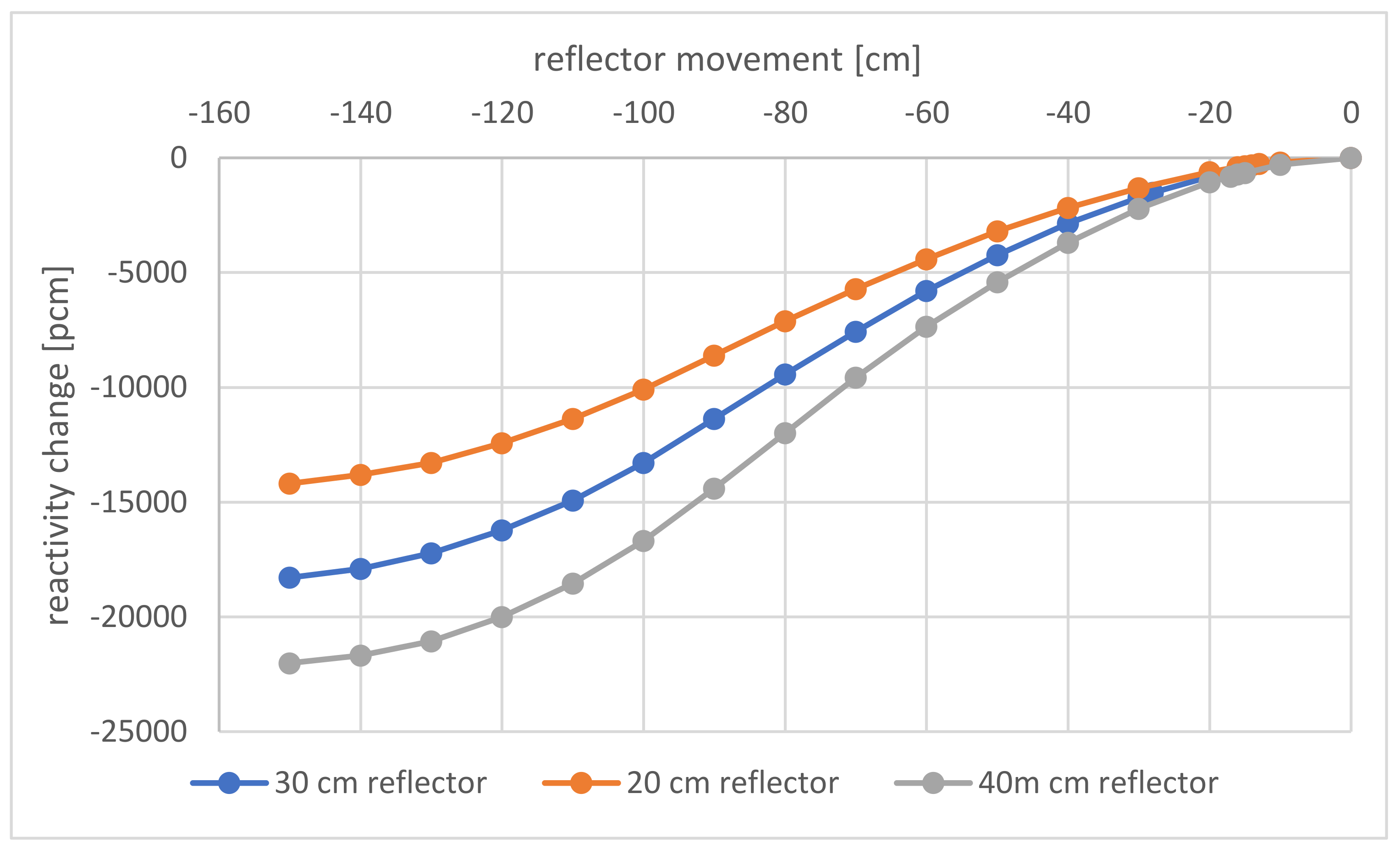
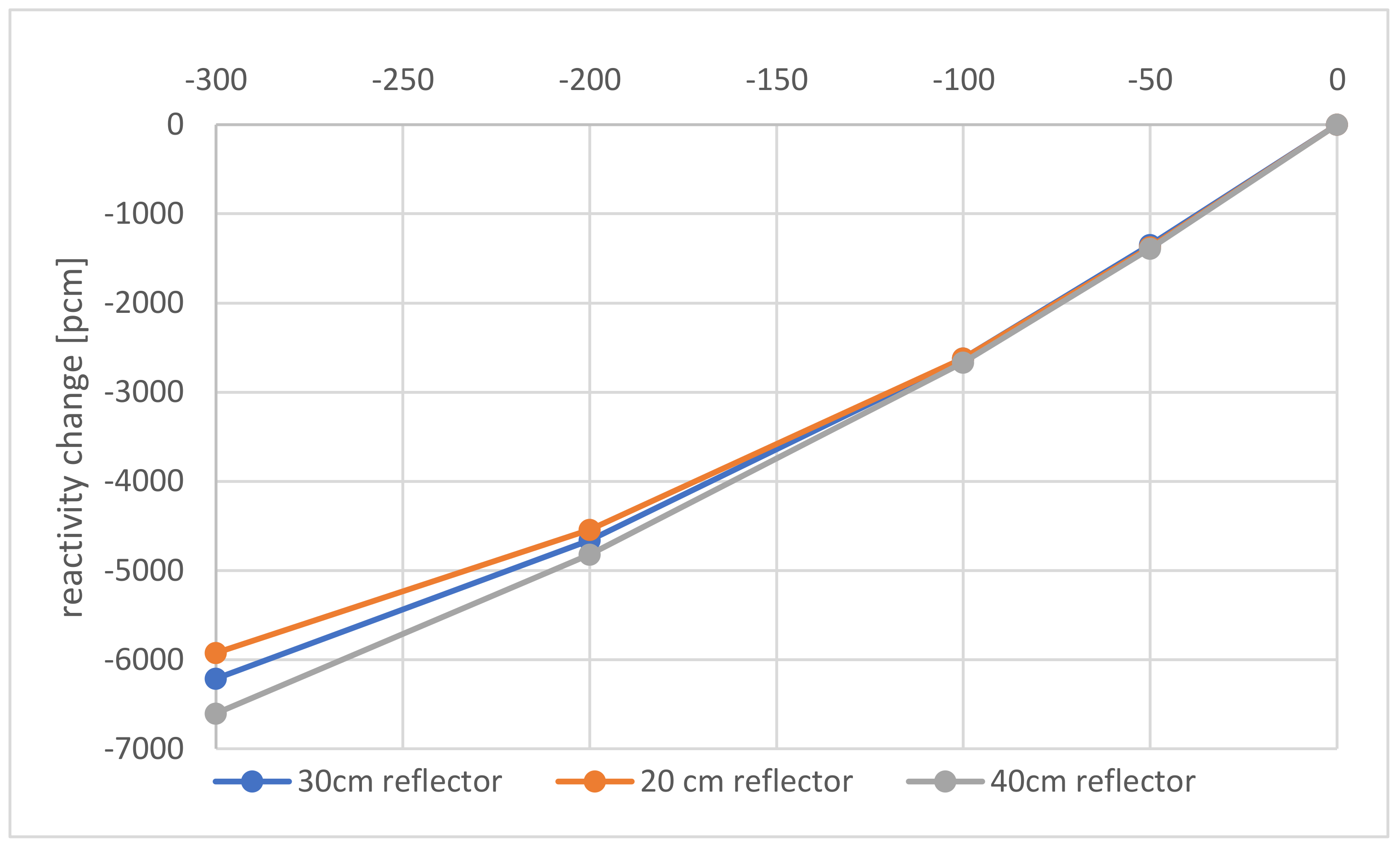
The analysis of the control reactivity curve is accompanied by the analysis of the effect of the thickness of the reflector by investigating not only the reference case with the 30 cm-thick reflector but also a case with a reflector reduced to 20 cm and one with an increased reflector thickness of 40 cm (see
Figure 10). The 20 cm reflector case requires a core with a 144 cm diameter and a height to assure a critical reactor with some reserve criticality margin, while the increase in the thickness of the radial reflector to 40 cm allows reducing the core size to 136 cm in diameter and height. The axial reflector is maintained with a thickness of 30 cm in each of the cases.
The control curves shown in
Figure 11 indicate a reactivity control span of ~12,000 pcm for the 20 cm-thick reflector, ~16,000 pcm for the 30 cm-thick reflector, and ~20,000 pcm for the 40 cm-thick reflector. The curves were determined through Monte Carlo calculations with the reflector moved downwards in 10 cm steps from the original starting position until the lower end of the core was reached. All curves show the characteristic trend with a lower efficiency of the control system at the beginning and at the end of the movement path. This means the control system allows a very sensitive control at the beginning and at the end since moving one increment has a smaller influence on the overall core criticality than when the control system is acting somewhere around the core center where the neutrons typically have a higher importance. Thus, the increase in the leakage has a stronger influence on the criticality in this area. The control response to the thickness of the reflector is almost proportional to the thickness of the reflector, even for the 40 cm-thick reflector. This indicates that there would still be an opportunity to increase the reactivity change if required, since only a very small saturation effect can be observed. In general, the criticality change, which is effected by the control system, is very wide in all investigated cases, which will allow compensating for the large reactivity changes which are expected for molten salt systems due to the very strong feedback effects caused by the strong effect of the density change in the salt which is acting as a coolant as well as a carrier for the dissolved fuel [
28].
Finally, the decision on the thickness of the reflector and the use of the reflector for controlling the system criticality will follow different objectives since the control system design will be dependent on the weight of the component which has to be moved and the ideal system should be lightweight, which points to a thin reflector. However, from a core design, control, and cost point of view, the objective is an as efficient as possible reflector, since, as shown above, the thickness of the reflector has an influence on the core size and thus on the amount of fuel required for the experiment, which is one of the costliest parts of a zero-power experiment. The results for the criticality study show the influence of the reflector thickness on the required volume, where the reference case with the 30 cm-thick reflector leads to a volume of ~2.15 m3, the case with the 20 cm-thick reflector requires ~2.35 m3 (+9% core volume), and the case with the 40 cm-thick reflector requires only 1.98 m3 (−8% core volume).
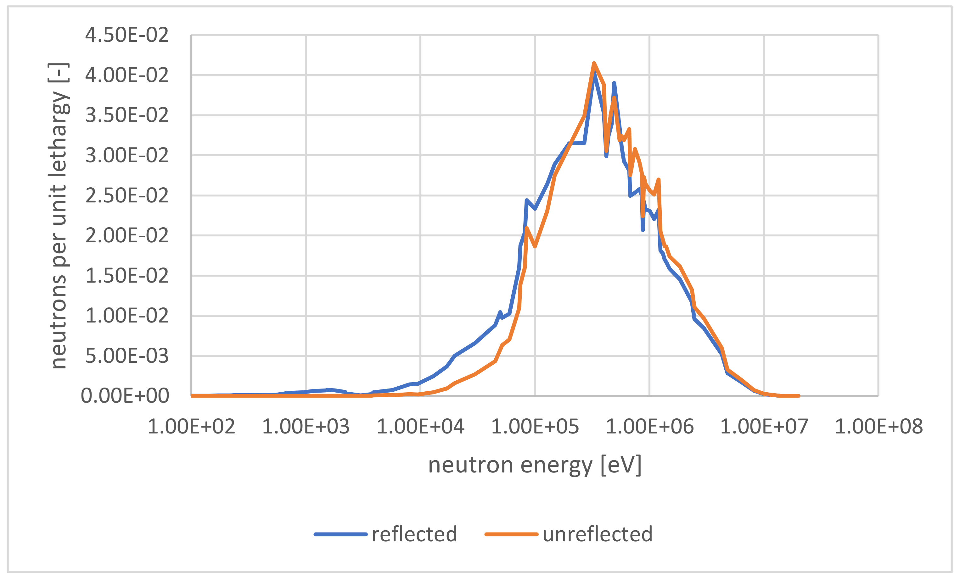
Moving the reflector for the control of the reactor will have some strong influence on the neutron spectrum since the core leakage will significantly change. The analysis of the neutron spectrum based on a 2D calculation using the deterministic TRITON/NEWT sequence of the SCALE package is presented in
Figure 12. The general neutron spectrum is typical for a fast reactor with the majority of the neutrons between 10 keV and 2 MeV, with almost no thermal neutrons appearing in the system. The two different neutron spectra were both calculated independently and could be interpreted as the neutron spectrum in the upper core part: unreflected in the case the reflector is moved downwards, and the neutron spectrum in the lower core part: reflected since, there, the reflector will still enwrap the core. Both of the neutron spectra shown can be seen as the two extrema since they are calculated for an axially infinite system. Thus, in the region where the top end of the reflector is located, some mix of both spectra will appear. The spectrum for the unreflected case is somewhat harder than for the reflected case where some lower-energy neutrons are reflected back into the core after they have lost energy in the reflector. The appearance of neutrons with energies around 1 keV was indicated in [
4] as neutrons which almost solely exist in the reflector where no fission events take place. As soon as these neutrons penetrate back into the core, they will be absorbed and have a high probability of creating fission reactions. Thus, the fission density in the outer core area will be slightly higher in the reflected core part. When the instrumentation for the zero-power core is designed well, this change will hopefully be recognizable. Thus, a neutron flux distribution can be measured for the reflected and the unreflected core to identify the effect of the reflector on future reactor operation where the reflector will be a design feature to improve the neutron economy in the core, even if it is expected that the effect of the reflector will be lower with increasing core size, as it is already visible in
Figure 8.
Following the separate study of a potential reactor shutdown system and a reactor control system, the next chapter will deliver the analysis of the interplay between both systems which will be relevant for the operation. It is apparent that there will be a noticeable interplay between the systems when analyzing the results presented in
Figure 7, where the effect of the presence or absence of the side reflector has a strong influence on the shutdown reactivity.
4.3. Control and Shutdown System Interaction
The basic approach for this study will be taken by initiating the shutdown from the critical state of the three cases with varying reflector thicknesses at the appropriate reflector position. The configuration of the critical state core with a 30 cm-thick reflector, with the reflector positioned at −29 cm from the original position, leads to a k
eff of 1.0003, and different openings of the shutdown system are presented in
Figure 13. From the stepwise figures, it is clear that the combination of the control and the shutdown system always tends to lead to a configuration such as that found in cases 1 and 3 in
Figure 5, with the streaming path for the neutrons to the side mostly or completely blocked by the side reflector.
The efficiency of the shutdown system will be evaluated regarding the different openings of the shutdown system as well as regarding the influence of the thickness of the side reflector on the shutdown reactivity.
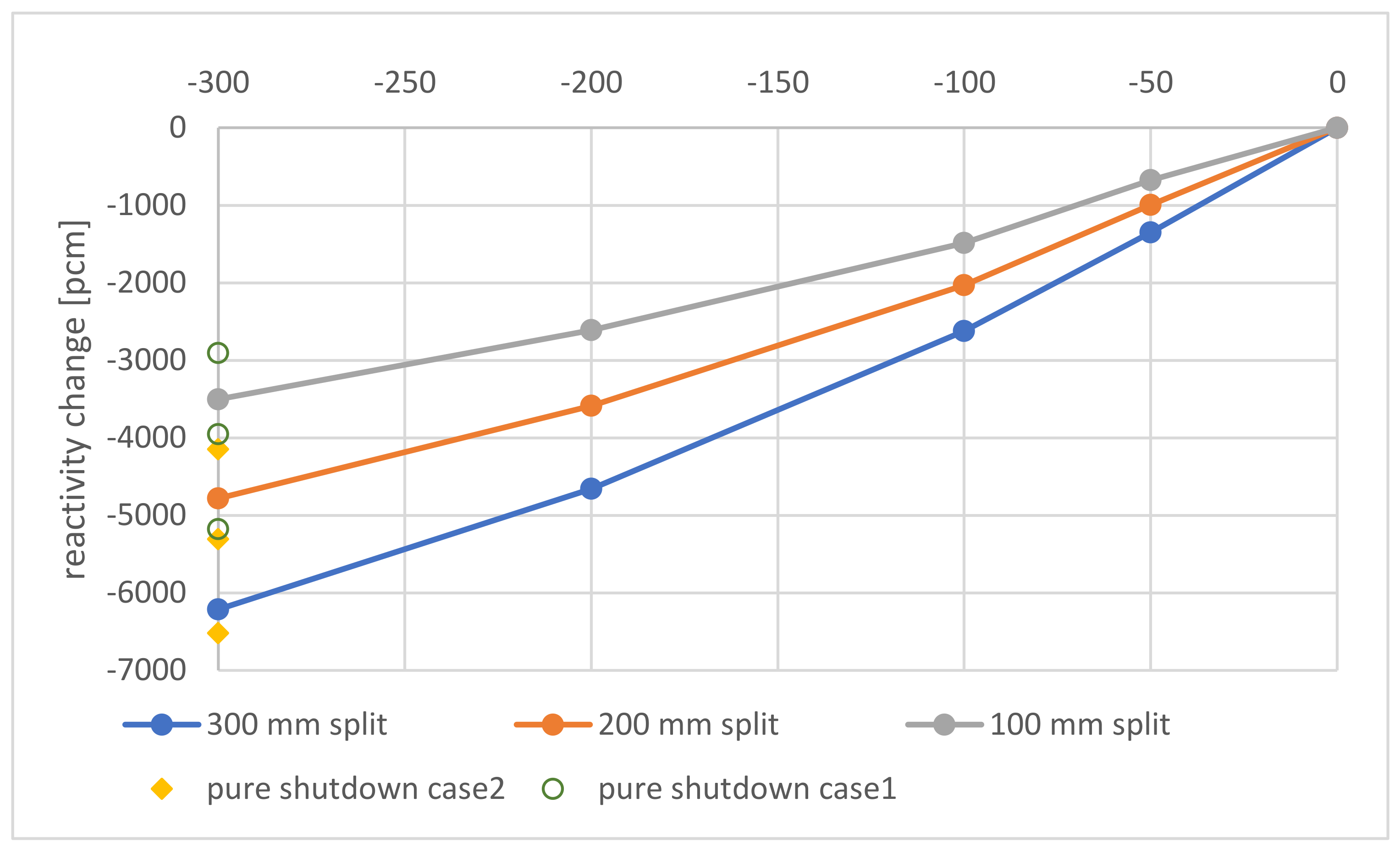
The shutdown reactivity for the three different openings combined with the critical side reflector position is presented in
Figure 14. On first glance, the reactivity change follows the expected pattern with an increasing negative reactivity effect when the width of the opening is increased. The other effect, the increase in the negative reactivity caused by the increase in the core slice split off from the core from a 10 cm-thick slice to a 30 cm-thick slice, coincides with the results presented in
Figure 7. A better evaluation of the absolute values for the 30 cm opening for cases 1 and 2 of
Figure 7 is shown on the left axis. These markers indicate that the combined shutdown and control case can be seen as a type of intermediate solution between the two cases, with the 30 cm-thick core layer split tending to be closer to case 2. In general, the influence of the radial reflector positions does not seem to have a very strong influence on the efficiency of the shutdown system. This finding will be very helpful for the future core design, but to deliver convincing results to the regulator, a study of a wider variety of combinations between the shutdown and the control system position will be required to demonstrate the efficiency of the shutdown system under all possible operational circumstances.
It is essential to understand the interaction of the control system and the shutdown system for any consideration of the safety of a zero-power reactor. However, for reactor design, it is also important to understand, in addition, the effect of the thickness of the reflector on the efficiency of the shutdown system, as shown in
Figure 15. From this figure, it is clear that the reflector thickness does not have a major influence on the shutdown reactivity; thus, there seems to be only a weak interdependence, which is important to know to guide future investigations and to create freedom for the design of a future zero-power reactor core. The most important information is that there is almost no influence of the small openings on the reactivity change. Thus, the shutdown system characteristics shortly after initiation of the shutdown are not affected by the reflector thickness, and even at the very large opening, the effect of the reflector thickness on the shutdown margin is very limited.
Following the investigation of the interaction of the control and shutdown systems, two final points will be investigated for completeness to answer the following questions: Is the control system sensitive enough to compensate for small reactivity changes with a sufficient movement of the reflector? Can the results gained with the multi-group Monte Carlo be trusted, even if the master library of SCALE has been developed for light-water reactor use?
4.4. Sensitivity of the Control System
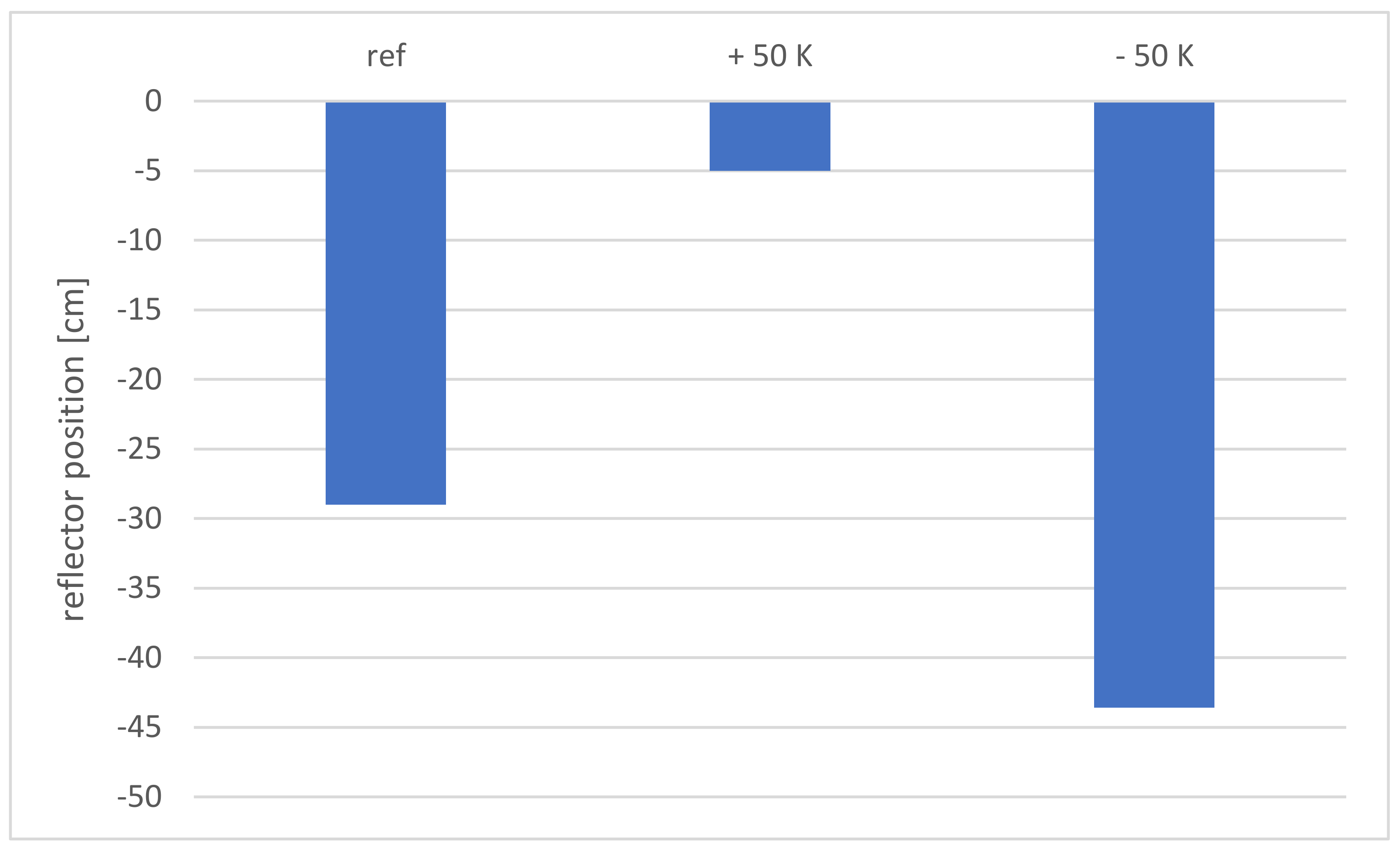
The first test for the sensitivity of the control system is based on the compensation of the thermal feedback when the core temperature will be changed by ±50 °C. The three reflector positions for the investigated reference case as well as for the reduced and increased temperature cases are shown in
Figure 16, with the detailed numbers presented in
Table 2. When the temperature of the core is increased from the reference temperature by 50 °C, the reflector has to be moved upwards to compensate for the reduced density of the fuel as well as for the increased absorption through the Doppler effect. The reflector has to be moved 24 cm upwards for the compensation of the increased temperature, which means that, based on an initial guess, a temperature change of 2 °C will be compensated by a movement of 1 cm within the calculation accuracy of the criticality iteration (±30 pcm) and the accuracy of the Monte Carlo method (±33 pcm at a confidence of 95%). This seems to be a reasonable position change, which can be easily controlled through a modern movement system (comparable to a control rod drive in an LWR), as detected by modern measurement technologies for the determination of the reflector position. However, it has to be kept in mind that the weight of the reflector will be significantly higher than for a control rod group moved by one drive.
The compensation of the cooldown of the core works in a similar manner. When the fuel temperature is reduced, the density of the salt will increase, and the absorption in the fuel will decrease, both leading to a higher criticality of the reactor. To compensate this criticality change, the reflector must be moved downwards by ~14 cm. The required movement is less strong than for the heat-up since the efficiency of the control system is higher at a position closer to the center of the core (see discussion of the control reactivity curve in
Figure 11). Thus, in this case, a temperature change of 2 °C will be compensated by a movement of the reflector by of ~0.6 cm or 6 mm, which is still a value that is reliably detectable. In addition, it should not be forgotten that the temperature in this system is strongly negative, and that the reactor will self-stabilize due to the feedback effect. However, the results shown are for a system with molten salt at a temperature level of ~700 °C. A real reactor physics experiment would most probably be operated at room temperature with a solid core in the first instance to reduce the regulatory challenge by applying a stepwise approach. In this temperature range, the feedback effects in the solid salt eutectic block will be substantially different. Thus, a study based on the effectiveness of the proposed control system at room temperature should be performed as soon as reliable data on the thermal expansion coefficient of the proposed fuel salt in the room temperature range are available.
4.5. Consistency Check of the Multi-Group Monte Carlo Results
To assure the quality and reliability of the results delivered by the multi-group version of KENO-VI using the v7-252 cross-section set of the SCALE package [
25] as a master library for the CSAS-MG cross-section generation procedure, the result for the critical reference case will be compared to a reference continuous energy Monte Carlo solution. The results for the comparison are presented in
Table 3. The application of the continuous Monte Carlo approach delivers a slightly different critical reflector position at −22 instead of −29 cm. The results demonstrate that the use of the weighted master library has some influence on the results, but the influence seems to be limited and of sufficient quality for the delivered scoping study. This justifies the use of the significantly faster multi-group Monte Carlo approach as sufficiently accurate for the current level of this feasibility study. Nevertheless, for future application, a two-fold strategy seems to be indicated using the multi-group approach, with deterministic as well as Monte Carlo approaches, for serial fast track studies to improve the systematic understanding of the system which should be backed up with several continuous energy calculations to justify the absolute values as a reference result for the design. In general, the envisaged zero-power experiments will exactly deliver the validation basis for the future code application to assure a good validation level of the code systems. This is an important step in the case of a new, completely different reactor system. It is essential to demonstrate that code systems developed for other applications, e.g., mainly LWR, can be validated and used for the design of future molten salt reactor systems. However, a first level of modeling and simulation results will be required for the design of a zero-power experiment; thus, the careful use of different tools and databases as well as critical analysis of the differences will be required in the same way as the improvement in the thermo-physical data as input for the modeling and simulation tools. Thus,
Table 3 provides a first insight into what quality of the results and which deviations have to be expected, and thus it points out the importance of validation experiments for quality assurance in the modeling and simulation of innovative reactor systems.
5. Summary and Conclusions
The topic of control and shutdown was introduced through a literature review and a reduction in the control approaches to a limited number of basic functions with different variations. In this study, the requirements for the control and shutdown systems for a reactor experiment were formulated, and based on these, an approach for the shutdown, i.e., splitting the lower part of the core with the reflector, and an approach for the control, i.e., a vertically movable radial reflector, were proposed. Both systems are usable for a zero-power system with a liquid as well as a solid core, and even more importantly, both systems somehow work at the integral system level and do not require the central part of the core to be disturbed, which will be the essential area for the experimental measurements. Both approaches, as singular systems, as well as their interaction, and the sensitivity of the control system were investigated through the use of a multitude of modeling and simulation results using deterministic and Monte Carlo tools of the SCALE package.
The investigation of the shutdown efficiency assessed it between only moving the reflector and moving the reflector with increasingly sized layers of the core up to 30 cm. The comprehensive study indicated a variety of solutions, with a shutdown reactivity effect from −2000 up to −8000 pcm, depending on the configuration.
The analysis of the proposed control approach was evaluated against the U-235 to indicate the control span with increasing U-235 enrichment, which was followed by the investigation of the control curve for the standard system delivering a control span of −18,000 pcm. The sensitivity investigation was based on a variation of the reflector thickness by ±10 cm, which led to a variation of ~±20% in the control span, based on the slight core size variations resulting from the effect of changes to the reflector thickness. A control reactivity curve dependent on the stepwise downward movement of the reflector for systems with different thicknesses of the reflector was provided for all cases and the neutron spectrum change between the core with a reflector (lower core part) and without a reflector (upper core part).
The interaction between both systems was analyzed by introducing a shutdown with different openings in conjunction with the reflector control system being in the position of a critical system delivering a shutdown reactivity curve with a maximum between −3500 pcm for a 10 cm layer and −6200 pcm for a 30 cm layer. The dependence of the shutdown system on the system size change due to the change in the reflector thickness was found to be marginal. A sensitivity study based on a system temperature change of ±50 K led to a reflector movement of +24 cm for +50 K and −14.6 cm for −50 K to compensate for the related reactivity change induced by the temperature change.
Finally, a consistency check between the multi-group Monte Carlo result, as used for this study, and a continuous energy Monte Carlo result using the same cross-section basis of SCALE was presented, which indicated a small change in the predicted control position. This inter-comparison of codes of the SCALE package with good agreement between them creates trust in the results obtained but indicates that there is room for improvement and demonstrates the need for validation experiments to assure the best possible results for future modeling and simulation of molten salt reactor systems.
The current analysis was only applied to a very narrow window of operational temperatures in molten salt, which is related to the limited data availability. Thus, a much more comprehensive study will be required as soon as the relevant thermo-physical properties are available down to room temperature. Both approaches, the control through the movement of the reflector, and the shutdown through moving a layer of the core, require mechanical movement of core pieces with a significant mass. Thus, there is a clear requirement for the design of equipment which is able to reliably move large masses with a reasonable accuracy and an acceptable speed for a rapid reactivity reduction in the case of an incident.


 ,
, 


