Article

3D Interpreted Model: A Novel Product Definition Model by Integrating and Fusing a 3D Annotated Model and Design Knowledge

1
School of Mechanical Engineering and Automation, Beihang University, Beijing 100191, China
2
Sub-Institute of High-Tech Standardization, China National Institute of Standardization, Beijing 100191, China
*
Author to whom correspondence should be addressed.
Appl. Sci. 2021, 11(16), 7192; https://doi.org/10.3390/app11167192
Submission received: 12 July 2021 / Revised: 30 July 2021 / Accepted: 2 August 2021 / Published: 4 August 2021

Abstract

:

Featured Application

One potential application is to solve the problem of propagation reasoning and assistant decision-making of product technical information change. When designers change a certain size or technical information of the product, the product information that needs to be changed synchronously can be found by studying the corresponding information change propagation mechanism, and the corresponding design knowledge can be provided to support designers in making decisions.

Abstract

Model based definition (MBD) is the core of product digital research and development. The extension of the scope and content of the product model is an important way to improve the application ability of MBD methodology. In view of the demand of the development of the product definition method and the lack of systematic theoretical methods to support the further improvement of product model quality and ability, this paper proposes the concept of a 3D interpreted model as a new product definition model by integrating and fusing design knowledge on the basis of the MBD model. Firstly, the concept, characteristics and representation method of the 3D interpreted model are elaborated. Then, the construction method of the 3D interpreted model is proposed, which includes two steps. The first step is design knowledge annotation, which is used to integrate design knowledge with the MBD model and form the 3D interpreted model in a CAD environment. The second step is information extraction and knowledge fusion, which is used to construct a 3D interpreted model network by processing the product information and design knowledge stored in a STEP file and knowledge index file, respectively. Finally, a prototype system is developed, and the construction process of a 3D interpreted model is demonstrated and verified through an example. The results show that as a new product definition model, a 3D interpreted model realizes the comprehensive integration of a MBD model and design knowledge, so as to realize the inheritance and development of the product definition method, and supports business activities and saves more social resources.

1. Introduction

There are a large number of product research and development tools in various stages of product lifecycle, such as demand, design, manufacturing, operation and maintenance, which produce a large number of product design and manufacturing data and lead to an information island problem between these tools and data [1]. Model based engineering (MBE) is an important methodology to solve the problem of product life cycle data integration and sharing. It realizes the seamless and rapid flow of product information in the whole lifecycle, and ensures the traceability of product information [2]. The core of MBE is a methodology-named model-based definition (MBD). Furthermore, the connotation of MBD is to establish a single data source that completely describes the product information and use the single data source as a basis for subsequent business stages. Relevant research shows that MBD helps to further shorten the product research and development cycle and improve product quality [3,4].
As a way of product information definition and description, MBD method is produced with the continuous development of computer technology. Generally speaking, the definition and description of product information can be summarized into three stages: the 2D electronic drawing stage, 3D geometric model stage and MBD stage:
  • Before the advent of 3D modeling technology, product geometric information and technical information are expressed on the 2D electronic drawing with default rules and forms, and the complete description of the product is realized through the combination of multiple drawing views of the product. Therefore, this period is called the 2D electronic drawing stage, which is difficult to describe the product geometry intuitively and accurately;
  • In order to solve this problem, 3D modeling technology came into being, and the way of product description gradually changed to a combination of 3D geometric model and 2D electronic drawing. The 3D model can directly and vividly express the product geometric information, and the technical information needed in the manufacturing process is still transferred by means of 2D electronic drawing. This situation leads to problems such as different information sources, inconsistent product information and the difficulty of product information maintenance;
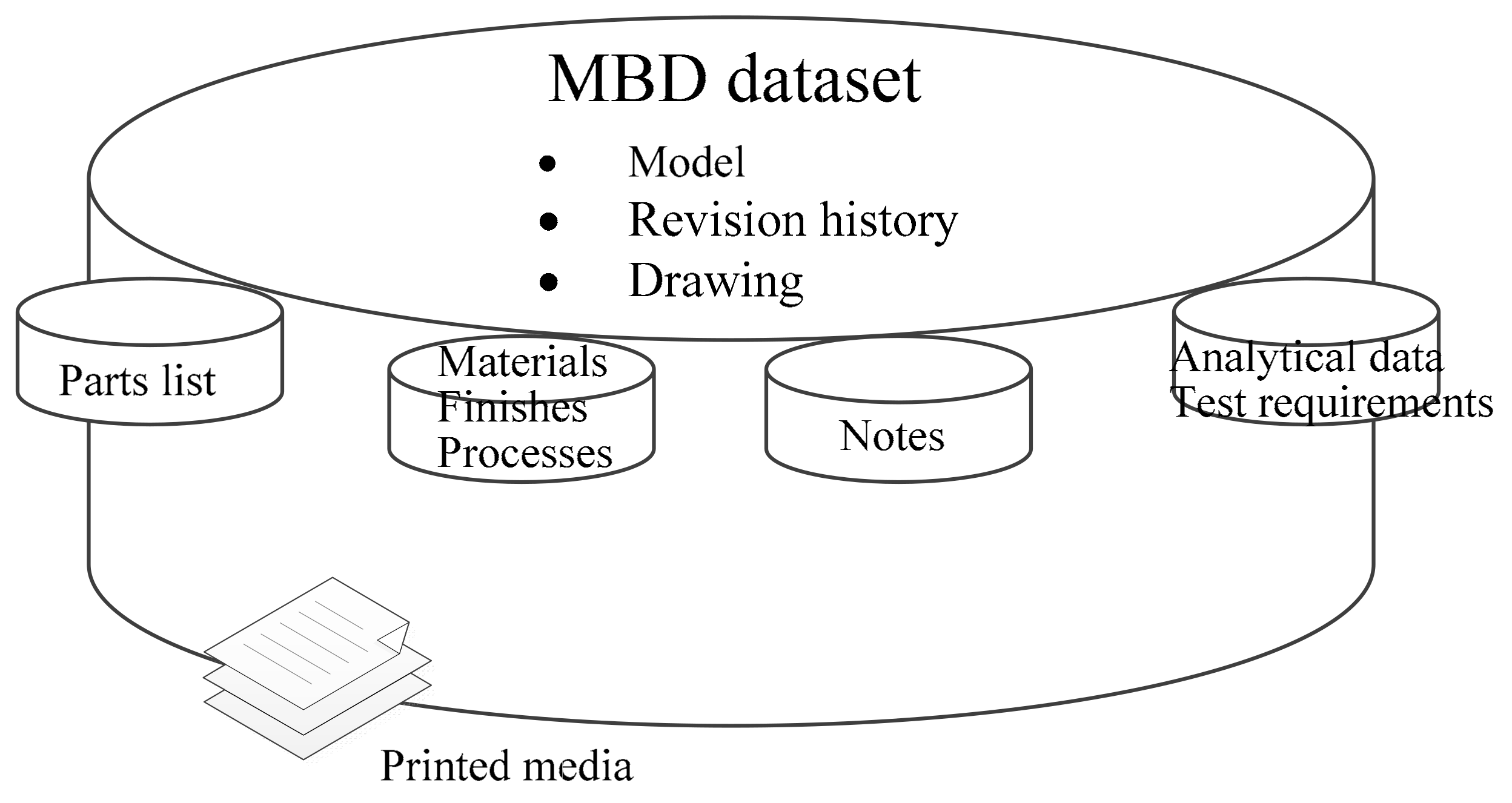
  • In order to ensure the information consistency, MBD is proposed as a methodology to realize full 3D digitization. The core idea of MBD methodology is to integrate the engineering technical information existing in the 2D electronic drawing into the 3D geometric model, and form the dataset that can completely define the product. Because the product definition dataset contains all the design and manufacturing information, it can completely replace the 2D electronic drawings and ensure the data singleness.
MBD methodology has been applied in aerospace, marine equipment, automobile and other industries. However, further application of MBD methodology still needs in-depth research on data acquisition and visualization, data content expansion and data expression [5].
In terms of MBD dataset content expansion, Camba et al. [6] pointed out that the explicit expression of geometric design intent is important to improve the quality of product model and expand the application ability of MBD. Therefore, an extended annotation model is proposed, which explicitly annotate geometric design intent onto product model. The integration of geometric design intent and geometric information can improve the quality of product model. However, the technical information in product model is not considered, that is, the model proposed by them cannot explain the technical information, which is not only an indispensable part of the MBD model, but also the key information in process planning and manufacturing. In addition, from the perspective of product design, the design intent is only the initial input of product design, and cannot describe the design decision-making process and design options. Therefore, the model cannot describe the whole design process. In fact, as a 3D model is the core of the design and manufacturing process, Lundin et al. [7] believe that the 3D model is the best carrier for storing and reusing knowledge, and propose a knowledge sharing and reuse framework. They studied the knowledge sharing and reuse framework based on 3D geometric model, but did not answer the question of how to integrate and fuse design knowledge with 3D geometric model. Furthermore, their research object is 3D geometric model, thus the methods studied cannot be fully applicable to MBD model. The integration and fusion of design knowledge and product model will be more complicated in a MBD circumstances, because the MBD model contains more kinds of product information than 3D geometric model and the relationship between information is more complex.
Therefore, this paper studies the integration and fusion of design knowledge and product model under the MBD methodology environment. Facing all types of design knowledge such as design intent, design justification, design decision and design option, a new product definition model, namely a 3D interpreted model is proposed, which integrates and fuses product geometric information, technical information and design knowledge. At the same time, the expression and construction methods of the 3D interpreted model are studied to form a complete method system. In order to verify the effectiveness of the proposed model and method, this paper develops the corresponding 3D interpreted model construction tool based on CATIA, and takes the MBD model in NIST MBE PMI validation and performance testing project [8] as the tool input. After the 3D interpreted model is constructed, the 3D interpreted model is stored in the graph database Neo4j. The main contribution of the proposed method is summarized as the following two aspects: (1) the proposed 3D interpreted model contains more extensive and fine-grained design knowledge, which not only explains the product geometric information, but also supports the explanation of roughness, tolerance and other technical information; (2) on the basis of improving the existing 3D model knowledge annotation method, the construction method of the 3D interpretation model network is proposed. The 3D interpreted model is expressed as a form that can be directly recognized and processed by computer, so as to promote the automatic and intelligent application of the 3D interpreted model. The objective of this paper is to form a new product definition model and its systematic theoretical methods. The new product definition model can explain and interpret the product geometric and technical information at the same time, and contains the design knowledge that completely describes the design process. It is of great significance to further improve the quality of product model and support the sharing and reuse based on product model. At the same time, systematic theoretical methods can guide engineers to carry out specific 3D interpreted model construction and expression.
The rest of the paper is organized as follows: Section 2 gives the related research of MBD methodology and design knowledge classification and representation. Section 3 discusses the definition, connotation and expression of 3D interpreted model. Section 4 presents the construction method of 3D interpreted model. Section 5 presents a case study to verify the proposed method and Section 6 analyzes the experimental results. Section 7 gives the conclusion and future work.

2. Related Works

2.1. Model Based Definition

With the rapid development of digital design and manufacturing technology, the 3D model plays an increasingly important role in product design, manufacturing, maintenance and recycling [9]. Especially in the product design and manufacturing stage, the 3D model has gradually replaced the 2D engineering drawing [10]. Automobile, aviation and other industries have carried out the exploration of full 3D digitization, and gradually formed the MBD methodology. MBD integrates geometric information, design information, simulation analysis information and manufacturing information with 3D model in the form of dataset. In order to further support the application of MBD, the American Society of Mechanical Engineers (ASME) formed the digital product definition data practices ASME Y14.41-2003 [11] in 2003, and revised it in 2012 to form ASME Y14.41-2012. The International Organization for Standardization (ISO) drew up the technical product document—digital product definition data practices ISO 16792-2006 in 2006 by referring to ASME Y14.41 [12].

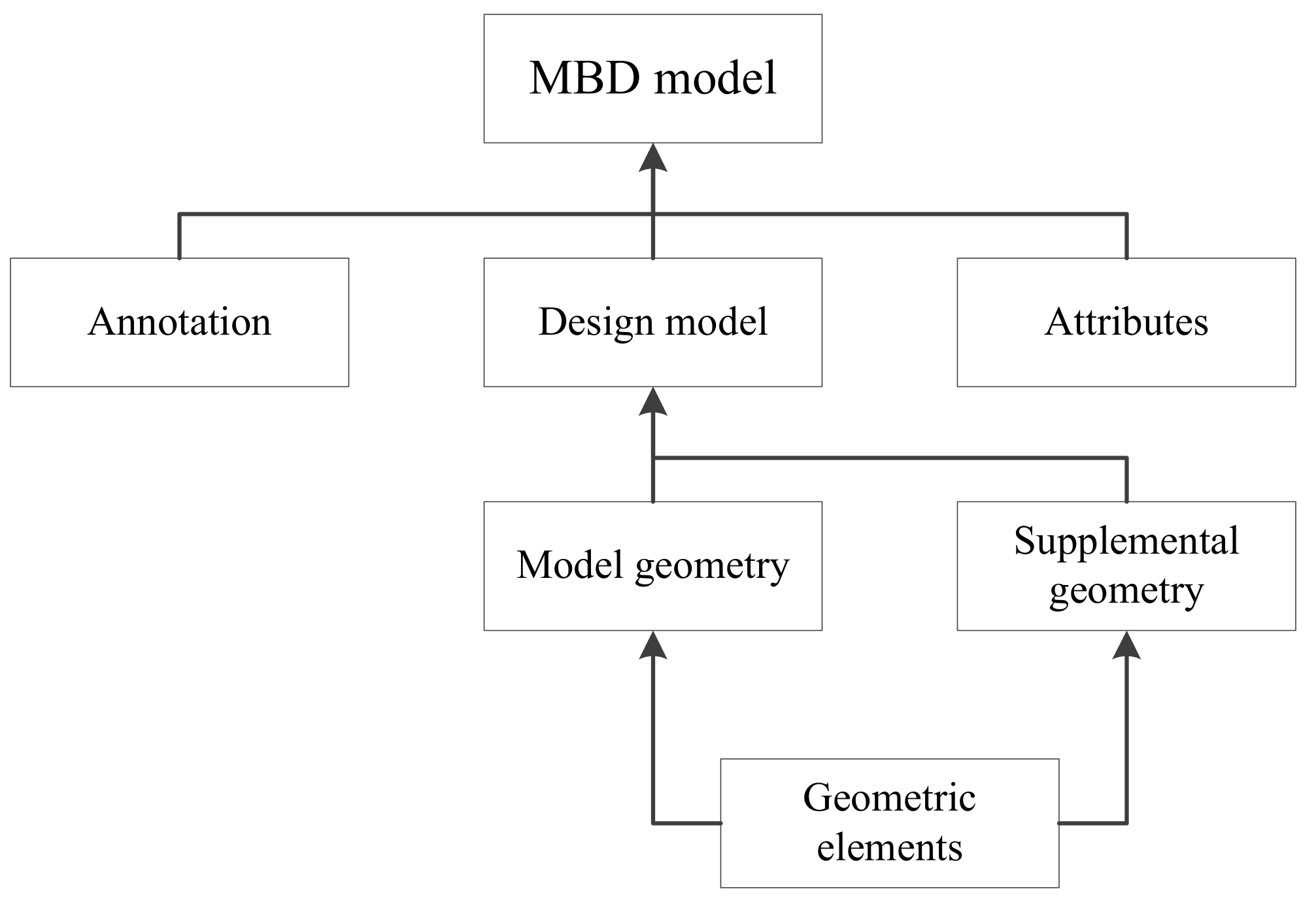
2.1.1. Content of MBD Dataset

The MBD dataset gives a complete definition of products from different perspectives. Figure 1 shows the content of MBD dataset specified in ASME Y14.41-2003. The basic content of the MBD dataset includes a model, revision history and engineering drawing. In addition, it also includes parts list, materials, finishes and processes, notes, analytical data, test requirement and related print media. Because the classification of MBD dataset in the standard is universal and general, it is difficult to directly meet the application in specific fields. Therefore, Ruemler et al. [13] studied the general information of design, manufacturing, quality and other lifecycle stages, and supported the establishment of public information model for product lifecycle. Huang et al. [14] proposed a multi-level structured MBD model to improve the manufacturing reusability of parts.
The model in the MBD dataset is different from the 3D geometric model. It is the result of integrating technical information into the 3D geometric model. The technical information includes geometric dimensions, tolerances and roughness. The content of this MBD model is shown in Figure 2, in which the design model refers to the geometric definition and auxiliary geometry of the product. Annotation refers to the dimensions, tolerances, roughness and various text descriptions displayed on the model. Attributes refer to the dimensions, tolerances, notes, text or symbols needed to completely define products or features, which can be obtained by querying the model.

2.1.2. Presentation and Representation of MBD Dataset

ASME Y14.41 and ISO 16792 mainly specify the content of MBD dataset and the display mode of product Geometric Dimensioning and Tolerancing (GD and T) in 3D environment, while ASME Y14.9 [15] and ISO 1101 [16] specify the syntax and semantics of GD and T. These standards solve the problem of user oriented presentation of GD and T, and provide the basis for the application of MBD methodology. However, in order to truly support the deep application of MBD in the industry, the problem of computer expression of MBD dataset must be solved. Only by expressing MBD dataset as information that can be recognized and processed by computer, can MBD support the realization of 3D digital design and manufacturing.
Therefore, based on the existing application protocol (AP) parts 203 and 214 of the Standard for the Exchange of Product Model Data (STEP), ISO has formulated AP242 to meet the application of MBD methodology with STEP as the intermediate format [17]. As another application protocol, AP242 also specifies the presentation and representation of GD and T [18], so different CAD systems can access and interact with the MBD dataset through intermediate format STEP files. STEP standard develops EXPRESS language to express the geometric and technical information in MBD dataset, introduces the concepts of ENTITY and SCHEMA and stores the information according to ASCII to form a common. STP file, also known as P21 file [19].
The establishment of AP242 provides an important support for the application of MBD methodology in the case of using STEP as the neutral format, but AP242 also has some limitations. On the one hand, STEP is mainly oriented to the detailed design stage. When it is oriented to the whole product lifecycle, it is difficult to integrate with the product information models constructed by other modeling languages. Therefore, on the basis of STEP, Barbau et al. [20] proposed an OntoSTEP model to integrate the product information expressed by multiple modeling languages. On the other hand, although AP242 specifies the representation of MBD model in detail, the mainstream CAD software such as CATIA, UG NX and CREO only supports AP242 edition1 [21] version at present, which uses fragmented and tessellated geometric set to store annotation information and cannot retain the semantics of technical information.

2.2. Classification and Representation of Design Knowledge

Design knowledge is the most important intellectual resource generated and applied in the process of product research and development. Design knowledge is crucial for enterprises to improve product performance and quality [22]. Design knowledge has different classification from different dimensions.
From the dimension of application object, design knowledge can be divided into declarative knowledge, contextual knowledge and process knowledge [23]. Declarative knowledge is used to clarify the subject, object, tools and methods used in design. Process knowledge is used to describe the execution process of design. Furthermore, context knowledge is used to describe the conditions and states to perform product design (know when, where and why).
From the dimension of the existing form, design knowledge can be divided into tacit knowledge and explicit knowledge. Tacit knowledge is the knowledge that exists in the brain of designers and may not be described and recorded. Explicit knowledge is the formal knowledge existing in certain physical form. These physical forms are summarized as pictorial, symbolic, linguistic, virtual and algorithmic [24].
From the substantive dimension of product design, product design is an iterative process of transforming design intent into product functions, behaviors and structures. The knowledge of explaining the design decision-making process is called design rationale knowledge [25]. Therefore, the division of design knowledge can also be carried out from the dimension of design rationale knowledge elements. There are many different representation models of design rationale knowledge, and different design rationale knowledge elements are included in different representation model. For example, the Issue based Information System (IBIS) model consists of three design rationale knowledge elements: issue, position and arguments [26]. Issue Solution Artifact Layers (ISAL) model is divided into issue layer, solution layer and artifact layer [27], which has the ability to describe the product compared with IBIS. However, the evolving design rationale model [28], which is driven by design intent, divides the elements into design intent, decision justification, design decision and design operation.
In fact, design knowledge classification does not form a unified standard. Besides the above typical classification methods, design knowledge can also be classified according to the actual business requirements.

3. 3D Interpreted Model

The reason why MBD methodology can be widely used depends on the support of relevant standards in MBD model content, presentation and representation. Similarly, the integration and fusion of product model and design knowledge to form a new product definition model, the content and presentation method of such a new product model should also be expounded. Therefore, this part focuses on the concept of the 3D interpreted model, and expounds the relationship between the 3D interpreted model, 3D annotated model, and extended 3D annotation model proposed in [6], and finally gives the representation structure of 3D interpreted model.

3.1. Definitions and Characteristics

The MBD dataset is used to completely define the relevant dataset of products, the core of which is the product model named MBD model. The MBD model includes a design model (3D geometric model) and its associated annotations and attributes. Among them, design model is the 3D graphical representation of product model; annotations refer to the dimensions, tolerances, notes and datum directly displayed in the 3D environment; and attributes are the information equivalent to annotations in content, but its form is text description and table. Because the product manufacturing information is integrated into the design model mainly by annotations and supplemented by attributes, the MBD model can be defined as 3D annotated model, and the product model formed by the integration and fusion of 3D annotated model and design knowledge is defined as 3D interpreted model. The overall process of product model developing from 3D geometric model to 3D interpreted model is shown in Figure 3.
Definition 1. 
3D Annotated Model (3DAM). 3D annotated model is a kind of product model, which takes the explicit annotation of product technical information in 3D environment as the main means, supplemented by a certain way of implicit information interaction, and can completely describe and define the geometric and technical information of a product.
3DAM can be represented as follow.
3 D A M = I N F g , I N F t
where, I N F g represents the product geometric information, such as model, surface, edge, etc.; I N F t represents product technical information, such as dimensions, tolerances, roughness, datum, etc. In the 3DAM stored in STEP, the geometric information is mainly combined into model geometry by boundary representation (B-rep). For example, the shape of the model is composed of faces and the face is composed of edges. The integration of technical information with geometric information is realized by forming a large number of association groups. For example, the feature control frame forms the association group with the controlled feature through arrows.
3DAM has the following characteristics:
  • Information integrity. Information integrity means that product geometric information and technical information can completely define the product, and there is no missing or redundant product information.
  • Information consistency. Information consistency means that there is consistency between product technical information and there is no mutual exclusion between technical information.
Definition 2. 
3D Interpreted Model (3DIM). The 3D Interpreted Model is a kind of product model formed by integrating and fusing product design knowledge on the basis of 3DAM, which can not only describe and define product geometric and technical information completely, but also integrate and control the design knowledge hidden behind product geometric and technical information.
3DIM has richer and more accurate semantic information and resource and can be represented as follow.
3 D I M = 3 D A M D K = I N F g , I N F t , D K
where, I N F g represents product geometric information; I N F t stands for product technical information; DK represents design knowledge. In this paper, design knowledge refers to the intellectual elements hidden behind the product model, such as design intent, design justification, design decision and design option.
D K = D I , D J , D D , D O
where, DI refers to design intent; DJ refers to design justification; DD refers to design decision; and DO refers to design option. The specific meaning and examples of each type of design knowledge are shown in Table 1.
Due to the integration and fusion of design knowledge in 3DAM, 3DIM contains not only the geometric and technical information as the final result of product design, but also the design knowledge hidden behind the geometric and technical information, which is used to further explain the geometric and technical information. Therefore, 3DIM has the following characteristics:
  • Information integrity. Information integrity is the same as 3DAM;
  • Information consistency. Information consistency is the same as 3DAM;
  • Information intelligibility. Information intelligibility means that product model not only describes what product information is, but also describes why product information should be designed in this way, how to produce such design results, and what is the design space of product information, making product information easier to understand.

3.2. Differences between Relevant Product Definition Model

In order to better explain the relationship between 3DAM, 3DIM and extended annotation model (EAM) proposed in literature [6], this paper compares these related models from the perspective of product model content, as shown in Figure 4.
Two conclusions can be drawn from the figure.
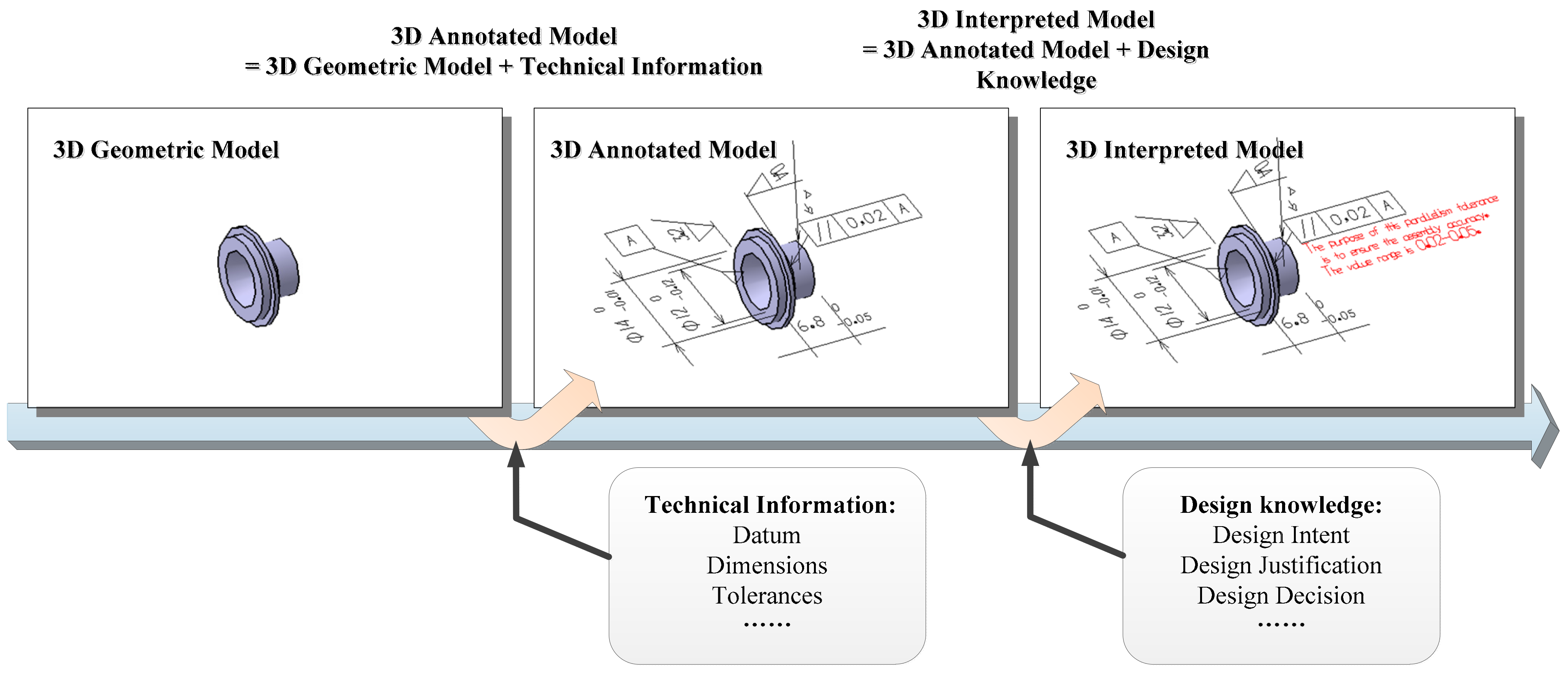
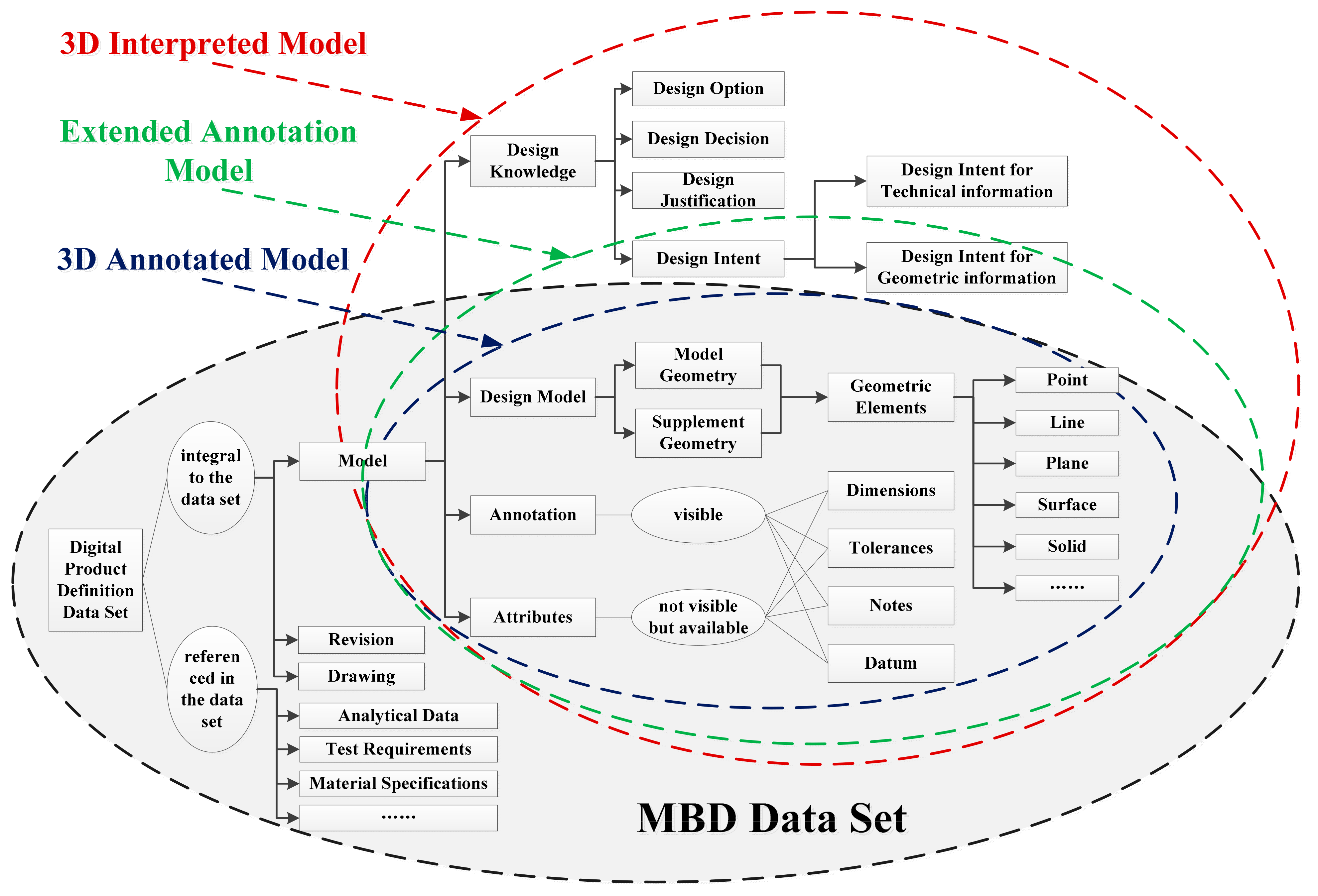
  • 3DAM is a part of MBD dataset about product model, and also a part of 3DIM about product geometric and technical information. That is to say:
3 D I M M B D d a t a s e t = 3 D A M
  • Both 3DIM and EAM are product definition models formed by the integration and fusion of 3DAM and design knowledge. The main difference is that 3DIM has more complete design knowledge than EAM, that is, design knowledge includes not only the design intent of geometric information, but also the design justification, design decision, design option and design intent oriented to technical information. The differences of 3DAM, 3DIM and EAM can be expressed as follows:
3 D I M = 3 D A M D I , D J , D D , D O
E A M = 3 D A M D I g
3 D I M = E A M D I t , D J , D D , D O
On the basis of 3DAM, how to describe the relationship between design knowledge product information, and how to organize these information and knowledge to form the representation structure of 3DIM will be described in Section 3.3.

3.3. Representation of 3D Interpreted Model

As the carrier of information and knowledge in product research and development process, 3DIM needs to represent the information and knowledge contained in the model in order to play a further role. Because MBD-related standards have stipulated the computer presentation way of product geometric information, technical information and the relationship between them, this paper focuses on solving the problem of representation of design knowledge and product information.
Figure 5 shows the representation structure of 3DIM. It can be seen that 3DIM contains three types of child nodes: geometric information, technical information and design knowledge. Among them, geometric information and technical information form association group through auxiliary geometry, and design knowledge interprets and describes geometric and technical information. Therefore, the relationship among these three types of child nodes can be described as three tuples: <Technical Information, associated-to, Geometric Information>; <Geometric Information, interpreted-by, Design Knowledge>; <Technical Information, interpreted-by, Design Knowledge>.
At the same time, each kind of design knowledge is composed of design intent, design justification, design decision and design option, and each kind of design knowledge has different physical carriers. Therefore, design knowledge can be described as three tuples: <Design Knowledge, divided-into, Design Knowledge Type>; <Design Knowledge Type, carried-by, Physical carrier>.
Design Knowledge Type = {Design Intent, Design Justification, Design Decision, Design Option}; Physical carrier = {Pictorial, Symbolic, Linguistic, Virtual, Algorithmic}.

4. Construction of 3D Interpreted Model Network

The definition and representation of 3DIM are described above. This section focuses on solving the following problems: how to construct 3DIM based on 3DAM, and realize the computer representation and storage of 3DIM, so as to support the further application.
In this paper, the concept of a 3D interpreted model network is used as the computer representation and storage way of 3DIM. This network is an instantiated representation structure proposed in Section 3.3. One 3DIM corresponds to one 3D interpreted model network. The overall construction process of 3D interpreted model network is shown in Figure 6. Firstly, design knowledge resources and the 3D annotated model are integrated to form the 3D interpreted model by the design knowledge annotation method, and knowledge index files describing design knowledge and product information are generated. At the same time, P21 files describing product geometric and technical information are exported by CAD software. Then, the geometric information, technical information and the association group of geometric and technical information are extracted from the P21 file. Furthermore, the product information is fused with the design knowledge recorded in the knowledge index file to form a 3D interpreted model network. In this method, design knowledge annotation, information extraction and knowledge fusion are key steps. The specific implementation process is described below.

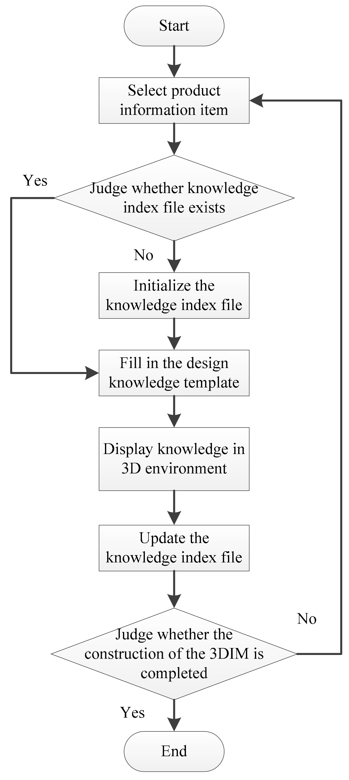
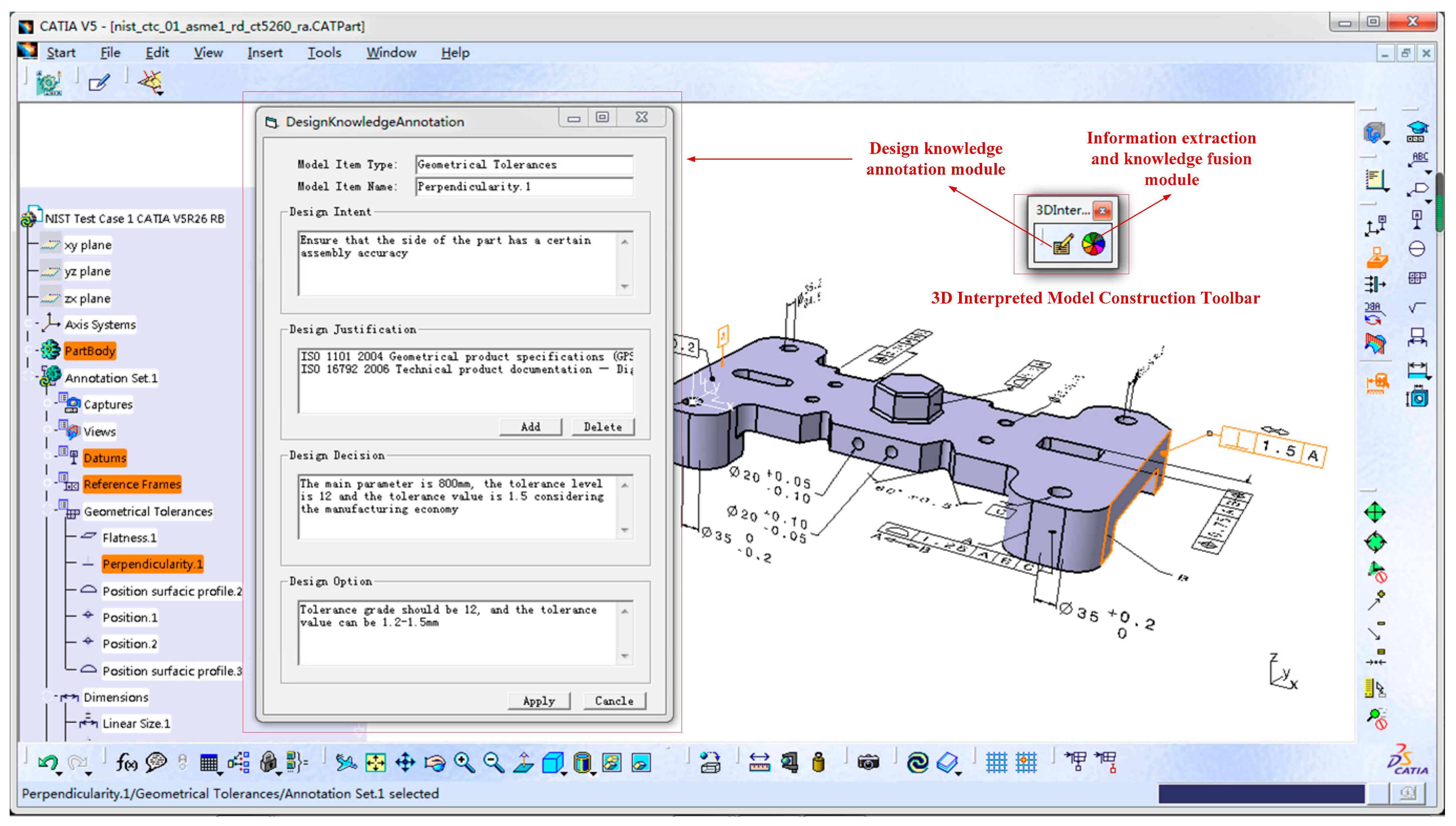
4.1. Design Knowledge Annotation

Design knowledge annotation is a process to integrate product information with design knowledge. Similar to the annotation process of product technical information, the annotation process of design knowledge is usually led by designers, and needs to use certain tools to achieve the interaction between designers and product model. Because the design knowledge annotation object of 3DIM contains both product geometric information and technical information, design knowledge has many different types. Therefore, this paper proposes a general process of design knowledge annotation for 3DIM based on literature [6] and improves the annotation object uniqueness and design knowledge display strategy. The process of design knowledge annotation is shown in Figure 7 and the corresponding algorithm is shown in Appendix A.
In the process of design knowledge annotation, the core is the design of knowledge index file structure. The knowledge index file can not only record the relationship between product information and design knowledge, but also record the knowledge content in the design knowledge template. In this paper, the extensible markup language (XML) is used to build the knowledge index structure as shown in Figure 8. The area shown by the red line in the figure is the content of the design knowledge template of the technical information “linear size.1”. In the knowledge index file:
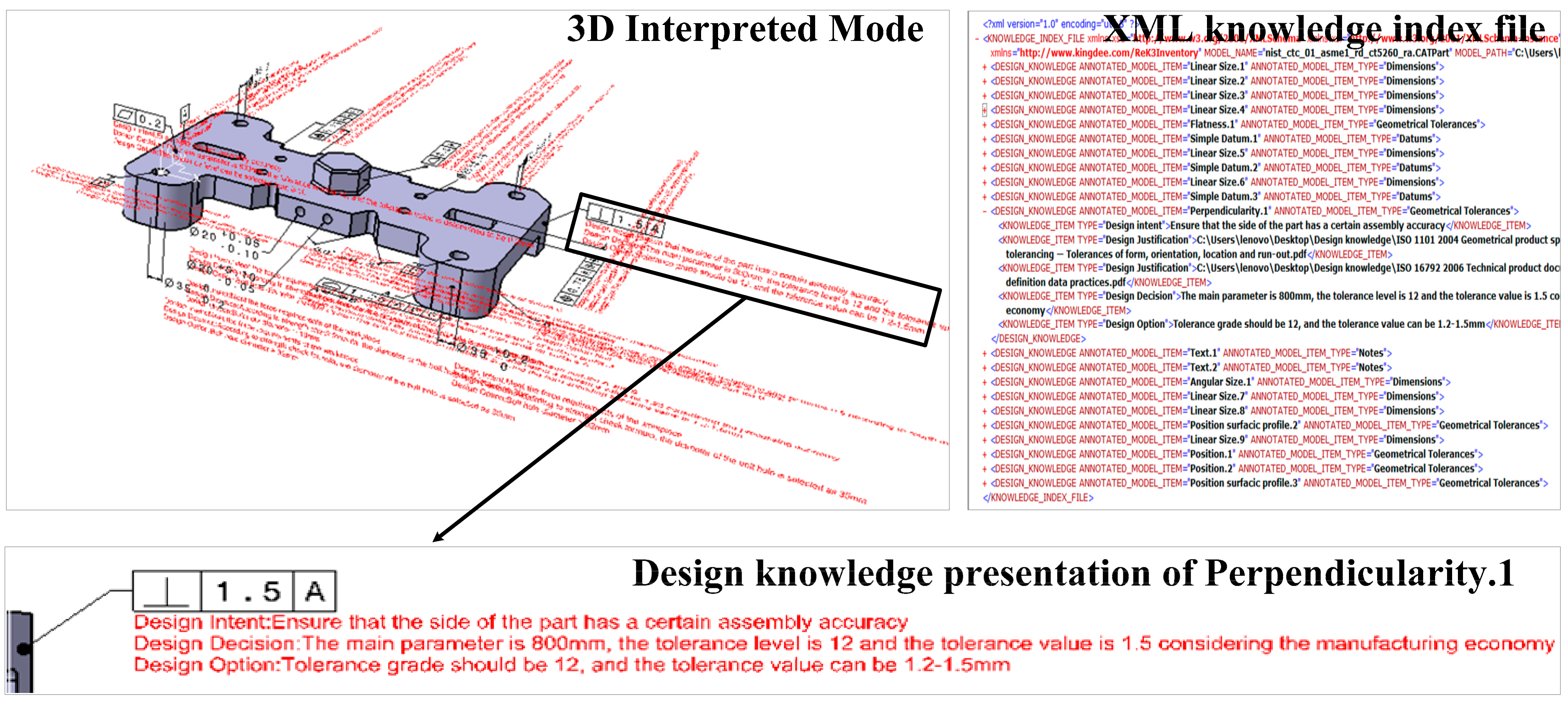
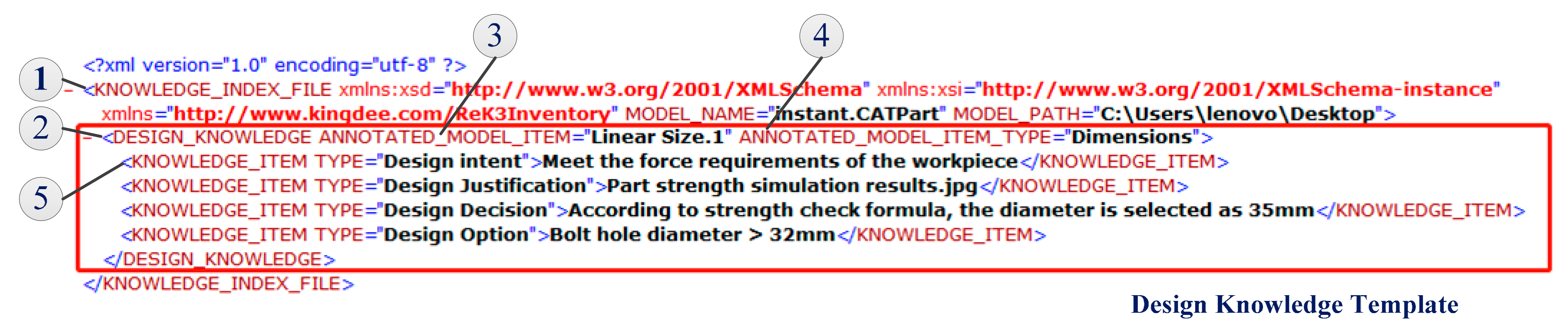
  • The root node KNOWLEDGE_INDEX_FILE contains the name, path and other basic attributes of the product model, so each knowledge index file corresponds to one product model;
  • Child node DESIGN_KNOWLEDGE is used to record the knowledge content in each design knowledge template;
  • ANNOTATED_MODEL_ITEM is an attribute of DESIGN_KNOWLEDGE. The value of ANNOTATED_MODEL_ITEM is the unique identifier in the product model, which is used to solve the problem of information mapping between P21 file and knowledge index file in the process of information extraction and knowledge fusion.
  • ANNOTATED_MODEL_ITEM_TYPE is another attribute of DESIGN_KNOWLEDGE.
  • KNOWLEDGE_ITEM is the child node of DESIGN_KNOWLEDGE, which represents each knowledge item and has different types such as design intent, design justification and so on.
Figure 8. The structure of knowledge index file.
Applsci 11 07192 g008

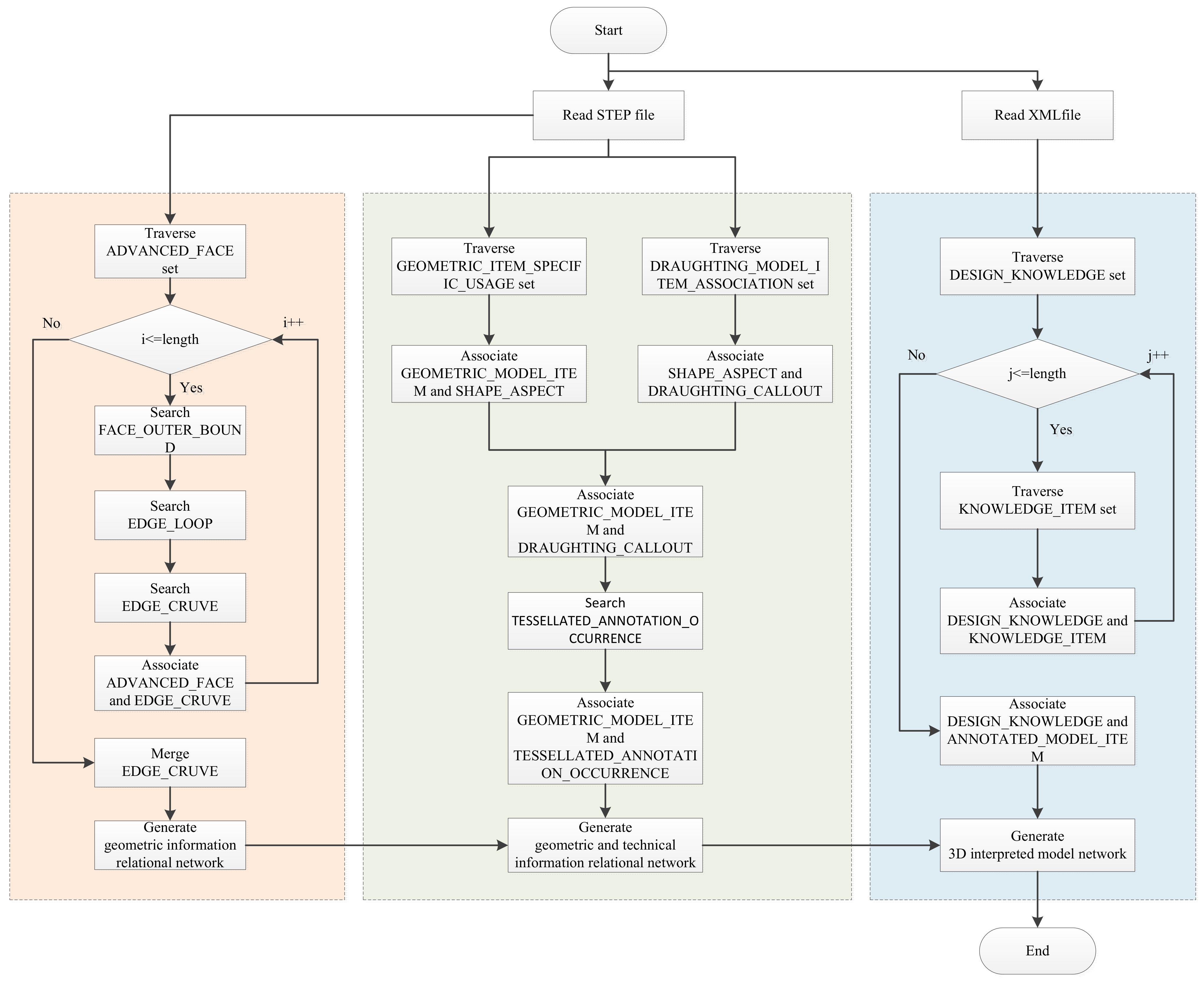
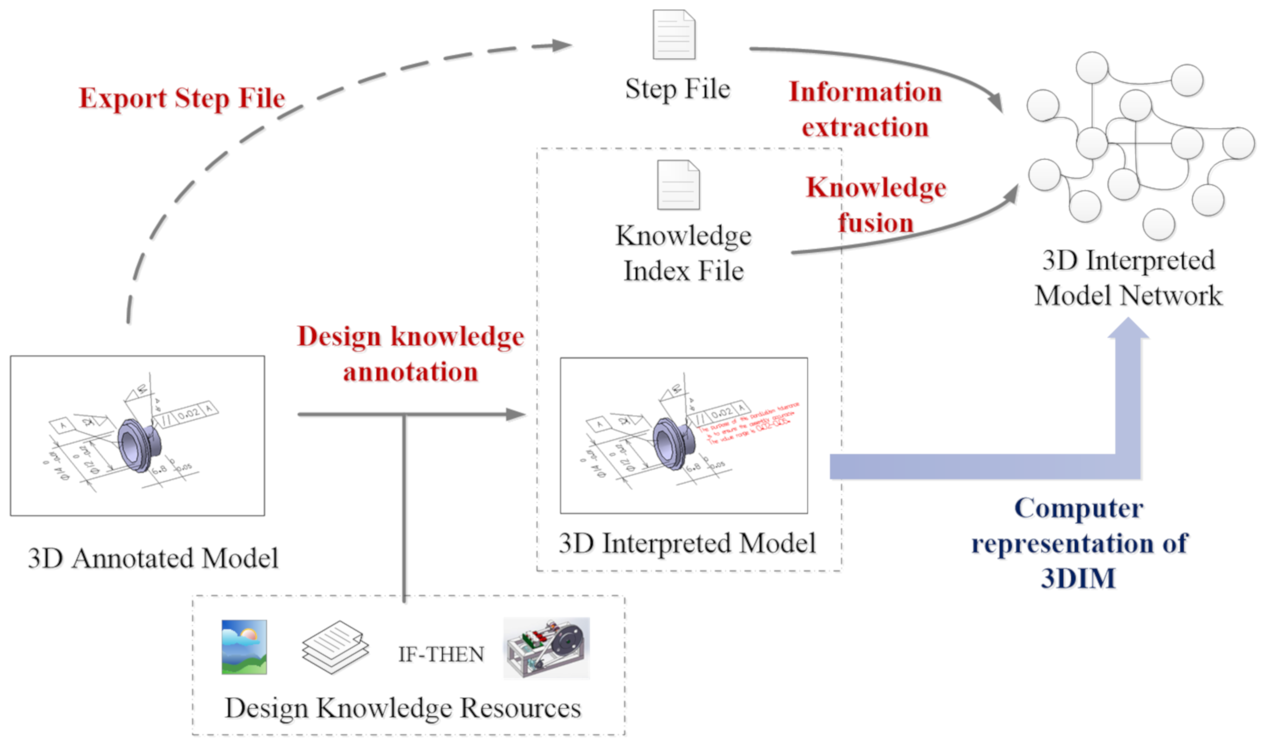
4.2. Information Extraction and Knowledge Fusion

The mainstream CAD software mainly uses AP242 edition1 version to realize the storage of 3D annotation in STEP file by means of tessellated data, which cannot retain the semantics of technical information. Therefore, this paper proposes the corresponding information extraction and knowledge fusion algorithm to extract geometric and technical information from this kind of STEP file. The proposed algorithm forms the geometric information relational network, the geometric and technical information relational network in turn. Furthermore, through the processing of XML knowledge index file, the construction of 3D interpreted model network is realized. The specific process is shown in Figure 9.
Step 1: extract geometric information relation. Traverse all ADVANCED_FACE in the STEP file as the child node of CLOSED_SHELL. Based on each ADVANCED_FACE, search FACE_OUTER_BOUND, EDGE_LOOP, ORIENTED_EDGE and EDGE_CRUVE in turn to establish the relationship between ADVANCED_FACE and EDGE_CRUVE. Merge the same EDGE_CRUVE nodes to generate the geometric information relational network;
Step 2: extract the relationship between geometric and technical information. Traverse GEOMETRIC_ITEM_SPECIFIC_USAGE to associate SHAPE_ASPECT and GEOMETRIC_MODEL_ITEM (ADVANCED_FACE or EDGE_CRUVE). Traverse the DRAUGHTING_MODEL_ITEM_ASSOCIATION to associate SHAPE_ASPECT and DRAUGHTING_CALLOUT. Search TESSELLATED_ANNOTATION_OCCURRENCE based on DRAUGHTING_CALLOUT, and finally associate GEOMETRIC_MODEL_ITEM and TESSELLATED_ANNOTATION_OCCURRENCE. Integrate this type of relationship into the geometric information relational network to form the geometric and technical information relational network;
Step 3: fuse product information and design knowledge. Parse the XML knowledge index file. Based on ANNOTATED_MODEL_ITEM, integrate the design knowledge into the geometric and technical information relational network to form the 3D interpreted model network.

5. Results

In this paper, CATIA v5-6r2016 is used as the basic platform to develop the corresponding 3D interpreted model construction tool. The system architecture is shown in Figure 10. The tool consists of three parts: knowledge annotation module, information extraction and knowledge fusion module and. The knowledge annotation module is used to integrate design knowledge to the 3D annotated model. The knowledge annotation module is a new CATIA addon carried out by VBScript and integrates with CATIA by a customizing toolbar. The information extraction and knowledge fusion module uses Java language to develop a web application, extracts and fuses the relevant data from STEP and XML files, and forms a comma separated values (CSV) file to describe the 3D interpreted model. The graph database module uses Neo4j for data storage and visualization of 3D interpreted model network.
In order to verify the effectiveness and generality of the proposed method, the PMI CAD model in NIST MBE PMI Validation and Conformance Testing Project is used as the initial 3D annotated mode. The corresponding design knowledge is sorted out according to geometric product specifications and other relevant standards for product design.
As shown in Figure 11, in the process of design knowledge annotation, the design knowledge annotation interface pops up for each selected product information. Through the addition of design intent, design justification, design decision and design option, the knowledge annotation of one single product information is completed. After performing all the knowledge annotation, the 3DIM and its corresponding knowledge index file as shown in Figure 12 are formed. Taking technical information Perpendicularity.1 as an example, there are two items of standard related design justification knowledge (not directly displayed in the 3D environment), and one item of design intent, design decision and design option knowledge, respectively (directly displayed in the 3D environment).
In the same way, the information extraction and knowledge fusion module is called by the tool bar. The module reads and processes the STEP file of 3D annotated model and the XML knowledge index file formed by design knowledge annotation, and forms the geometric and technical information relational network and 3D interpreted model network respectively. The visual display of the two networks in Neo4j is shown in Figure 13, in which CLOSED_SHELL represents the model of the whole part and is the root node of the network; ADVANCED_FACE represents the surface of the model; EDGE_CURVE represents the side line of the surface; TESSELLATED_ANNOTATION_OCCURRENCE stands for technical information and DESIGN_KNOWLEDGE represents the annotated design knowledge. Taking the Perpendicularity.1 as an example, its organization structure in the 3Dl interpreted model network is shown in the figure, that is, Perpendicularity.1 is associated to the corresponding surface, and interpreted by the corresponding design knowledge.

6. Discussion

The focus of this paper is to put forward the concept of the 3D interpreted model and the corresponding construction method. The proposed construction method mainly includes two steps: design knowledge annotation and information extraction and knowledge fusion. In this section, the effectiveness of the proposed method is illustrated from the aspects of the two steps.

6.1. Innovativeness of Design Knowledge Annotation

The process of design knowledge annotation realizes the integration and fusion of 3DAM and design knowledge, and forms 3DIM. The process of design knowledge annotation proposed in this paper is similar to that of EAM construction in some aspects, for example: (1) realize the association and display of design knowledge and product information through the application program interface provided by specific CAD software; (2) the design knowledge is recorded by general XML file; (3) through the secondary development of CAD software, the corresponding user interface is formed.
However, 3DIM has a wide range of design knowledge types than EAM, and the object of design knowledge annotation extends from geometric information (mainly features) in EAM to geometric and technical information. Therefore, the proposed design knowledge annotation method needs to consider more product information integration and mapping problems. Table 2 shows the comparison between the proposed method and the annotation method of EAM.
It can be seen from the table that the design knowledge annotation method proposed in this paper has the following advantages compared with EAM annotation method:
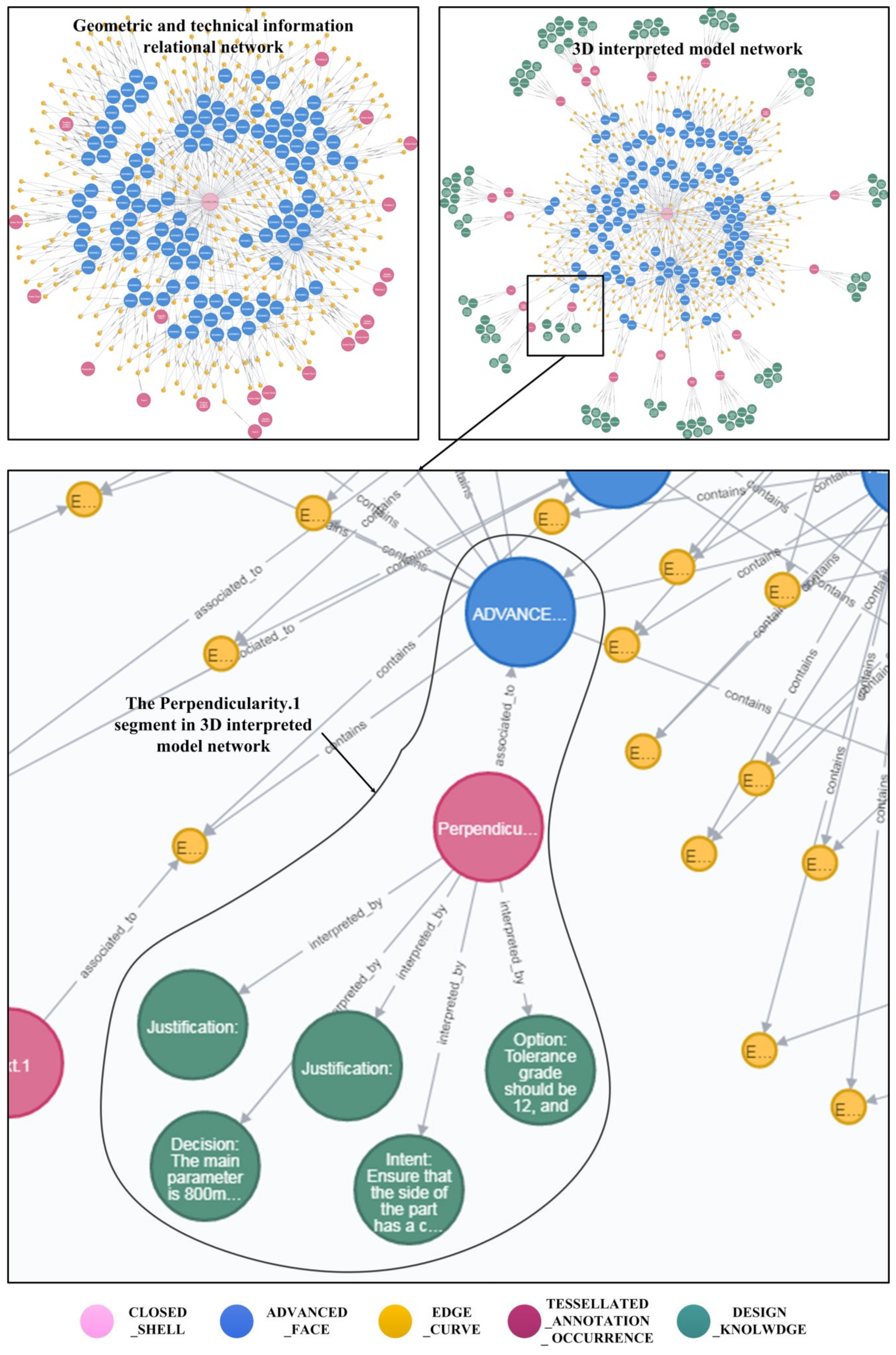
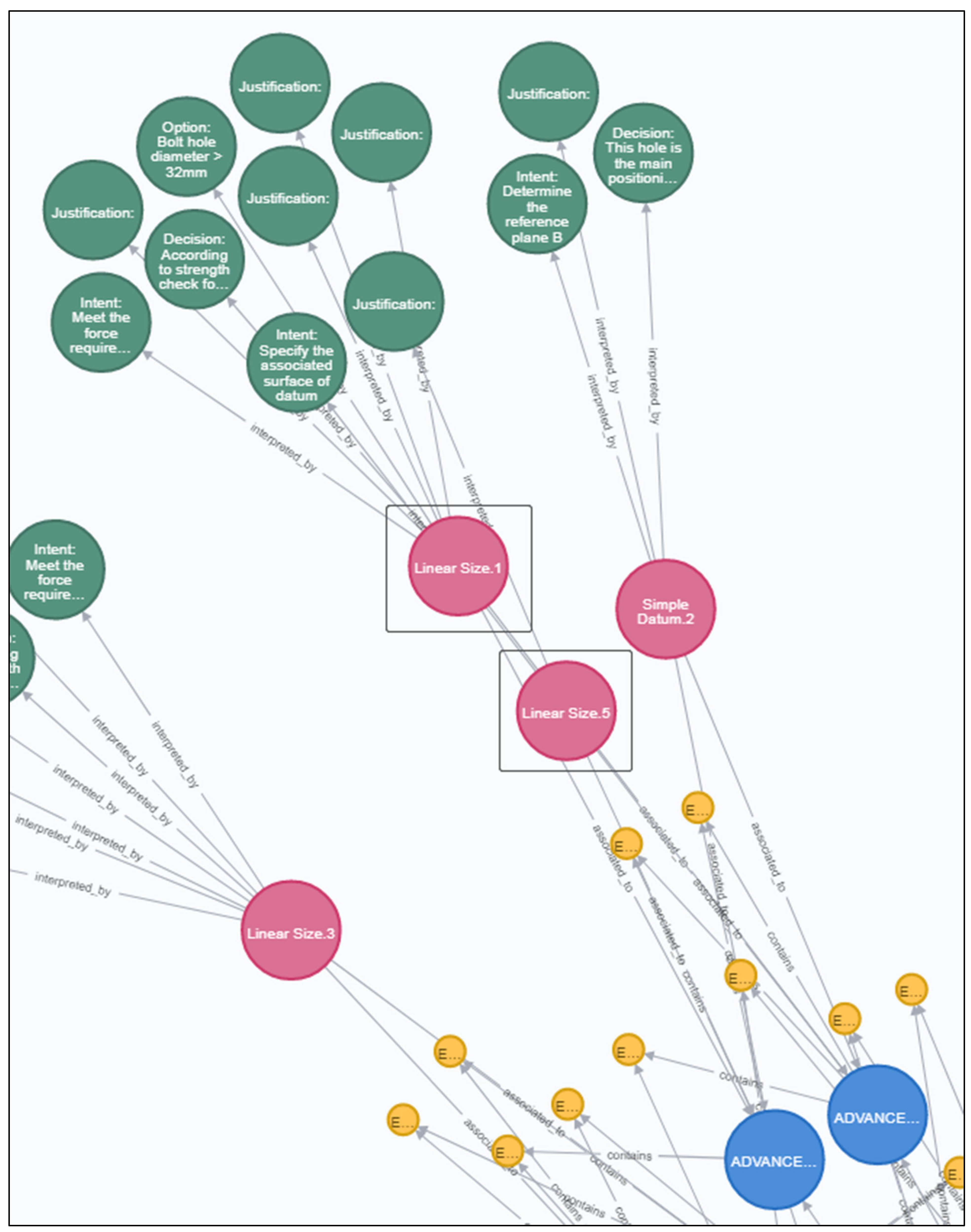
  • 3DIM has more extensive connotation and application scenarios. Compared with EAM, the annotation object of 3DIM model is not only limited to product geometric information, but also includes technical information. Moreover, the content of annotation knowledge is more extensive, including design intent, design justification, design decision and design option, which provides richer knowledge for the product model and comprehensively improves the quality of product model. At the same time, the granularity of knowledge annotation changes from feature level annotation to more fine-grained product information level annotation, which makes the object of design knowledge more specific. For example, when the process planning engineers find that the existing manufacturing methods are difficult to guarantee the Perpendicularity.1 in the model shown in Figure 12, they can easily view the designer’s design intent, design justification, design decision and design option through the method proposed in this paper, so as to understand the designer’s thinking and modify the tolerance within the range allowed by the design option. This kind of application is based on the fine-grained knowledge annotation of technical information, which is also the most significant difference between the knowledge annotation method proposed in this paper and that of EAM model.
  • The XML file structure is more reasonable. In the design knowledge annotation method of EAM, one XML file corresponds to multiple product models, and the annotation is taken as the basic structural unit. The knowledge annotation method of 3DIM model is one-to-one correspondence between XML file and product model, and the product information is taken as the basic structural unit, and each unit establishes a mapping relationship with the unique identifier of the product information. Compared with the two, the former is more suitable for the situation that the number of product models and annotations is less. When the number of models and annotations increases, it will bring problems such as the difficulty of maintaining the consistency between XML file and product models. So the method used in this paper is more suitable for practical application. On the one hand, through the establishment of the product model and its corresponding XML file association, it can be more convenient to realize the management of XML file. On the other hand, because an XML file contains only one product model knowledge annotation content, the maintenance of design knowledge is more convenient too.
  • The process of knowledge annotation is friendlier. In the aspect of knowledge annotation process automation, the proposed method sets the mechanism of XML file existence checking and initialization. The mechanism automatically checks the existence of the XML file. If the XML file does not exist, it automatically creates the file and initializes it. In the aspect of displaying design knowledge in 3D environment, the method proposed in this paper adopts two display strategies of design knowledge. The design knowledge associated with geometric information is displayed in the newly established annotation plane and led out by arrows. The design knowledge associated with the technical information is directly displayed in the annotation plane where the technical information is located. The two display strategies display the design knowledge in the model more reasonably, so as to intuitively distinguish the design knowledge corresponding to the geometric and technical information.

6.2. Availability of the 3D Interpreted Model Network Construction Method

It is very important for the further application to express 3DIM into a computer recognizable and processable 3D interpreted model network. One possible application is to solve the problem of propagation reasoning and assistant decision-making of product technical information change. In the relatively simple product model as shown in Figure 11, there are 21 pieces of technical information, and the distribution of technical information in 3D environment is relatively clear. However, when faced with complex product models, with the increase of technical information, the product models presented to designers are complicated. When designers change a certain size or technical information of the product, the product model is too complicated to accurately and intuitively find out the relevant technical information that will be affected. However, when 3DIM is represented as 3D interpreted model network, the product information that needs to be changed synchronously can be found by studying the corresponding information change propagation mechanism, and the corresponding design knowledge can be provided to support designers in making change decisions. For example, in Figure 14 (part of Figure 13), both Linear Size.1 and Linear Size.5 are associated with the same two surfaces. Therefore, when modifying Linear Size.1, we can find Linear Size.5 through the 3D interpreted model network according to the simple association mechanism, and push the Linear Size.5 and its corresponding design knowledge to the designers. Then the designers can confirm whether and how to change the value of Linear Size.5.
On the other hand, in the process of the 3D interpreted model network generation, the key to ensure the accuracy of 3D interpreted model network is how to extract and organize the geometric information, technical information and the relationship between them. This paper proposes an algorithm to extract information from STEP file to solve this problem. Through this algorithm, the geometric information, technical information and the relationship between them are extracted and stored in CSV file, and finally visualized in Neo4j.
This paper verifies the effectiveness of the algorithm by comparing the type and number of entities used to describe the geometric and technical information of the product before and after the implementation of the algorithm. The entity before extraction refers to the entity in the STEP file, which can be parsed by STEP File Analyzer tool [29]. This tool is a public access tool provided by NIST, which has the functions of STEP file parsing, STEP file analysis, consistency check and other functions. The entity extracted after the extraction refers to the entity recorded in the CSV file. In this example, the STEP file of the product model is parsed in STEP File Analyzer and compared with the data recorded in the CSV file, as shown in Table 3.
Through STEP File Analyzer, 85 entity types can be identified in STEP file. The number of TESSELLATED_ANNOTATION_OCCURRENCE, EDGE_CURVE, CLOSED_SHELL and ADVANCED_FACE is consistent with the number in CSV file, which indicates that the algorithm can extract such information accurately. At the same time, the STEP file also includes CARTESIAN_POINT, ORIENTED_EDGE, DIRECTIOND and other information with 81 types and 4315 entities. Although these entities reflect the geometric and topological relationship of product at some levels, it does not play a major role in the construction of 3D interpreted model network. Therefore, the proposed algorithm not only accurately extracts the relevant product information, but also effectively filters the redundant information in the STEP file.

6.3. Expected Impacts

As mentioned in the introduction, the main contribution of this paper is to propose a new product definition model, namely 3DIM. At the same time, on the basis of improving the existing design knowledge annotation method, the 3DIM is expressed as a 3D interpreted model network that can be recognized and processed by computer. The expected impacts of these contributions include:
  • In the research of product definition method, based on the MBD model and extended 3D annotation model, 3DIM integrates product geometric information, technical information and design knowledge that completely describes the product design process and forms a new product definition model. The 3DIM inherits and develops the way of product definition. The 3DIM is not only the carrier of product information, but also the carrier of design knowledge. It can not only transfer the product design results in the life cycle, but also transfer the design knowledge hidden behind the product information. In this case, the content of the product model is more comprehensive and enriched, and the quality of the model is better. Just as the annotation of software code can improve the readability and reusability of the program, the annotation of design knowledge can improve the understandability of product information and the reusability of product model. Therefore, 3DIM is essentially a new product definition method different from MBD model, which realizes the inheritance and development of product definition method;
  • In terms of industrial application, the construction method can guide enterprises to build 3DIM based on MBD model. The 3DIM can be applied to typical business activities such as design review, design learning and design manufacturing collaboration. The key problem of these business activities is the design communication of product, which is usually time-consuming and laborious, and needs repeated iteration, which increases the time and cost of product development. By integrating design intent, design justification, design decision and design option into the product model, other engineers can understand the product itself through the design knowledge in 3DIM and understand why the product is designed in this way. Therefore, some unnecessary design communication processes can be reduced or even removed, so as to change the situation of frequent meetings and discussions. The 3DIM is expressed as a 3D interpreted model network that can be recognized and processed by computer, which can be used to solve the design change decision-making problem of technical information in MBD model. As described in Section 6.2, when changing the product geometric information, the technical information that may need design change can be found through 3D interpreted model network and specific design change propagation mechanism. Then the technical information and its corresponding design knowledge can be transmitted to the designer and the designers can easily and quickly complete the design change of technical information according to these information and knowledge;
  • From the perspective of society, the application of 3DIM can save more social resources. The proposal and application of the MBD model can support the full 3D digital design and manufacturing, and replace the 2D drawings widely used in the traditional development mode. This paperless product development way saves social resources and makes the product development process greener and more economical. Similarly, because 3DIM integrates the product design process knowledge, it can also replace the design specification used to describe the product design process to achieve the same effect. In addition, the design communication and design review based on 3DIM can also save a lot of manpower, energy consumption and other resources compared with repeated meetings and discussions.

6.4. Limits and Future Developments

The main content of this paper is to put forward the concept of 3DIM, study the construction method of 3DIM and develop the corresponding 3D interpreted model construction tool. Although the method and tool achieve the goals of evolving the product definition model and improving the quality and capability of product model, there are still some limits:
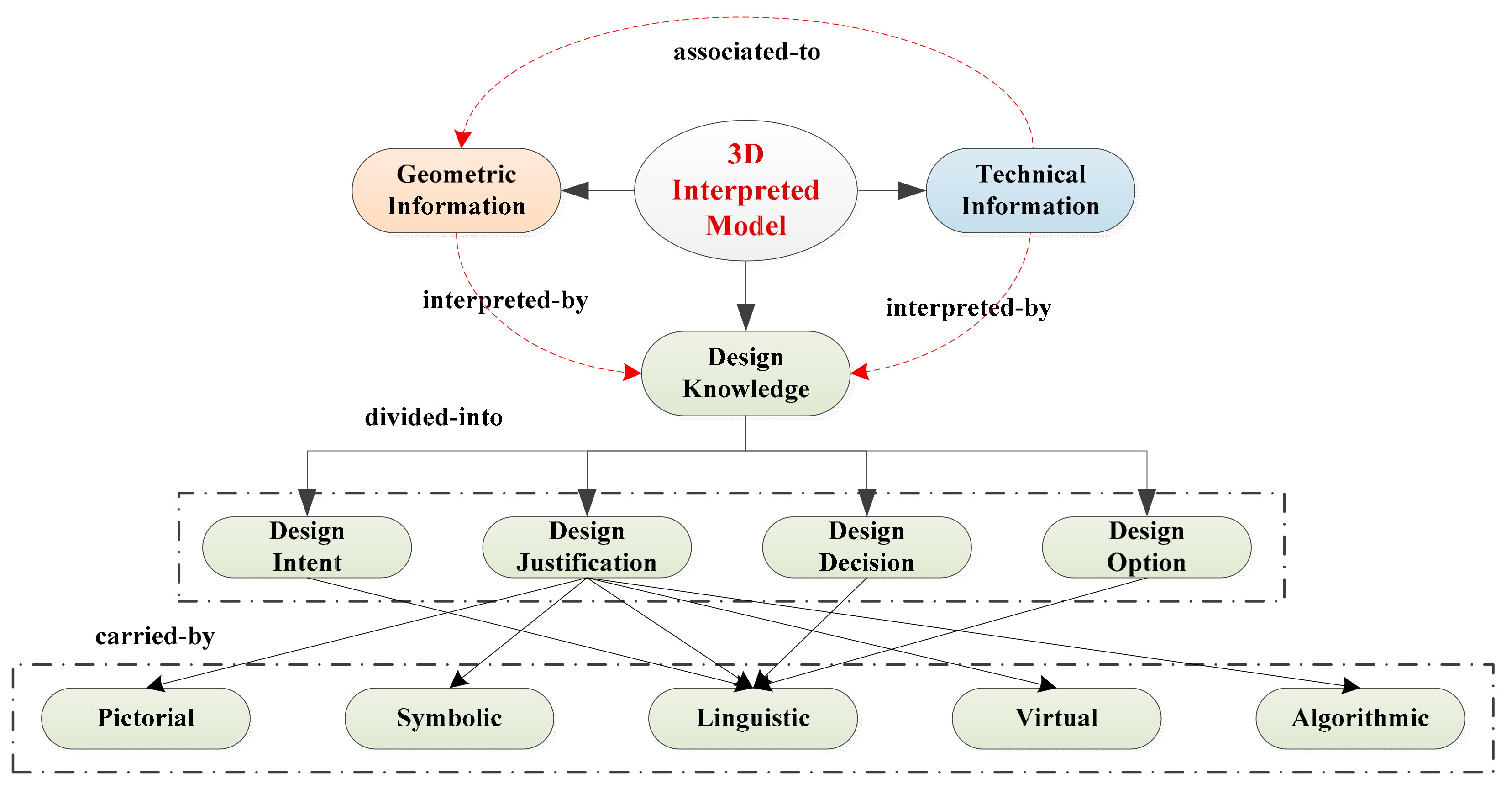
  • The proposed 3DIM integrates and fuses four types of design knowledge including design intent, design justification, design decision and design option, and supports design knowledge in different carrier forms such as pictorial, symbolic, linguistic, virtual and algorithmic. However, this division of design knowledge has certain universality. For different enterprises and products, the specific contents of design knowledge are different. For example, for consumer electronic products, the design intent mainly considers the needs of users, while for industrial equipment, the design intent needs to consider the functional performance indicators of products. Therefore, for different enterprises and products, the design knowledge division of 3DIM needs to be sorted out more finely to support the implementation of 3DIM;
  • The construction process of 3DIM includes design knowledge annotation and information extraction and knowledge fusion. The design knowledge annotation process mainly depends on the designer to select which knowledge to annotate. On the one hand, this process has a certain subjectivity, which affects the effect of knowledge annotation. On the other hand, the annotation process requires a certain amount of human and material resources and increases the workload of designer. To solve this problem, it is necessary to apply the idea of knowledge management to the process of design knowledge annotation, so as to provide some automation means such as design knowledge query, retrieval. Thus the time and cost caused by the process of design knowledge annotation can be reduced. In the aspect of information extraction and fusion algorithm, its main limitation is that the algorithm is only suitable for dealing with STEP as the neutral file format, but cannot deal with IGES, STL and other neutral file formats. To solve this problem, we need to analyze and compare the common neutral formats, research a more general information extraction and knowledge fusion algorithm, and adopt different strategies to adapt different types of neutral files in the specific implementation process, so as to make the application scope of the algorithm wider;
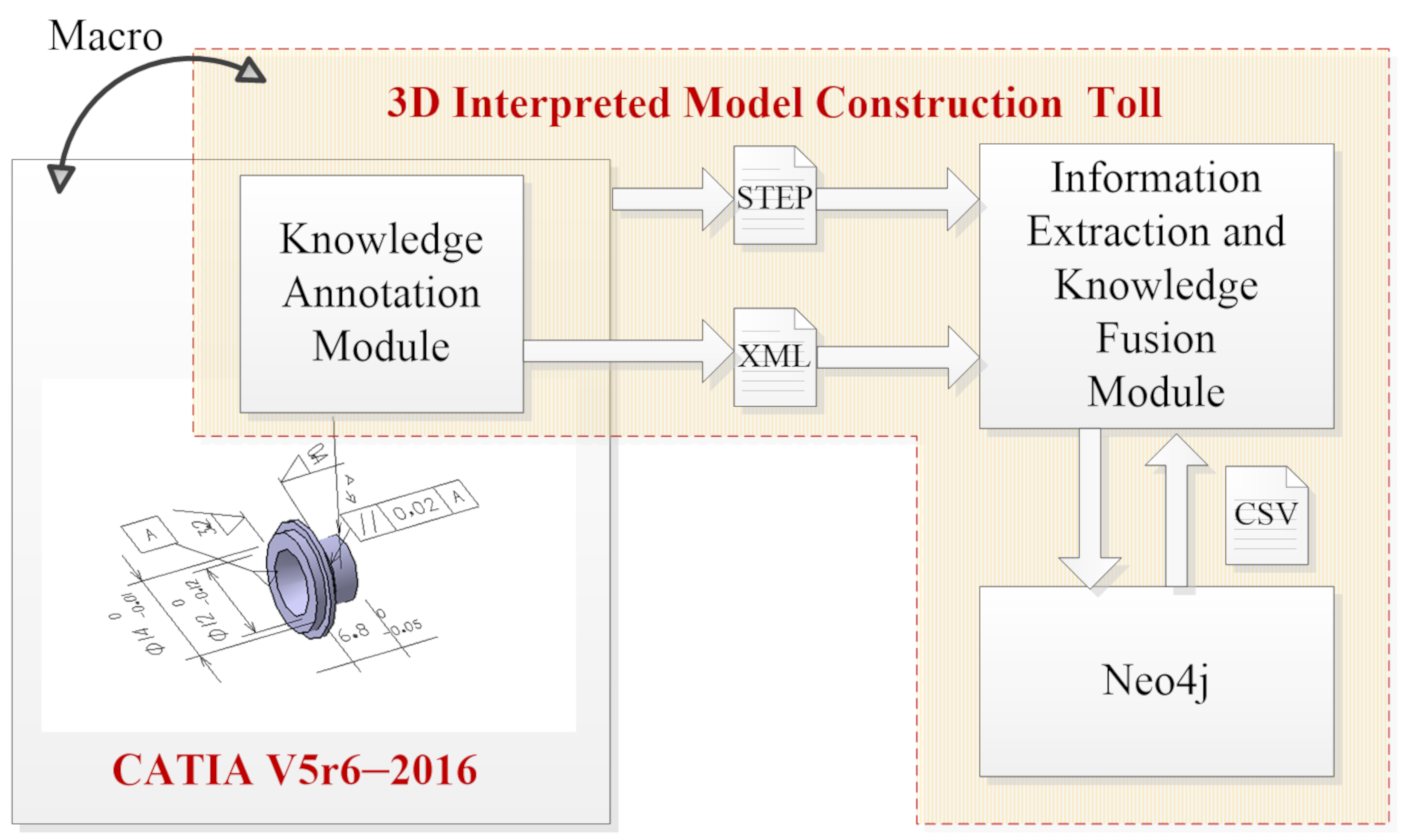
  • The 3D interpreted model construction tool developed in this paper is implemented based on the CATIA system, so it cannot be directly transplanted to UG NX, CREO and other CAD systems. In fact, the heterogeneous problem of CAD system is a very common and difficult. The best solution is to separate the design knowledge annotation module from the CAD system to form an independent tool. However, the independent tools need a lot of software development work to realize the basic functions such as CAD modeling and MBD annotation. For scientific research and engineering application, an acceptable method should be to develop corresponding 3D interpreted model construction tools for different CAD systems, which is also the main measure we plan to solve this problem.

7. Conclusions

Based on the 3D annotated model, a new product definition model named the 3D interpreted model is proposed in this paper. Its core idea is to integrate and fuse the 3D annotated model with design knowledge, so as to further improve the quality and application ability of the product model. First of all, the definition and representation of the 3D interpreted model are systematically elaborated, and the problem of what is the 3D interpreted model is solved. On this basis, the construction method of the 3D interpreted model is discussed. Through design knowledge annotation and information extraction and knowledge fusion, the construction of the 3D interpreted model is realized, and finally a computer recognizable and processable 3D interpreted model network is formed. Then, the 3D interpreted model and its construction process are demonstrated through a case study, and the proposed method is compared and verified from two aspects of design knowledge annotation, information extraction and knowledge fusion. The results show that as a new product definition model, the 3D interpreted model realizes the inheritance and development of product definition method, supports business activities and saves more social resources. The future work is to study a more general 3DIM construction method suited for different CAD systems and neutral formats and carry out further application based on the 3D interpreted model network.

Author Contributions

Conceptualization, J.L. and G.Y.; methodology, Y.H.; software, Y.H.; validation, Y.H., J.L. and G.Y.; formal analysis, Y.H.; investigation, Y.H.; resources, Y.H.; data curation, Y.H.; writing—original draft preparation, Y.H.; writing—review and editing, Y.H.; visualization, Y.H.; supervision, J.L.; project administration, G.Y.; funding acquisition, J.L. All authors have read and agreed to the published version of the manuscript.

Funding

This research was funded by the National Key Research and Development Program of China, grant number 2018YFB1701703.

Institutional Review Board Statement

Not applicable.

Informed Consent Statement

Not applicable.

Data Availability Statement

Publicly available datasets were analyzed in this study. This data can be found here: [https://www.nist.gov/el/systems-integration-division-73400/mbe-pmi-validation-and-conformance-testing-project] (accessed on 3 August 2021).

Conflicts of Interest

The authors declare no conflict of interest.

Appendix A

Input: 3DAM, design knowledge;
Output: 3DIM, knowledge index file;
Step 1: select product information item: select the product information to be annotated with design knowledge, including geometric information such as model, feature and surface, as well as technical information such as dimension, tolerance, roughness and datum. Then read the type and unique identifier of product information item;
Step 2: judge whether knowledge index file exists: if the knowledge index file already exists, jump to step 4, otherwise, execute step 3;
Step 3: initialize the knowledge index file: create the knowledge index file, and initialize the name, path, modification date and other basic information of the product model;
Step 4: fill in the design knowledge template: fill in the design knowledge template in the user interface, enter the text type knowledge, and associate the document resource type knowledge;
Step 5: display design knowledge in 3D environment: for geometric information, the annotation plane associated with the geometric information is established, and the design knowledge is displayed in the newly established annotation plane. For technical information, the design knowledge is directly displayed in the annotation plane of the technical information;
Step 6: update the knowledge index file: update the design knowledge and the corresponding product information in the design knowledge template to the knowledge index file;
Step 7: judge whether the construction of 3DIM is completed: if the construction is not finished, go to step 1 and select other product information to continue knowledge annotation.

References

  1. Singh, V.; Willcox, K.E. Engineering Design with Digital Thread. AIAA J. 2018, 56, 4515–4528. [Google Scholar] [CrossRef]
  2. Lubell, J.; Chen, K.; Horst, J. Model Based Enterprise/Technical Data Package Summit Report; National Institute of Standards and Technology: Gaithersburg, MD, USA, 2012. [Google Scholar]
  3. Geng, J.; Tian, X.; Bai, M. A Design Method for Three-Dimensional Maintenance, Repair and Overhaul Job Card of Complex Products. Comput. Ind. 2014, 65, 200–209. [Google Scholar] [CrossRef]
  4. Hedberg, T.; Lubell, J.; Fischer, L. Testing the Digital Thread in Support of Model-Based Manufacturing and Inspection. J. Comput. Inf. Sci. Eng. 2016, 16, 021001.1–021001.10. [Google Scholar] [CrossRef] [PubMed] [Green Version]
  5. Quintana, V.; Rivest, L.; Pellerin, R. Will Model-Based Definition Replace Engineering Drawings Throughout the Product Lifecycle? A Global Perspective from Aero-Space Industry. Comput. Ind. 2010, 61, 497–508. [Google Scholar] [CrossRef]
  6. Camba, J.; Contero, M.; Johnson, M. Extended 3D Annotations as a New Mechanism to Explicitly Communicate Geometric Design Intent and Increase CAD Model Reusability. Comput. Aided Des. 2014, 57, 61–73. [Google Scholar] [CrossRef] [Green Version]
  7. Lundin, M.; Sandberg, S.; Mats, N. Knowledge Retention and Reuse: Using CAD Models as Carriers of Knowledge in Product Development. Int. Des. Eng. Tech. Conf. Comput. Inf. Eng. Conf. 2010, 44113, 1173–1182. [Google Scholar]
  8. MBE PMI Validation and Conformance Testing Project. Available online: https://www.nist.gov/el/systems-integration-division-73400/mbe-pmi-validation-and-conformance-testing-project (accessed on 15 April 2021).
  9. Camba, J.D.; Contero, M.; Company, P. On the Integration of Model-Based Feature Information in Product Lifecycle Management Systems. Int. J. Inf. Manag. 2017, 37, 611–621. [Google Scholar] [CrossRef] [Green Version]
  10. Patel, M.; Ball, A.; Ding, L. Strategies for the Curation of CAD Engineering Models. Int. J. Digit. Curation 2009, 4, 84–97. [Google Scholar] [CrossRef] [Green Version]
  11. ASME Y14.41 Digital Product Definition Data Practices; The American Society of Mechanical Engineers: New York, NY, USA, 2003.
  12. ISO 16792 Technical Product Documentation-Digital Product Definition Data Practices; International Organization for Standardization: Geneva, Switzerland, 2006.
  13. Ruemler, S.P.; Zimmerman, K.E.; Hartman, N.W. Promoting Model-Based Definition to Establish a Complete Product Definition. J. Manuf. Sci. Eng. 2016, 139, 051008. [Google Scholar] [CrossRef] [PubMed] [Green Version]
  14. Huang, R.; Zhang, S.; Bai, X. Multi-Level Structuralized Model-Based Definition Model Based on Machining Features for Manufacturing Reuse of Mechanical Parts. Int. J. Adv. Manuf. Technol. 2014, 75, 1035–1048. [Google Scholar] [CrossRef]
  15. ASME Y14.5 Dimensioning and Tolerancing; The American Society of Mechanical Engineers: New York, NY, USA, 2003.
  16. ISO 1101 Geometrical Product Specifications (GPS)-Geometrical Tolerancing-Tolerances of Form, Orientation, Location, and Run-Out; International Organization for Standardization: Geneva, Switzerland, 2012.
  17. ISO 10303–242 Industrial Automation Systems and Integration-Product Data Representation and Exchange-Part 242: Application Protocol: Managed Model-Based 3D Engineering; International Organization for Standardization: Geneva, Switzerland, 2014.
  18. Lipman, R.; Lubell, J. Conformance Checking of PMI Representation in CAD Model STEP Data Exchange Files. Comput. Aided Des. 2015, 66, 14–23. [Google Scholar] [CrossRef]
  19. Hallmann, M.; Goetz, S.; Schleich, B. Mapping of GD&T Information and PMI Between 3D Product Models in the STEP and STL Format. Comput. Aided Des. 2019, 115, 293–306. [Google Scholar]
  20. Barbau, R.; Krima, S.; Rachuri, S. OntoSTEP: Enriching Product Model Data Using Ontologies. Comput. Aided Des. 2012, 44, 575–590. [Google Scholar] [CrossRef]
  21. AP 242 Edition 1. Available online: http://www.ap242.org/ap242ed1 (accessed on 27 July 2021).
  22. Chen, W.L.; Xie, S.Q.; Zeng, F.F. A New Process Knowledge Representation Approach Using Parameter Flow Chart. Comput. Ind. 2011, 62, 9–22. [Google Scholar] [CrossRef]
  23. Kim, K.Y.; Kim, Y.S. Causal Design Knowledge: Alternative Representation Method for Product Development Knowledge Management. Comput. Aided Des. 2011, 43, 1137–1153. [Google Scholar] [CrossRef]
  24. Chandrasegaran, S.K.; Ramani, K.; Sriram, R.D. The Evolution, Challenges, and Future of Knowledge Representation in Product Design Systems. Comput. Aided Des. 2013, 45, 204–228. [Google Scholar] [CrossRef]
  25. Poorkiany, M.; Johansson, J.; Elgh, F. Capturing, Structuring and Accessing Design Rationale in Integrated Product Design and Manufacturing Processes. Adv. Eng. Inform. 2016, 30, 522–536. [Google Scholar] [CrossRef] [Green Version]
  26. Kunz, W.; Rittel, H.W.J. Issue as Elements of Information Systems. University of California: Berkeley, CA, USA, 1970. [Google Scholar]
  27. Liu, Y.; Liang, Y.; Kwong, C.K. A New Design Rationale Representation Model for Rationale Mining. J. Comput. Inf. Sci. Eng. 2010, 10, 90–99. [Google Scholar] [CrossRef]
  28. Liu, J.H.; Hu, X.J. A Reuse Oriented Representation Model for Capturing and Formalizing the Evolving Design Rationale. Artif. Intell. Eng. Des. Anal. Manuf. 2013, 27, 401–413. [Google Scholar] [CrossRef]
  29. STEP File Analyzer and Viewer. Available online: https://www.nist.gov/services-resources/software/step-file-analyzer-and-viewer (accessed on 15 April 2021).
Figure 1. The content of MBD dataset specified in ASME Y14.41.
Applsci 11 07192 g001
Figure 2. The content of MBD model specified in ASME Y14.41.
Applsci 11 07192 g002
Figure 3. The developing process of the product model from a 3D geometric model to a 3D interpreted model.
Applsci 11 07192 g003
Figure 4. The differences of related models from the perspective of product model content.
Applsci 11 07192 g004
Figure 5. The representation structure of 3DIM.
Applsci 11 07192 g005
Figure 6. The overall construction process of the 3D interpreted model network.
Applsci 11 07192 g006
Figure 7. The process of design knowledge annotation.
Applsci 11 07192 g007
Figure 9. The algorithm of information extraction and knowledge fusion.
Applsci 11 07192 g009
Figure 10. The system architecture of 3D interpreted model construction tool.
Applsci 11 07192 g010
Figure 11. The design knowledge annotation interface.
Applsci 11 07192 g011
Figure 12. The 3DIM and the corresponding knowledge index file.
Applsci 11 07192 g012
Figure 13. The 3D interpreted model network.
Applsci 11 07192 g013
Figure 14. Application case of 3D interpreted model network.
Applsci 11 07192 g014
Table 1. Design Knowledge in 3DIM.
Knowledge TypeMeaning and Examples
Design intentDesign intent is used to describe the purpose, goal or reason of geometric information and technical information in 3DIM, including the function, behavior and structure of geometric information and technical information.
Design justificationDesign justification is the professional knowledge that designers need to realize design intent, including design references, design experience, design standard, etc.
Design decisionDesign decision is used to describe the process in which designers form design options according to design justification and finally define the final results of product geometric and technical information
Design optionDesign option is used to describe the design space of geometric and technical information in 3DIM, including optional design scheme, value range, etc.
Table 2. The comparison of design knowledge annotation method.
TypeComparison PointEAM3DIM
Overall comparisonObject of knowledge annotationGeometric informationGeometric and technical information
Content of knowledge annotationGeometric design intentDesign intent (including geometric design intent and technical design intent), design justification, design decision and design option
The existing form of design knowledgeTextualPictorial, Symbolic, Linguistic, Virtual and Algorithmic
Uniqueness of annotated objectsFeature nameUnique identifier of the product information
Granularity of knowledge annotationFeature level annotationProduct information level annotation
Comparison of XML file structureCorrespondence between XML file and product modelOne XML file corresponds to multiple product modelsOne XML file corresponds to one product model
Basic structure unit of XML fileTaking annotation as basic structural unitTaking product information as basic structural unit
Comparison of annotation processExistence checking and initialization of XML fileNot mentionedAutomatically check the existence of the XML file, if not, create the file and initialize it
The display way of design knowledgeDesign knowledge is displayed in the newly created annotation plane in the form of association groupThe design knowledge for geometric information is displayed in the newly established annotation plane; The design knowledge for technical information is directly displayed in the annotation plane where the technical information is located
Table 3. Comparison of entities before and after the extraction algorithm.
File nameEntities TypeCLOSED_
SHELL
AVANCED_
FACE
EDGE_
CURVE
TESSELLATED_ANNOTATION_
OCCURRENCE
Others
STEP File Analyzer851117318214315
CSV Files51117318210
Publisher’s Note: MDPI stays neutral with regard to jurisdictional claims in published maps and institutional affiliations.

