Abstract
This paper aims to study the mechanical and electrical properties of the composite structure of PVC film and film cell under biaxial tension. The saddle PVC membrane structure with thin-film battery was obtained by biaxial tensile tests carried out on the composite structure along the fiber direction and at an angle of 45 degrees to the fiber, respectively. The deformation of the film cell and PVC membrane materials was tested using digital image technology, and the voltage of the film cell was tested using a multimeter. The results showed that the tensile strain occurred in both membrane batteries and PVC membrane at different loading levels, and the former was always less than the latter. At a tensile load with the ultimate load ratio of 60%, it was only at the film cell’s outer edge that the stripping occurred. Under the illumination of a stable light source, the film cell voltage decreased gradually with the increasing tensile load. No more than 10% of the cell voltage drop occurred when the membrane material, the principal tensile strain of the cell, and the cell’s expansion area ratio were less than 3.1%, 2.8%, and 1.03, respectively. The experimental results show that the film cell can be applied to the saddle membrane structure by controlling the appropriate load.
1. Introduction
Polyvinyl chloride (PVC) was widely used in many industries, such as PVC film used in the construction industry. Tension membrane structure composed of PVC, compared with the traditional structure, has the advantages of a lightweight, large span, accessibility, rich architectural modelling, convenient construction, economy, transparency, and so on [1,2]. Therefore, it has been widely used in various long-span buildings [3,4]. In practical application, not all membrane structures are flat planes. For example, the saddle-shaped tensile membrane structure is a typical stretch PVC membrane structure, which as a basic unit can be used in small span architectural works. The different forms of membrane structure buildings can be obtained through expansion and combination methods for the full use of PVC film in the building. Because PVC membrane materials are generally organic materials, these materials are often exposed to the sun, and they easily age and deteriorate, affecting the service life of the tension-membrane structure [5,6]. The thin-Film Battery is attached to the surface of the PVC tension membrane to form a composite structure, which can prevent the damage of the UV to the tension membrane. Moreover, compared with the traditional method of coating the protective layer on the PVC tension film, the composite structure can convert the light energy into electrical energy, which is conducive to improving energy utilization. The composite structure can be a solution to improve the sustainability of PVC tension film, especially for remote islands and mountainous areas and areas with inconvenient power supplies. As the most powerful technology in solar energy utilization, solar photovoltaic power generation technology has become the hot spot of research and application worldwide [7,8]. At present, crystalline silicon photovoltaic cells are still the main products of photovoltaic cells [9,10]. Compared with crystalline silicon solar cells, amorphous silicon thin-film solar cells have lower conversion efficiency [11]. At present, due to efficiency, cost, stability and other reasons, the global market share of amorphous silicon thin-film solar cells is far lower than that of crystalline silicon thin-film solar cells [12]. However, in recent years, some researchers [13,14] have tried to improve the conversion efficiency of amorphous silicon photovoltaic cells and have achieved some results. Although the improvement of conversion efficiency is not significant, some researchers still keep trying. Some progress has also been made in studying organic materials used in solar cells [15,16,17]. In addition, amorphous silicon thin-film solar cells are highly bendable [18] and can be manufactured into many sizes and shapes [19]. Based on this, some researchers [20,21] tried to combine amorphous silicon solar cells with building substrates or fibre-reinforced polymer panels to study the performance of their composite structure and explored lower the installation costs. Therefore, amorphous silicon thin-film photovoltaic cells can be considered one of the potential options for building integrated photovoltaic (BIPV), which is also in line with the current building energy efficiency policy.
In recent years, some scholars have explored the combination of membrane structure and thin-film battery. For example, Xu [22] conducted an experimental study on the composite film’s mechanical and power generation performance of flexible film solar cell and PVDF film. The results showed that the composite film’s tensile strength was between 29.8 MPa and 32.4 MPa under different tensile directions. The composite film’s output voltage decreased when it was stretched perpendicular to the direction of the cell. Yin [23] studied the electrical, thermal, and mechanical properties of the composite materials of flexible thin-film solar cells and ethylene tetrafluoroethylene thin film. The results show that the yield stress and elastic modulus of flexible thin-film solar cells on the ETFE substrate were 20.2 MPa and 1110 MPa. The open-circuit voltage has an obvious abrupt drop point. The specimen’s failure is due to the membrane rupture for the double-layer ETFE coated single flexible thin-film solar cell specimen. Compared with the previous example, the interaction between this specimen’s electrical, thermal, and mechanical properties is more significant. Zhang [24] studied the mechanical and electrical properties of flexible amorphous silicon solar cells and PVC films using numerical models. The results show that the composite’s mechanical and electrical properties were affected by the composite and tensile direction. The failure modes of specimens were quite different after stretching in different directions. The above research methods were uniaxial tensile tests on the membrane materials. After compounding the flexible membrane cell with membrane structure, Scotta [25] carried out a uniaxial tensile test and biaxial tensile test. The results show that the thin-film battery can deform and stretch usually when the membrane material deforms without affecting the power generation performance. In this kind of biaxial tensile test, all loads’ directions were in the same plane, which was suitable for the inflatable membrane. However, for saddle membrane structure, all membrane materials form a three-dimensional surface. Even if the same load is applied, the saddle-shaped film material’s stress state is different from that of the same flat membrane material. Therefore, developing new test methods to test the saddle membrane structure’s deformation and power generation performance is necessary.
The traditional sticking strain gauge method may be inconvenient to test the battery and membrane’s deformation because of its stiffness. Digital image correlation (DIC) technology [26,27] is based on the grey level of a speckle image. Through a series of calculations of the pixel value, the displacement and deformation of each pixel position will be obtained, and the deformation cloud image will be formed. In this study, an amorphous silicon flexible thin-film battery was attached to the PVC membrane. A new loading device was designed to load the PVC membrane. By adjusting the support’s height, the biaxial tension was not in the same plane, and the composite structure of the saddle-shaped membrane and thin-film battery was obtained. A tungsten halide lamp was used to irradiate the light film battery. The relationship between the deformation of the film and the change of voltage was obtained by DIC technology.
2. Experimental Materials and Test Methods
In this study, PVC membrane material was produced by Shanghai Yeli Membrane Structure Co., Ltd. ( Shanghai, China) with the size of 1060 × 1060 × 0.5 mm. According to China National Standard (GB13022-91), the uniaxial tension mechanical properties of PVC film were obtained, including two categories along the 0-degree direction and 45-degree angle direction of the membrane fiber. Three groups of experiments were carried out for each type. The films were stretched using a model LANDMARK tension and torsion tester manufactured by MTS Corporation of America. The loading method was used as displacement control. The loading speed was 10 mm/min. The test procedure is shown in Figure 1.
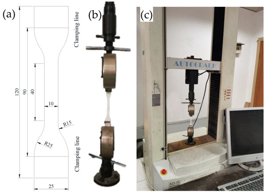
Figure 1.
Uniaxial tension test process: (a) uniaxial tension sample size/mm, (b) clamping of specimens, and (c) test machine loading.
Thin-film batteries (size: 178 × 40 × 0.5 mm; model: amorphous silicon thin-film solar cells on a 0.5 WCel flexible substrate; manufacturer: United-Solar (Michigan, USA), were combined with PVC membranes to form a composite structure, as shown in Figure 2. The technical specifications of thin-film batteries are shown in Table 1. Film batteries were firmly adhered to the center and corner of the PVC membranes using alpha-cyanoacrylate glue so that no relative slip between the membrane batteries and the PVC membranes occurs during tension. Because PVC membranes and thin-film batteries are orthotropic materials, two types of bidirectional loading were designed. One was loaded along the polyester fiber base fabric direction, which corresponds to Battery A and Battery B. Another way is to load at an angle of 45 degrees between the fibers, which corresponds to battery C and D. Three groups of tests were carried out for each loading mode, with six specimens. To prevent edge tearing, edges were treated according to the China Membrane Structure Technical Regulation (CECS158-2015). That is, the boundary of the PVC membrane was folded and thermally combined to form a 60 mm perimeter sheath. Then, the 5 mm diameter side rope was passed through the sheath and around the PVC membrane’s edge. At the corner of the PVC membrane, the specimens were clamped by an arc plate.
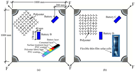
Figure 2.
Diagram of the composite structure of film battery and PVC membrane: (a) loading along the fiber direction, (b) loading at an angle of 45 degrees to the fiber.

Table 1.
Technical parameter for thin-film batteries.
A biaxial diagonal tension loading device with variable height difference was designed. With this device, the tension force was not in the same plane, so that the tension film forms a saddle-shaped surface. The schematic diagram of the device is shown in Figure 3. The oil pump and two-way oil cylinder were used to exert tension. In order to ensure high accuracy, the oil pump and two-way oil cylinder are calibrated according to China’s Verification Specification for Hydraulic Jacks (JJG621-2012). The supporting steel pipes with a pulley were used to adjust the tension position and direction. The supportive steel pipe’s outer and inner diameter is 78 mm and 74 mm, respectively. The length of that is 1200 mm. There was a pin inside the steel pipe, and the plug is a solid steel bar with a diameter of 11 mm. The steel pipe was inserted into the reaction bearing platform’s hole, and the tension position was adjusted by adjusting the extension length of the steel pipe. The four steel pipes’ diagonal size was 3905 mm, and the height difference of the adjacent steel pipes was 100 mm.
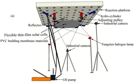
Figure 3.
The biaxial loading device of composite structure: (a) three-dimensional schematic diagram of the device, (b) overall test process, (c) pipe and pulley support, (d) connection between steel plate clamp and membrane material, and (e) voltage test device.
Before tensioning the PVC membrane, the wire rope was bypassed by the adjustment wheel at the end of the supporting steel tube, and the steel splint of the PVC membrane was connected with the hydraulic cylinder under tension by the wire rope. Support reactions were provided for steel pipes and hydraulic cylinders using platforms in the structure laboratory. The loading device was a hydraulic loading system consisting of two double-eared cylinders and a hydraulic oil pump. The shunt valve was used to make the two cylinders have the same oil pressure to achieve the synchronous loading and unloading of PVC membranes. The pull sensor was used to calibrate the pull force generated by the hydraulic cylinder before loading. Then, the PVC membranes were stretched at a loading speed of 5 kN/min until they were destroyed.
Two 1000 W standard tungsten halogen lamps were irradiated on the surface of thin-film batteries, as shown in Figure 3. The halogen tungsten lamps were turned on only during loading to reduce the effect of temperature on PVC membranes. The multimeters (measuring range: 2 V; accuracy: 0.5% + 1) were used to measure the potential of thin-film batteries. The camcorder was used to record the change of the multimeter value during loading, and the voltage test is shown in Figure 3e.
Digital image correlation technology (DIC) has good accuracy and the ability to monitor real-time full-field displacement, so it is widely used to study surface strain field or crack behavior [28,29]. DIC was used to obtain the strain cloud image on the surface of the thin-film battery. Because the film battery is much smaller than the entire PVC film, even if the film is a saddle-shaped structure, the surface of the film cell can still be regarded as a plane.
The speckles were sprayed on three areas of the membrane cell surface with 13 × 13 mm area and on the PVC membrane at the exact location as the cell, as shown in Figure 4.
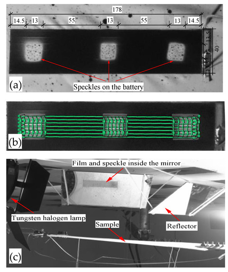
Figure 4.
Speckle position and expansion deformation data: (a) thin film battery and the speckles on it (unit: mm), (b) data extraction of thin-film battery deformation, (c) film battery image and speckle inside the mirror.
To establish the relationship between cell deformation and voltage, the average strain under different tensile loads, i.e., the length variation of the green line in Figure 4b, was obtained along with the longitudinal and transverse directions of the thin-film cell. The thin-film cell area change can be calculated from the length change of the green line. For speckle areas on batteries, the expansion area is defined as (area after deformationarea before deformation)/area before deformation. As a result, the relationship between the thin film battery’s voltage and its expansion area can be obtained.
Industrial cameras (Model: 14 megapixels, JHSM1400; Manufacturer: Shenzhen Jinghang Technology Co., Ltd., Shenzhen, China) were set on both sides of the PVC film. The first industrial camera was filmed perpendicular to the battery surface. Due to space location limitations, based on the mirror reflection principle, a plane mirror was placed at the 45-degree angle of PVC film. Then, another industrial camera was used to take pictures of the PVC film inside the reflector, as shown in Figure 4c. During the loading process, the industrial camera was set to take pictures every second. Strain clouds at speckle locations at different loading stages were calculated by using DIC [30,31].
3. Results and Analysis
3.1. Basic Mechanical Properties of PVC Membrane
The basic uniaxial tensile properties of PVC membranes are shown in Figure 5. Since the differences among the three groups of test results are very small, and the errors are all within 5%, we show a group of data that is closest to the mean. It can be seen from the figure that, with the increase of strain, the stress of the membrane stretched along with the fiber direction increases faster than that stretched along the 45-degree angle of the fiber. The former breaks at a strain of 40%, while the latter breaks at a strain 2.5 times higher than the former. The former has a tensile strength of 67.3MPa, while the latter has only 0.55 times the former, i.e., 37 MPa.
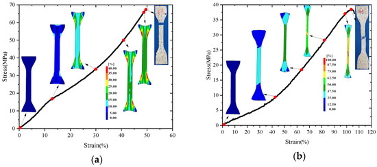
Figure 5.
Experimental results of PVC membrane under uniaxial tension: (a) fiber direction tension, (b) tensile force 45 degrees from fiber direction.
It can be seen from the strain cloud and failure pattern of uniaxial tension PVC membrane during the loading process that the strain of PVC membrane changes with the increase of load level. For stretching along the fiber direction, the fibers in the PVC membrane are all broken simultaneously, which indicates that the PVC membrane is a brittle fracture. For stretching along with the 45-degree inclination of the fiber, the film’s rupture cut is 45 degrees inclined to the stretching direction. Some of the fibers were pulled out and broken, indicating shear failure.
For specimens stretched along the fiber direction, the strain cloud pattern is more uniform. Excessive local strain only occurs in the end clamping area. It indicates that the fibers at the cross-section of this sample all bear a high tensile force. For specimens stretched at an angle of 45 degrees along with the fiber, the strain inside the specimens varies unevenly. It indicates a relative slip between the fibers in the membrane, and they were under the combined stress of shear and tension. This loading method results in low tensile strength and high strain of PVC membranes. The above two samples’ strain distributions will further affect the deformation properties of the attached thin-film cells.
3.2. Deformation of Membrane and Battery
Through the experiment in Figure 3, the corresponding limit loads in Figure 2a,b were 10.52 and 14.61 kN, respectively. The ratio of actual load to ultimate load is defined as the load level. The PVC membrane material at the thin-film battery B and the thin-film battery in Figure 2 is selected for analysis. Strain clouds at different load levels are shown in Figure 6. The general trend of strain clouds for the remaining batteries is similar and will not be repeated here.
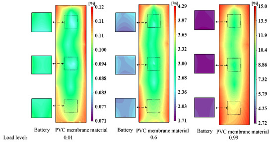
Figure 6.
Strain cloud maps of thin-film cells and PVC films at different load levels.
It can be seen from the figure that the principal tensile strain of the thin-film battery and the principal tensile strain of the PVC film at the same position show non-uniform distribution at different load levels. The principal tensile strain around the PVC membrane is significantly larger than that inside the membrane cell. Through actual observation, it was found that the edge of the film cell and the PVC membrane had slightly peeled off when the PVC membrane was about to be destroyed. This phenomenon explains that thin-film batteries adhere to the PVC membrane material, which results in a joint force between the two. The stiffness of the former was more significant than that of the latter. There was a bond slip between the two at the edge of the thin-film cell. This results in less stress on the membrane cell but more stress on the PVC membrane, which causes a much higher strain on the PVC membrane at the edge.
The strain data at each pixel in Figure 6 were extracted, and the mean values of principal tensile strains were calculated, and so on. The relationship between load level and the mean value of principal tensile strain is shown in Figure 7.
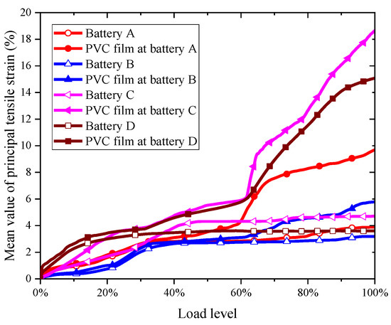
Figure 7.
Relation between principal tensile strain and load level.
It can be seen from the diagram that the principal tensile strain of all thin-film batteries and PVC membranes increases with increasing load levels. When the load level is less than 0.3, the thin-film battery’s principal tensile strain increases rapidly with the load level increase. Meanwhile, when the load level is more significant than 0.3, they increase again slowly. When the load level is less than 0.6, the strain of PVC film increases slowly. While when the load level is higher than 0.6, the strain of the PVC membrane increases rapidly. When the load level is 0.6, the strain of the PVC membrane at positions A and B of the film cell is about 3%, and at positions C and D of the film cell is about 6%. Simultaneously, only at the edge of the thin film cell, the phenomenon of separating from the PVC film material began to appear. In practical engineering, to ensure that the membrane battery does not disengage from the membrane material during service, the applied load level should be less than 0.6, or the principal tensile strain of the PVC membrane material at the membrane battery should be less than 3%. The saddle-shaped PVC membrane was in a complex stress state in space and usually broke at the four corners first. The strain of the PVC membrane at the membrane cell location was significantly less than that under uniaxial tension. The principal tensile strain of all thin-film batteries shows a similar trend. However, the principal tensile strains of the PVC film at the positions of the thin-film cell C and D are significantly greater than that of the rest. This is because ropes surrounded the saddle-shaped PVC membrane. Compared with the PVC membrane adhering to film batteries A and B, the fibers in the PVC membrane adhering to film batteries C and D were in a more constant tension state and the ultimate strength obtained by experiments was much higher. Therefore, the principal tensile strain of the PVC film at the thin-film batteries C and D was also much more significant at the same load level. Simultaneously, the membrane cell’s principal tensile strain is always smaller than that of the PVC membrane.
3.3. Voltage Change Caused by Load
To analyze the effect of loads on the deformation and output voltage of thin-film batteries, the thin-film cell area ratio can be obtained by dividing the deformed area by the area before loading. The relative initial voltage can be obtained by dividing the thin-film battery’s voltage at different load levels by the thin-film battery’s initial voltage. The results of the three tests for each load combination were counted, and their mean values were calculated. All the relative errors between the experimental values and the mean values were less than 5%. Figure 8 shows the statistical results of the expansion area ratio and relative voltage of the thin film cell (C and D) under different load levels. The same method was used for the statistics of thin-film cells A and B. Therefore, the average values of the three groups of the test results were used for the following analysis, as shown in Figure 9.
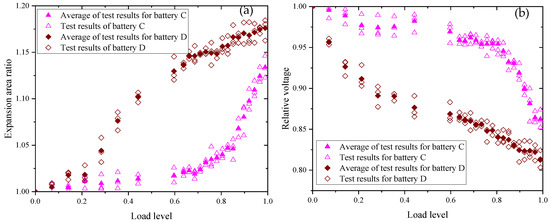
Figure 8.
Effect of load level on battery deformation and voltage: (a) expansion area ratio, and (b) relative voltage.
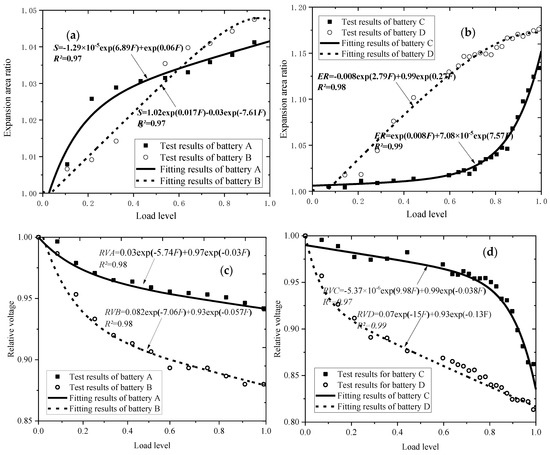
Figure 9.
Relationship between expansion area ratio and relative voltage of thin-film cells and load level: (a,b) are expansion area ratio; (c,d) are relative voltage.
Figure 9a,c shows that when loaded along the fiber direction, the expansion area ratio of film batteries A and B increases, and their output voltage decreases as the load increases. They change faster first and then slower. Curve fitting shows that their variation law is close to exponential form. The output voltage of thin-film battery A slowly decreases while B decreases faster. Before loading, the initial voltage of battery A was 1.582 V, and when the membrane structure was damaged, the voltage was 1.489 V, which decreased by 5.88%. The initial voltage of battery B before loading was 1.556 V, while the voltage at the breakdown was 1.366 V, which decreases by 12.21%. The output voltage of battery B decays more severely than that of battery A. Battery B is located in the center of the PVC membrane, where the fibers were subjected to symmetrical bi-directional tensile loads. However, the membrane fibers at location A of the battery are subjected to asymmetric loads. The membrane fiber at location A of the battery is more sensitive to load. Figure 9b,d shows that the deformation and voltage variation of thin-film batteries B and D with load levels are similar to those of A and C. However, the voltage of battery C decreases slowly first and then rapidly when the load level is more significant than 0.6. This is consistent with the variation rule of its expansion area. The initial voltage at cell C was 1.568 V, and the output voltage was 1.348 V when the membrane structure is damaged, which decreases by 14.03%. The thin-film battery D’s initial voltage was 1.515 V, while the voltage at the breakdown was 1.202 V, which decreased by 20.67%. Initial voltages vary for different batteries because thin-film batteries’ voltages were affected by factors such as cell differences and light intensity.
The parameters corresponding to the critical point of battery voltage failure can be obtained when the batteries’ output voltage drops to 90% of the initial value, as shown in Table 2.
Table 2.
Parameters when voltage drops to 90%.
From the table, it can be found that the load level corresponding to the critical point of voltage for film batteries B and D is much lower than that for A and C. This is because thin-film batteries B and D are located at the center of the membrane structure, where the fibers are oriented in the same direction as the forces and are more susceptible to load, i.e., smaller loads can cause more significant deformations. In practical projects, in order to ensure the power generation efficiency of batteries, the principal longitudinal strain of batteries should be less than 2.8%, the principal strain of PVC film adhering to batteries should be less than 3.1%, and the expansion area ratio of batteries should be less than 1.03.
4. Conclusions
In this study, thin-film batteries were pasted in the middle and corner of square PVC membranes. The saddle-shaped tension membrane structure was formed by applying pre-tension force along the direction of the membrane fiber and at the angle of 45 degrees between the fibers. The relationship between the voltage of the thin-film battery and the load was obtained. The conclusions are as follows:
- (1)
- For PVC membranes under uniaxial tension, the membranes’ principal strain increases with the increase of load. The tensile strength along the fiber angle of 45 degrees was 0.55 times that along the fiber direction.
- (2)
- For a two-way saddle-shaped tension membrane structure, the principal strain of thin-film batteries and PVC membranes at the exact location increases with the increase of load, and the strain of the former is always smaller than that of the latter. The strain cloud shows an uneven distribution, and the strain at the edge of the PVC film at the battery position was significant.
- (3)
- For a two-way saddle-shaped membrane structure, with the increase of tension load, the membrane battery expands gradually, and the principal strain increases gradually. However, the output voltage decreases gradually, and the voltage of the battery at the center of the membrane structure decreases 1.5–2.1 times as much as that at the corner. Thin-film batteries located at the center of the membrane structure are more affected by load than those located at corners. Due to the ropes’ influence around the membrane structure, two-way tensioned membrane material properties are different from those of uniaxial tension. When the direction of the membrane fibers and the cable were perpendicular to each other, a more significant ultimate load was provided.
- (4)
- When the thin-film battery voltage decreases by 10%, the load level corresponding to different tension modes can be up to 100% and down to 25%. In order to ensure that the thin-film battery’s voltage position is above 90% of the initial voltage, it is recommended that the principal longitudinal strain of the thin-film battery be less than 2.8% and that of the PVC film at the thin-film battery position be less than 3.1%. It is suggested that the position of the membrane battery, the direction of tension, and the direction of the membrane fibers should be taken as bases for applying the tension load values.
Author Contributions
Conceptualization, J.Y.; Data curation, S.Q.; Formal analysis, J.Y.; Funding acquisition, J.Y. and Y.H.; Methodology, J.Y. and J.H.; Project administration, J.Y.; Software, J.H. and S.Q.; Supervision, J.Y. and Y.H.; Writing—original draft, S.Q.; Writing—review & editing, J.Y. Study design and organisation, J.Y. and Y.H.; Experiments, analyzed the data and wrote the manuscript of this paper, J.H. and S.Q. Review the paper and confirm the results, J.Y. and Y.H. All authors have read and agreed to the published version of the manuscript.
Funding
The authors acknowledge the financial support received from the National Natural Science Foundation of China (Grant No. 51768005), Natural Science Foundation of Guangxi (Grant No. 2018GXNSFAA281333), Systematic Project of Guangxi Key Laboratory of Disaster Prevention and Structural Safety (2019ZDK035).
Institutional Review Board Statement
Not applicable.
Informed Consent Statement
Informed consent was obtained from all individual participants included in the study.
Data Availability Statement
If necessary, the data covered in this article are available from the corresponding author.
Acknowledgments
This research is sponsored by the National Natural Science Foundation of China (Grant No. 51768005), Natural Science Foundation of Guangxi (Grant No. 2018GXNSFAA281333), Systematic Project of Guangxi Key Laboratory of Disaster Prevention and Structural Safety (2019ZDK035).
Conflicts of Interest
The authors have declared that no conflict of interest exists.
References
- Li, D.; Lai, Z.C.; Wang, Y.; Zheng, Z.L. A non-contact method for estimating the pre-tension of a rectangular membrane structure. Insight 2020, 62, 464–470. [Google Scholar] [CrossRef]
- Kharraz, J.A.; Farid, M.U.; Khanzada, N.K.; Deka, B.J.; Arafat, H.A.; An, A.K. Macro-corrugated and nano-patterned hierarchically structured superomniphobic membrane for treatment of low surface tension oily wastewater by membrane distillation. Water Res. 2020, 174, 15. [Google Scholar] [CrossRef] [PubMed]
- Sun, X.Y.; Wu, H.Z.; Wu, Y. Vibration monitoring of an open-type one-way tensioned membrane structure based on stereovision. Rev. Sci. Instrum. 2019, 90, 18. [Google Scholar] [CrossRef] [PubMed]
- Novak, C.A. Revolutionary, Permanent Tensioned Membrane Aluminum Frame Supported Structures. Arch. Rec. 2019, 207, 226–227. [Google Scholar]
- Yanmin, L.; Shuqi, Q. Temperature effect analysis of pre-tension and deformation characteristics of planar membrane structure. IOP Conf. Ser. Earth Environ. Sci. 2019, 267, 052012. [Google Scholar] [CrossRef] [Green Version]
- Zhang, Y.Y.; Lu, Y.; Zhou, Y.; Zhang, Q.L. Resistance uncertainty and structural reliability of hypar tensioned membrane structures with PVC coated polyesters. Thin Wall Struct. 2018, 124, 392–401. [Google Scholar] [CrossRef]
- Zhou, R.; Liu, X.N.; Zhang, S.W.; Liu, L.C.; Wan, L.; Guo, H.E.; Yang, X.; Cheng, Z.; Hu, L.S.; Niu, H.H.; et al. Spray-coated copper antimony sulfide (CuSbS2) thin film: A novel counter electrode for quantum dot-sensitized solar cells. Mat. Sci. Semicon. Proc. 2021, 124, 7. [Google Scholar] [CrossRef]
- Zhang, S.T.; Guc, M.; Salomon, O.; Wuerz, R.; Izquierdo-Roca, V.; Perez-Rodriguez, A.; Kessler, F.; Hempel, W.; Hildebrandt, T.; Schneider, N. Effective module level encapsulation of GIGS solar cells with Al2O3 thin film grown by atomic layer deposition. Sol. Energ. Mat. Sol. C 2021, 222, 10. [Google Scholar] [CrossRef]
- Hermle, M.; Feldmann, F.; Bivour, M.; Goldschmidt, J.C.; Glunz, S.W. Passivating contacts and tandem concepts: Approaches for the highest silicon-based solar cell efficiencies. Appl. Phys. Rev. 2020, 7, 021305. [Google Scholar] [CrossRef]
- Okil, M.; Salem, M.S.; Abdolkader, T.M.; Shaker, A. From Crystalline to Low-cost Silicon-based Solar Cells: A Review. Silicon 2021, 1–17. [Google Scholar] [CrossRef]
- Green, M.A.; Dunlop, E.D.; Hohl-Ebinger, J.; Yoshita, M.; Kopidakis, N.; Hao, X. Solar cell efficiency tables (Version 58). Prog. Photovolt. Res. Appl. 2021, 29, 657–667. [Google Scholar] [CrossRef]
- Photovoltaics Report, Fraunhofer Institute for Solar Energy Systems ISE. Available online: https://www.ise.fraunhofer.de/content/dam/ise/de/documents/publications/studies/Photovoltaics-Report.pdf (accessed on 15 July 2021).
- Kouider, W.H.; Belfar, A. Comparison of using p-nc-SiOx:H and p-nc-Si:H as window layer in amorphous silicon based solar cells. Optik 2020, 222, 165444. [Google Scholar] [CrossRef]
- Tay, B.-Y.; Chee, S.-Y.; Lee, C.-L.; Sepeai, S.; Aminuzzaman, M. Improvement of light-harvesting efficiency of amorphous silicon solar cell coated with silver nanoparticles anchored via (3-mercaptopropyl) trimethoxysilane. Appl. Nanosci. 2020, 10, 3553–3567. [Google Scholar] [CrossRef]
- Nitti, A.; Osw, P.; Calcagno, G.; Botta, C.; Etkind, S.I.; Bianchi, G.; Po, R.; Swager, T.M.; Pasini, D. One-Pot Regiodirected Annulations for the Rapid Synthesis of π-Extended Oligomers. Org. Lett. 2020, 22, 3263–3267. [Google Scholar] [CrossRef]
- Osw, P.; Nitti, A.; Abdullah, M.N.; Etkind, S.I.; Mwaura, J.; Galbiati, A.; Pasini, D. Synthesis and Evaluation of Scalable D-A-D π-Extended Oligomers as p-Type Organic Materials for Bulk-Heterojunction Solar Cells. Polymers 2020, 12, 720. [Google Scholar] [CrossRef] [PubMed] [Green Version]
- Penconi, M.; Bianchi, G.; Nitti, A.; Savoini, A.; Carbonera, C.; Pasini, D.; Po, R.; Luzzati, S. A Donor Polymer with a Good Compromise between Efficiency and Sustainability for Organic Solar Cells. Adv. Energy Sustain. Res. 2021, 2100069. [Google Scholar] [CrossRef]
- Etier, I.; Tarabsheh, A.A.; Kannan, N. Shunt resistance spatial variations in amorphous silicon solar cells. Microelectron. J. 2021, 108, 104960. [Google Scholar] [CrossRef]
- Millah, I.S.; Subroto, R.K.; Chang, Y.W.; Lian, K.L.; Ke, B.R. Investigation of Maximum Power Point Tracking of Different Kinds of Solar Panels Under Partial Shading Conditions. IEEE Trans. Ind. Appl. 2021, 57, 17–25. [Google Scholar] [CrossRef]
- Chen, A.; Yossef, M.; Zhang, C. Strain effect on the performance of amorphous silicon and perovskite solar cells. Sol. Energy 2018, 163, 243–250. [Google Scholar] [CrossRef]
- Chen, A.; Alateeq, A. Performance of solar cells integrated with rigid and flexible building substrates under compression. J. Build. Eng. 2021, 34, 101938. [Google Scholar] [CrossRef]
- Xu, X.; Zhou, A.; Luo, Y. Test on mechanical and electrical behavior of composite of flexible thin-film solar cells and PVDF membrane. J. Build. Struct. 2011, 32, 127–132. (In Chinese) [Google Scholar]
- Yin, Y.; Hu, J.; Chen, W.; Li, Y. Experimental Analysis on Electric-Thermal-Mechanical Behaviors of Composites of Flexible Thin Film Solar Cells and ETFE foils. Manned Spacefl. 2018, 24, 73–78. (In Chinese) [Google Scholar]
- Zhang, Y.Y.; Zhao, Y.S.; Zhang, M.Y.; Zhou, Y.; Zhang, Q.L. Numerical study on tensioned membrane structures under impact load. Struct. Eng. Mech. 2019, 71, 109–118. [Google Scholar]
- Scotta, R.; Lazzari, M.; Stecca, E.; Di Massimo, R.; Vitaliani, R. Membranes with embedded photovoltaic flexible cells: Structural and electrical performances under uniaxial and biaxial stresses. Compos. Struct. 2016, 157, 111–120. [Google Scholar] [CrossRef]
- Thimm, B.; Glavas, A.; Reuber, M.; Christ, H.J. Determination of chip speed and shear strain rate in primary shear zone using digital image correlation (DIC) in linear-orthogonal cutting experiments. J. Mater. Process. Tech. 2021, 289, 10. [Google Scholar] [CrossRef]
- Yang, L.Y.; Wang, Q.C.; Ding, C.X.; Zhang, L.Y. DIC Measurement on Stress Wave Propagation and Strain Field Distribution Induced by Deep Rock Blasting. J. Test Eval. 2020, 48, 4249–4261. [Google Scholar] [CrossRef]
- Carpiuc-Prisacari, A.; Poncelet, M.; Kazymyrenko, K.; Hild, F.; Leclerc, H. Comparison between experimental and numerical results of mixed-mode crack propagation in concrete: Influence of boundary conditions choice. Cem. Concr. Res. 2017, 100, 329–340. [Google Scholar] [CrossRef]
- Liu, Q.; Ting-Wee Looi, D.; Hongniao Chen, H.; Tang, C.; Kai Leung Su, R. Framework to optimise two-dimensional DIC measurements at different orders of accuracy for concrete structures. Structures 2020, 28, 93–105. [Google Scholar] [CrossRef]
- Li, Z.; Jin, Z.Q.; Gao, Y.; Zhao, T.J.; Wang, P.G.; Li, Z.J. Coupled application of innovative electromagnetic sensors and digital image correlation technique to monitor corrosion process of reinforced bars in concrete. Cem. Concr. Comp. 2020, 113, 103730. [Google Scholar] [CrossRef]
- Farfan-Cabrera, L.I.; Pascual-Francisco, J.B.; Gallardo-Hernandez, E.A.; Susarrey-Huerta, O. Application of digital image correlation technique to evaluate creep degradation of sealing elastomers due to exposure to fluids. Polym. Test 2018, 65, 134–141. [Google Scholar] [CrossRef]
Publisher’s Note: MDPI stays neutral with regard to jurisdictional claims in published maps and institutional affiliations. |
© 2021 by the authors. Licensee MDPI, Basel, Switzerland. This article is an open access article distributed under the terms and conditions of the Creative Commons Attribution (CC BY) license (https://creativecommons.org/licenses/by/4.0/).