Abstract
Millimeter wave (mmWave) bands formulate the standalone (SA) operation mode in the new radio (NR) access technology of 5G systems. These bands rely on beamforming architectures to aggregate antenna array gains that compensate for dynamic channel fluctuations and propagation impairments. However, beamforming results in directional transmission and reception, thus resulting in beam management challenges, foremost initial access, handover, and beam blockage recovery. Here, beam establishment and maintenance must feature ultra-low latencies in the control and data planes to meet network specifications and standardization. Presently, existing schemes rely on arrays redundancy, multi-connectivity, such as dual-beam and carrier aggregation, and out-of-band information. These schemes still suffer from prolonged recovery times and aggregated power consumption levels. Along these lines, this work proposes a fast beam restoration scheme based on deep learning in SA mmWave networks. Once the primary beam is blocked, it predicts alternative beam directions in the next time frame without any reliance on out-of-band information. The scheme adopts long short-term memory (LSTM) due to the robust memory structure, which uses past best beam observations. The scheme achieves near-instantaneous recovery times, i.e., maintaining communications sessions without resetting beam scanning procedures.
1. Introduction
The new radio (NR) access technology for 5G systems includes the support of 10 gigabits/sec (Gbps) throughput rates, 1 ms latency, improved energy efficiency, and higher density, as specified by the third-generation partnership project (3 GPP). The NR transmission here is composed of two modes, non-standalone (NSA) and standalone (SA) modes. The first mode deploys the control plane on legacy 4G networks, while supporting the user plane with a 5G core (5GC). Meanwhile the second mode (SA) uses a 5G core (5GC) network for both the control and user planes, without relying on 4G networks. Here, the SA operation uses two set of bands, frequency Range 1 (FR1) that is below 6 GHz (sub-6 GHz) and frequency Range 2 (FR2) that is in mmWave bands.
The transition towards mmWave frequencies has been driven by extreme spectrum congestion in current microwave cellular networks. This bottleneck is becoming a major impediment towards bandwidth throughput scalability. Furthermore, related bandwidth shortage and fragmentation concerns at decimeter radio frequency (RF) ranges is also limiting bandwidth growth, i.e., since most current allocations are below 100 MHz. In contrast, the mmWave bandwidth range extends from 500 MHz–2 GHz and provides abundant underutilized contiguous bandwidth regions for 5G transmission. As a result, the Federal Communications Commission (FCC) has proposed the auctioning of extremely high frequency (EHF) bands, i.e., 27.5–28.35 GHz and 37–40 GHz ranges for commercial 5G cellular deployment. In general, this trend follows the standardization of unlicensed bands, such as 57–71 GHz for wireless local area networks (WLANs). Overall contiguous spectrum ranges offer very suitable means for wideband single-carrier transmission. As a result, mmWave technologies can eliminate some of the key challenges associated with 3.9G long term evolution (LTE) and 4G LTE-advanced (LTE-A) networks, such as adaptive subcarrier channelization and assignment, frequency synchronization, and phase noise.
However, mmWave spectral regions suffer from notable propagation impairments, e.g., path loss, oxygen absorption, atmospheric attenuation, penetration losses, diffraction, and high reflection coefficients. The latter can result in further isolation between indoor and outdoor networks. Furthermore, mmWave systems are also characterized as power- and noise-limited rather than bandwidth- and interference-limited for conventional cellular networks. Finally, mmWave bands suffer from high noise power and poor channel characteristics, i.e., a sparse structure.
In general, some of these effects can be mitigated using antenna arrays and beamforming solutions that offer aggregated array factors. This increases the signal strength, thus improving channel capacity and the scattering profile, which in turn increases the channel rank. As a result, compact substrate frontends are designed for mmWave systems, thereby facilitating the use of beamforming architectures at a mobile station (MS) and base station (BS) to overcome channel and propagation deficiencies.
Despite the benefits of beamforming in mitigating propagation impairments and dynamic channel fluctuations, it introduces multiple challenges to mmWave networks. Foremost among these, beamforming yields reduced footprints, complexity in control-plane signaling, and requirements for link maintenance. Most importantly, beamforming results in significant beam association challenges due to the directional transmission and reception modes. This directional mode compels MS and BS to perform spatial searches to determine the spatial direction that returns optimum signal values for use in control and data planes. The search for the best direction results in excessive computational complexity, extended latencies, and aggregated power and energy consumption. This contradicts the ultra-low latency communications (URLLC) use case defined in 5G standards [1].
Furthermore, the established links between BS and MS following the beam search process are vulnerable to objects and obstacles that propagate in the direct path, thus creating a beam blockage problem. This impacts the signal level, causing it to drop below the receiver sensitivity. Consequently, channel capacity and spectral efficiencies are affected due to this link blockage, notably when radiating at pencil beamwidths that result in short channel coherence times. Additionally, the use of pencil beams results in significant challenges in the user detection process and is attributed to the low reflection coefficients for reflected mmWave signals in non-line-of-sight (NLoS) environments that results in a sparse structure. Along these lines, fast beam-tracking and handover solutions are required here to enhance the signal quality, compensate for the path loss and overcome link blockages and provide fast link restoration without dropping the communication sessions in the network.
Multiple studies investigated the problem of beam recovery against link blockages in mmWave communications. These efforts often focus on beamforming designs, channel estimation, and out-of-band assistance. Namely, they assume that mmWave networks operate as a supplementary carrier to legacy microwave bands (NSA mode). Hence, these efforts do not support the SA operational mode of mmWave bands.
Motivations and Contributions
Overall, existing schemes feature major limitations. First, the deployment of mmWave in non-standalone (NSA) modes by relying on legacy sub-6 GHz bands weakens mmWave networks as independent technology in 5GC. Namely, this conflicts with the objectives of the FR2 NR of 5G systems that operate mmWave bands as a standalone (SA) network. Additionally, surveyed schemes feature high computational complexity due to the increased requirements in hardware, such as cameras and reflectors, redundant arrays for redundant beam establishments and continuous beam redundancy, which all exhaust network resources. Other limitations include indoor implementation and marginal enhancements to existing conventional methods. Furthermore, they lack comprehensive models for the recovery times and power consumption levels in the control plane. This is a key performance metric to meet the ultra-low latency requirements in 3GPP specifications and meeting realistic power demands at the MS. Hence, work is needed to investigate the delays in standalone beamforming-based mmWave networks.
Along these lines, this paper proposes a novel beam recovery scheme in highly directional standalone (SA) mmWave networks that is projected for the second phase of 5G systems. The scheme achieves near-instantaneous recovery times, low power consumption, and energy-efficient levels without relying on out-of-band information or any auxiliary information. This is realized at power-efficient beamformers at the MS, based on uniform circular arrays (UCA) to account for the sparse channel structure.
This paper is structured as follows. First, Section 2 surveys key recovery schemes due to beam blockage. Section 3 presents the system model composed of the beamforming architecture, blockage, and signal models. Section 4 introduces the beam recovery scheme using deep learning. Section 5 presents the simulation results and performance evaluation. Finally, concluding remarks and future directions are presented in Section 6.
2. Related Work
Various techniques have been proposed in the literature to mitigate the beam blockage problem, such as beam reset mechanisms, out-of-band assistance, multi-connectivity, vision-assisted, and deep learning algorithms.
2.1. Beam Recovery Schemes Based on Beamforming Solutions
Multiple studies rely on modifying beamforming designs to tackle the blockage problem. Table 1 briefly outlines key techniques, along with their advantages and limitations.

Table 1.
Existing research on beam recovery techniques based on beamforming solutions.
First, an intuitive solution to beam blockage is to reset the beam scanning process, using either iterative codebook-based approaches [2] or metaheuristics search schemes [3,4]. Other studies implement a dual-beam method [5] that simultaneously combines signals from two adjacent directions. Another approach, in [6], uses the equal gain combining (EGC) method to aggregate a received signal for the second and third beam directions that are associated with the defected (main) beam. A soft self-handover scheme is proposed in [7] that uses redundant beams for continuous beam scanning to maintain established communication sessions when blockage occurs, without the need to reset the beam search process. Overall, this scheme consumes a lot of power due to its continuous scanning for prolonged time periods. Moreover, the authors of [8] propose an instantaneous self-handover scheme using a secondary scanning beam. However, it is contingent on the availability of multiple BSs in the proximity of MS. Diversity coding is exploited here to recover data packets without the need for retransmissions. However, this scheme requires high link redundancy for transmitting back-up data packets.
2.2. Beam Recovery Schemes Based on Deep Learning Networks
Recently, deep learning networks have received a great deal of attention in beam management for mmWave communications (see Table 2). The authors of [9] gauge the signal level of beam directions in the proximity of a failed main beam, albeit at prolonged test times that extend the recovery process and yield session drops. Moreover, the authors of [10] present a data forwarding algorithm for intermediate nodes between MS and BS that relay data if the main beam degrades or fails. Furthermore, a backup beam is leveraged in [11] as a reactive recovery method in the occurrence of link failure. This presents a form of redundancy in the design of beamforming architecture, which doubles the amount of power consumption in favor of low recovery times. Note that the direction of the backup beam is retrieved using microwave bands, thus making this solution limited to the non-standalone (NSA) standard.
Table 2.
Existing research on beam recovery techniques based on deep learning networks.
Furthermore, deep learning methods have been applied in wireless communications, such as in [27], that leverages the LSTM algorithm for content prediction in virtual reality (VR)-based mobile edge computing (MEC). The work aims to minimize the system energy consumption and latency by using the LSTM autoencoder network to predict content popularity leveraged in caching replacement and deterministic offloading in order to better utilize the caching and computing resource of a system. Other specific deep learning efforts applied for beam management, i.e., access and blockage include the work in [12] that estimates the subsequent BS during handover, albeit with a limited blockage parameter. Overall, this work features marginal link improvements and suffers from increased recovery times. Additionally, deep learning and situational awareness are combined in [13] to learn beam information, including power and optimal beam index. The work in [14] estimates the angles of arrival (AoA) and inputs to a neural network for beam selection. However, the two aforementioned methods require location awareness (information) of the MS in order to train the neural network. This incurs extra system overhead to determine MS locations, along with the accuracy challenges.
The work in [15] aims to eliminate the need for MS location (reducing overhead) by proposing a simultaneous alignment method with partial beams using machine learning (AMPBML) for multi-user mmWave massive MIMO system. The network is trained offline and it is then deployed online to predict the beam distribution vector using partial beams. However, the work here lacks a comprehensive design model for the uniform linear array (ULA) and beamforming models. In addition, this work lacks a study on the beam access times and power consumption for the massive MIMO model. Finally, a multi-agent reinforcement learning algorithm is leveraged in [28] to address the joint problem of user scheduling and beam selection in mmWave communications. The goal here is to minimize the average delay cost, while satisfying the instantaneous quality of service constraint of each user. However, this work does not consider the vulnerability of the established mmWave links (susceptibility to blockage), i.e., it is limited to only beam selection.
An approach in [16] adopts an inter-band beam switching scheme from a blocked mmWave link with a BS to another mmWave link with a new BS. The beam switching scheme is modeled as a multi-armed bandits (MAB) problem, where the rewards are characterized as the rate coverage probability experienced by the MS. Here, dynamic temporal settings are adopted to improve the resilience of links, where link blockage probabilities change after a random time period. However, this scheme requires a multi-connectivity mode at the MS with multiple BSs and location awareness, which magnifies the power consumption levels and introduces synchronization challenges.
2.3. Beam Recovery Schemes Using Out-of-Band Information
Another set of recovery schemes leverage out-of-band links to recover defected mmWave links. Foremost, the work in [17] extracts spatial channel characteristics at the sub-6 GHz band and then use them to reduce mmWave beam training overhead, here mapping functions are predicted directly from the sub-6 GHz channel. Specifically, the model leverages transfer learning to reduce the learning time overhead. However, the estimation of mapping functions is often complicated and requires a large neural network to achieve accuracy. In addition, the work relies on sub-6 GHz bands to realize beam access at the mmWave. Namely, dual-band (microwave and mmWave transceivers) systems are needed at the BS and MS; here the power consumption analysis and access time need to be further investigated. In [18], a deep learning-based scheduler at the BS predicts future blockage statuses and optimal beamforming vectors of the MS, based on sub-6 GHz channel knowledge, i.e., out-of-band information. The designed deep neural network (DNN) extracts temporal correlations from low-frequency channel knowledge to be leveraged for beam prediction. The goal here is to improve the prediction accuracy of beamformers at a reduced complexity, user mobility, and high achievable rates.
2.4. Beam Recovery Schemes in Indoor mmWave Networks
Beam blockage for mmWave communications in indoor networks have also been addressed. For example, the authors of [19] investigate a beam cooperation mechanism that configures a beam pair between user equipment (UE) and multiple access points (AP) installed on a ceiling, and is based upon three GPP channel models. However, indoor settings feature increased directivity and rich scattering environment, as compared to sparse outdoor scattering. Additionally, the multi-connectivity and UE association lack power and time models since the UE is always required to possess a beam pair with multiple APs. Furthermore, the work in [20] proposes a MAC layer approach to enable multi-link-connectivity (redundancy). The approach dynamically determines a subset of redundant links that can be used to overcome a certain blockage level, i.e., using several device centric methods. Redundancy levels here are adjusted based on the channel conditions. However, this device-centric approach can aggregate the redundancy at several blockage levels, thus adding more requirements to the multi-link connectivity, along with increased power consumption. Again, the settings are limited to indoor networks and thus lack feasible investigations as to its efficiency in outdoor networks due to their sparse nature, which results in multi-connectivity challenges. Another MAC layer-based approach is introduced in [21] for indoor networks that delegates the control plane from a default AP to other AP member-nodes that have direct LoS link with the UE, in an effort to improve node visibility and alleviate blockage scenarios without requiring additional network infrastructure. Additionally, the discrete-time Markov decision process (MDP) is leveraged to account for load variations in the APs load and predicting indoor channel dynamics. Finally, a recovery scheme against mobility and blockage is presented in [22] that explores the best available LOS or NLOS path by utilizing spatial and temporal correlations of the link state in different directions. The aim is to eliminate exhaustive beam searches and improve the quality-of-service (QoS), sustain seamless communication, and enhance throughput gains. However, the work is limited to indoor settings at 60 GHz frequencies (IEEE 802.11ad standard) and thus cannot be scaled for outdoor networks.
2.5. Beam Recovery Schemes Based on Network Infrastructure
Some efforts deploy devices to network infrastructure to overcome the beam blockage problem, such as vision-assisted cameras and intelligent reflecting surface (IRS). First, a vision-assisted scheme is proposed in [23] to tackle the problem of beam blockage by installing cameras at the mmWave BSs. Then, it uses deep learning at sub-6 GHz to extract spatial information. The scheme develops an image classification task by mapping each beam index in the beamforming codebook to an image based on a user’s location. However, the scheme cannot work without sub-6 GHz channels, since detecting blockage in still images can be challenging as the instances of no user and blocked user are visually the same. Hence, images are paired with sub-6 GHz channels to identify blocked users. Overall, this solution can be impractical due to the large number of installed cameras in a dense network’s deployment. Another infrastructure approach for beam recovery is to use IRS solutions. Here, the programmable electromagnetic elements in IRS manipulate the propagation channel into a more favorable condition that is free of blockage via judicious joint base station (BS)-IRS transmission design. Note that the coexistence of IRSs and mmWave BSs adds complexity to the architecture, and thus numerous challenges for the beam management problem. Hence, the authors in [24] propose a machine learning framework for IRS-assisted networks to solve the beam blockage problem at reduced system overhead, handover success rate and spectral efficiency. Moreover, a geometric position information assisted beamforming design is proposed for mobility awareness.
2.6. Beam Recovery Schemes Based on User Mobility
A set of schemes focus on investigating the beam blockage problem due to mobility. For instance, performance analysis is conducted in [25] for beam blockage due to mobile pedestrians in urban mmWave networks. The approach depends on the ergodic capacity in evaluating susceptible links, while considering AP density and height, blocker density and speed, number of antenna elements, array switching time, and degree of multi-connectivity. Results in [25] show that dual connectivity delivers the desired performance, and there is an optimal density of APs that maximizes the capacity of cell-edge users. Here, beam tracking is enabled when active connections are lost in the dual-connectivity mode. In [26], mobility and blockage problems are investigated in massive multiple-input multiple-output (MIMO) transmission form mmWave and terahertz (THz) downlinks. The massive MIMO precoding design at the downlink transmission mode is based on the statistical channel state information (CSI) available at the BSs, which is formulated as an optimization problem to maximize the sum rate of mitigated Doppler and delay dispersion effects. Computational complexity can be intractable here due to the large number of antennas and the per-beam synchronization at each individual BS, despite the use of Karush–Kuhn–Tucker (KKT) conditions to tackle this problem from a nonlinear programming approach. Additionally, the combination of mmWave and THz bands can be irrelevant to the three GPP standards, where each band possesses different propagation characteristics and transceiver designs.
3. System Model
3.1. Beamforming Models
The proposed beamforming architectures in this work adopt UCA geometry at the MS and BS, as per Figure 1 and Figure 2, respectively. Here, the UCA structure provides various benefits for mmWave communications compared to alternative array configurations. Foremost, the geometric radiation pattern, reduced side lobe levels (SLL), along with symmetric half power beamwidths (HPBW) at endfire and broadside scanning directions. This contrasts with ULA that suffers from beam broadening effects, i.e., reduced directivity and gains. Moreover, UCA supports two-dimensional scanning, as opposed to the one-directional in the case of ULA. Hence, the proposed array eliminates the requirement for back-to-back arrays, which, in return, yields in less antennas and power requirements.
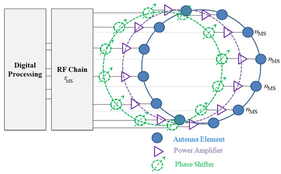
Figure 1.
Analog beamformer at the MS.
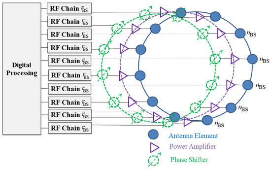
Figure 2.
Digital beamformer at the BS.
Additionally, UCA provides an enhanced performance when compared with uniform planar arrays (UPA) for the same number of antennas, since the latter features a rectangular perimeter that possesses separable current distributions among the elements. Consequently, this creates non-uniform radiation patterns. Note that UPA represents a two-dimensional extension of ULA; hence, it uses the same design procedures. As such linear analysis is directly applied to find the principal plane patterns, albeit a higher computational complexity due to the increased dimensionality. This multi-dimensionality enables UPA to support 2D scanning with symmetrical patterns at the detriment of increased side lobes and larger dimensions. Along these lines, this paper adopts UCA in the structure of the beamformer, since it outperforms ULA solutions that exhibit deficient directivity in the broadside directions and UPA designs with a rectangular perimeter that feature separable current distributions among the elements and increased complexity.
Along these lines, assuming a MS equipped with an analog beamformer realized using UCA, this UCA is composed of equally spaced antennas in the x-y plane arranged in a circular geometry with a radius of a. Each antenna is connected to a power amplifier to enhance the power density. Moreover, each antenna element is supported by one dedicated analog phase shifter in order to provide continuous beam scanning with parallel antenna feeds. Finally, the array connects to a frequency (RF) chain, , where is the total number of RF chains at the MS (set to 1 for analog beamformer). Figure 1 depicts the beamformer structure at the MS. The resultant beam conducts complete spatial transmission and reception in different pointing angles from one RF chain in cascaded codebook stages (i.e., each stage defines a set of directions of specific bandwidth). The directions are determined by combining vector of i = 1,2, …, I indices at (t) th time step, where I represents the number of pointing directions at the MS, as per Figure 3.
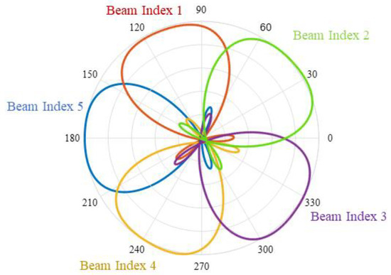
Figure 3.
Beam indices at the MS.
The use of analog beamforming at the MS is due to the limited power resources. On the contrary, BS can be supported with a higher input power due to its stationary nature (flexibility in space and size). Hence, digital beamforming solutions are adopted at the BS and are attributed to the abundant input power and the need to support multi-user connectivity support. Hence, consider a BS composed from antennas that are equally spaced in circular ring to form a UCA, where each antenna is connected to one power amplifier and phase shifter. Moreover, each antenna unit connects to one dedicated RF chain, (number of antennas is equal to the number of RF chains), as per Figure 3. The BS also generates beamforming vectors in various directions, i.e., j = 1, 2, …, J, where the variable J represents the number of BS directions. See Table 3 for a list of notations for the beamforming models.
Table 3.
List of notations for the beamforming model.
3.2. Signal and Channel Models
Consider a time division duplexing (TDD) transmission and reception mode in the mmWave channel to leverage reciprocity, where the channel state is determined beforehand and exchanged between the MS and MS. The downlink signal model at the MS is then formulated as,
where the variables , , , H, z and w represent the transmitted power level, the MS combining matrix composed of combining vectors, BS beamforming matrix composed of beamforming vectors, mmWave channel block, control or data signal, and the additive white Gaussian noise (AWGN), modeled as , where is the variance, respectively.
The channel here follows the geometric model due to the sparse structure, where the geometry of objects in the channel highly impact the number and distribution of rays in the received signal profile. In addition, the wavelengths are much smaller than the geometries of objects in the channel. The geometric channel is formulated as [12]
where denotes the blockage path loss and is the channel gain from path l L total paths (rays) that follow an exponential arrival rate in few K clusters that follow a Poisson rate. Note that the path gains follow a Rician distribution to account for the transition between Line-of-sight (LoS) and non-line-of-sight (NLOS), . Here the variable denotes the power ratio between the first arriving LoS ray and subsequent rays. Furthermore, the beamforming and combining matrices in Equation (1) determine the array response at the BS and MS, respectively. Here, the array factor (AF) is used to gauge the angular directions (azimuth and elevation ) along the array. Hence the AF for the MS, , is expressed as (similar approach is adopted at the BS) [29,30],
where is the n-th antenna amplitude at the MS, is the imaginary number, v symbolizes the wave-number, i.e., , where λ is the wavelength, , where is the speed of light and is the carrier frequency. The variable in Equation (3) denotes the n-th antenna angular position, expressed by . Finally, the variable is the principal radiation at the MS affiliated with vector at (t)th time step, expressed as,
3.3. Blockage Model
Blockage occurs when obstacles of different dimensions are present in the established direct link between the MS and BS that use the beamforming and combining vectors that resulted in the highest signal level. Now these beams are blocked, and the channel gain is changed accordingly in the form of an increased path loss. This is modeled as [31],
where the symbol represents an indicator function for status of the link (e.g., LoS or NLoS). Namely, if blockage occurs then (x) = 1 iff x = 1, whereas (x) = 0 in the absence of blockage effects. Moreover, and symbolize LoS and NLoS path loss parameters, respectively, and are calculated as [32],
Here, variable d denotes the separation distance between BS and MS, whereas variable is the reference distance. Additionally, the symbols and account for the path loss exponent (PLE) for the different link status (LoS and NLoS, respectively) In addition, variables and ( represent LoS and NLoS probabilities at a separation distance d. This probability is calculated as , where denotes the blockage parameter for objects of varying dimensions. See Table 4 for the list of notations for the channel models.
Table 4.
List of notations for the mmWave channel.
4. Proposed LSTM-Based Recovery Scheme
In general, neural networks lack memory blocks, which imposes challenges in predicting sequential data and time series. Hence, recurrent neural networks (RNN) introduce a feedback loop that injects past inputs back to the model, i.e., acting as memory. However, the storage is for short time periods. To solve this problem, LSTM networks are introduced to enhance the memory problem in RNNs by creating both short-term and long-term memory blocks in multiple stacked layers. Namely, the memory blocks (units) are comprised of self-connected cells and a multiplicative gate, thus enabling learn long term dependencies. This structure enhances the detection criterion in sequential and time-series forecasting. Furthermore, LSTM accepts random weight initializations and a variety of state information without the requirement of a prior setting of the input states. Moreover, LSTM networks overcome the problem of vanishing gradients. Finally, they feature low complexity as compared to alternative deep learning algorithms, i.e., the computational complexity per weight and time is modeled as backpropagation through time (BPTT), O(1) [33].
In the case of mmWave beam blockage problem, LSTM cells can store previous timestep information in its memory blocks, thus enhancing the beam index accuracy. Hence, four LSTM layers are stacked (chained) to achieve higher precision. The proposed LSTM method is comprised from three phases, i.e., input, hidden layers and output, where each hidden layer is represented by a LSTM cell, where each cell is composed of a state consisting of input , input modulation , forget and output gates that determine information entering the cell state. Along these lines, the prediction scheme adopts LSTM to achieve a suitable solution for time-series prediction of variable sequences lengths.
Along these lines, consider a MS and BS performing initial beam access procedure using traditional schemes in order to determine the beam directions (indices) that yield in the highest signal at (t)th time step, i.e., and . This also includes determining their affiliated best pointing directions. In notations,
Once blockage occurs (substituting 1 in the indicator function), then LoS-to-NLoS transition occurs, thus reducing channel capacity and spectral efficiency. Therefore, alternative directions are required here for link recovery and avoiding sessions drops. Specifically, once the instantaneous spectral efficiency (bits/sec/Hz) affiliated with the current beam falls below the threshold value expressed in Equation (9), then beam recovery scheme is triggered. The network then operates link recovery by operating in learning (Mode I) and training (Mode II) modes, as detailed later.
where Ω, and SNR in order are the loss factor, maximum spectral efficiency [34], and signal-to-noise ratio, respectively.
where the variable Ψ represents the Boltzmann constant, accounts for the operating temperature, and the variable denotes the bandwidth. and in Equation (10) are the array gains at the MS and BS, respectively, i.e., , and , where is the gain for one antenna. The architecture of the proposed LSTM network first proposed in [33] is now presented.
4.1. Network Architecture
The architecture of the used LSTM network is now illustrated in Figure 4, which depicts the different stages of the deep learning network, which is composed of the input sequences, four recurrent LSTM layers, a dense layer and an output layer. The input layer is connected to the LSTM layer. The recurrent connections in the LSTM layer are directly from the cell output units to the cell input units, input gates, output gates and forget gates. The cell output units are connected to the output layer of the network. The use of four layers is to enhance the efficiency and accuracy of the proposed algorithm. Meanwhile, a dense layer is used (matrix vector multiplication) for outputting a prediction. Here, each layer is composed of 50 cells (neurons), where each cell consists of an input, modulation gates, with operations and interconnections, as illustrated in Figure 5, i.e., input , input modulation , forget and output gates that determine information entering the cell state.
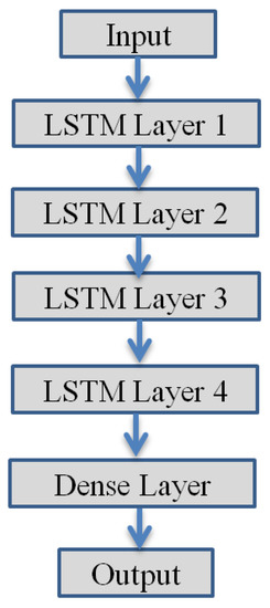
Figure 4.
Proposed LSRM network architecture.
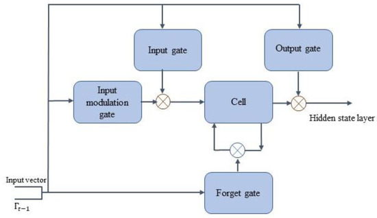
Figure 5.
LSTM cell structure.
The output of the last LSTM layer is fed as the input of the dense layer, which is composed of a linear activation function. The output of the dense layer presents the output of the proposed scheme, which is a beam index prediction at the (t + 1) th time step. The process of this LSTM-based beam prediction algorithm is now presented.
4.2. Operating Modes
The network operates in learning and training modes (I and II), as explained in the pseudocode in Algorithm 1.
| Algorithm 1 LSTM-Based Beam Prediction Algorithm against Link Blockage |
| Input:, , Mode I//Use conventional recovery schemes at (t)th time step, Collect Observations for Dataset < s.t. //signal drops below threshold value max(, ): ∈ && ∈, //Select the best pair at (t)th time step that return maximum signal. Output: Dataset that include multiple pairs of at different (t)th time steps. Mode II: // Training mode (trained network), use input dataset for LSTM-based recovery < s.t. //signal drops below threshold value Predict the next beam at (t + 1)th time step using LSTM network as per Figure 5. //Select the best pair at subsequent (t + 1)th time step that return maximum signal. |
Learning Mode (Mode I): The MS and BS perform a traditional recovery scheme to compute the best beams at (t) th time step. The network here operates in an early stage and it does not have enough labeled datasets from previous observations. When link blockage occurs, the MS and BS use conventional recovery schemes to select the best beam to compute the best beams at (t) th time step for learning period . However, the network here collects observed data during this learning period . Now if the signal level and the SNR at the MS drops below a threshold level, < and <, respectively, then the BS anticipates that a beam blockage will occur in the subsequent (t + 1) th time step, hence it aims to find an alternative beam indices , ) that yield the highest signal level and optimum SNR, i.e., y testing the signal strength and instantaneous capacity at every pair ∈ and ∈.
The result is a unique pair that results in the highest signal and instantaneous SNR, i.e., . The output of this mode is the best alternative pair and a labeled dataset after elapsed time period that include multiple pairs of at different (t) th time steps. During this mode, the MS and BS will feed their best beams at every time step into the deep learning algorithm for use during the training process. After the model is well-trained, the MS and BS estimate the next primary beam to be used if blockage occurs, as shown in Mode II.
Training Mode (Mode II): The network now has learned incoming traffic and indices of frequently blocked beams. When the signal level drops below the threshold level, < and <, then the link blockage prediction scheme leverages parametric information from previous time periods (t 1) th and then labels the next to predict the beam indices with the highest signal level . Now given the prediction status of the best beam at the (t) th time step. Then the recovery problem is formulated as a prediction of the best alternative direction at (t + 1) th time step during the training period, i.e., given the status at time t, i.e., maximize the prediction probability of link blockage and best subsequent beam. This mode constitutes the processing and training phases for the reconfigurable learning model and operates as follows.
Processing Phase: Each cell in the LSTM network is composed of a state consisting of input , input modulation , forget and output gates that determine information entering the cell state. Initially, the cell state, at time t determines information fed to the next sequence is modified by (remember vector) in the sigmoid layer, which is adjusted by that delivers the new candidate cell state. The forget gate then has the following inputs. A hidden state vector during the (t1) th time step, along with an input vector at the (t) th time step, . This gate then returns a number between 0 and 1 for each number in the previous cell state at the (t1) th time step, . Specifically, the output of specifies the information that the cell state need to forget or discard, i.e., by multiplying 0 to a specific position in the matrix. If the output of the remember vector is 1, then the cell state maintains this information. A sigmoid function, is applied here to the weighted input and previous hidden state. Equations (11)–(15) represent the cell state , and gates , , , and all at time step t, i.e.,
Parameters,,, are the weight matrices and , , are the bias vectors for the , and gates and the cell state, respectively, acquired during the training mode. Lastly, the hidden state layer is expressed as . See Table 5 for a complete list of notations for the LSTM deep learning network.
Table 5.
List of notations for the LSTM network.
The LSTM network iteratively maps an output sequence for each input sequence from t = 1 to T by calculating the unit activations, as per [33],
where the term W denotes the weight matrices (from the input gate to the input), , and denote in order the number of the memory cells (number of memory blocks), input units, and the output units. Overall, the key parameters in this learning and training phases include the logistic Sigmoid and the hyperbolic tanh nonlinear activation function used for the gates to estimate the output. Specifically, the input gate is modeled as a sigmoid function with a range ∈ [0,1] (adding memory only without forgetting), as the equation is a summation of the previous cell state. As a result, the gate is activated with a tanh activation function with a [−1, 1] range to enable the cell state to forget memory.
Training Phase: The training settings here are composed of 4 hidden layers and 50 LSTM units per each layer. The drop-out regularization rate in each layer is set at 0.2. Furthermore, the model is trained with 350 epochs over a 2-week period. Along these lines, a data structure with 60 steps (each of 10 min) and a single output is created, as the LSTM cells store long-term memory state. Thus, there are 60 previous training set elements for every recorded sample in each training stage. Hence, in the testing stage, the first 60 samples are required to achieve an accurate prediction for the subsequent best beam index.
The learning computational complexity for the LSTM-based network per weight in a single time step t is gauged as O (W). Overall, the computational complexity here is at acceptable levels, since the number of inputs and memory cells is relatively small. However, this complexity increases for larger number of output units and memory cells.
5. Simulation Results and Performance Evaluation
The overall training goal here is to determine weight matrices, gauge the bias vectors that reduce the loss model for the entire time steps during the training phase, as modeled next. See Table 6 for the overall parametric settings selected for the layers in the LSTM network.
Table 6.
Parameter settings for the LSTM Model.
Dataset: The work here leverages and applies the BigData Challenge dataset in [35] collected in the City of Milan. This dataset studies the behavior of subscribers (MSs) in sectorized geographical grids (each of 200 m), in terms of the requested data forms, such as call-in, call-out, SMS-in, and SMS-out.
Figure 6 shows the LSTM network predicts the beam index over various time steps at the MS (likewise at the BS), i.e., beam index used in order to achieve link recovery once a blockage is introduced. It is noticed here that index i = 5 features the highest popularity class among other indices. The scheme also yields a high approximation between the ground truth and prediction pattern. Namely, the proposed scheme achieves high accuracy and thereby it can successfully predict the subsequent beam indices with high success probabilities, once the network is sufficiently trained. Moreover, the accuracy of the proposed scheme is further studied by computing the loss function shown in Figure 7.
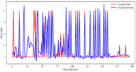
Figure 6.
LSTM-based beam index prediction.
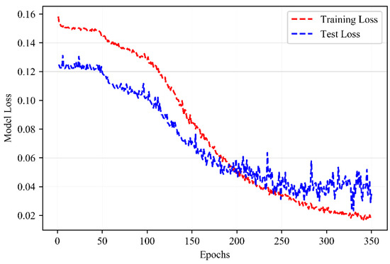
Figure 7.
LSTM-based model loss.
Loss Function: The training goal aims to reduce the loss model, which is represented in the form of the mean square error (MSE) between the prediction vector and the actual ground truth at the upcoming time step, is evaluated over U predictions points. Note that both the prediction model and the ground truth have the same distribution over the same time period. The loss function for every (t1) th time step is modeled as,
Figure 7 depicts the error function for the proposed scheme versus the ground truth computed over 350 epochs. Here, the reduced MSE achieves approximate fit, which enhances accuracy and success probability of the proposed recovery scheme. The proposed beam restoration method due to blockage leveraging the deep learning model is now compared and assessed versus existing prominent schemes in the literature, in terms of recovery times and energy consumption. See Table 7 for the overall system parametric settings.
Table 7.
System parameters.
5.1. Recovery Times
The link recovery (restoration) time at the MS and BS ( and ) is a key evaluation metric for beamforming-based mmWave networks. This parameter is measured for the proposed scheme, as depicted Figure 8. It accounts for the scan time period needed to specify a new (best) spatial direction that yields the highest signal level and its affiliated best beam at both the MS and BS. Figure 8 shows that the scheme features near-instantaneous recovery times. This is attributed to the prior prediction of the subsequent directions and their associated beam indices using the deep learning algorithm in the case of blockage. Thus, it eliminates the requirements to reset beam scanning, unlike conventional schemes. For example, it only requires transmitting the primary synchronization signals (PSS) duration over the beamforming (or combining) vectors. It is important to note that this value is fixed regardless of the blockage intensity or the density of the objects. Along these lines, the proposed recovery scheme features fast recovery times (approx. 200 μs) versus 500 μs for the link recovery technique in [9], 9600 μs for the codebook designs in [2,3], and 7100 μs for the metaheuristics-based recovery scheme.
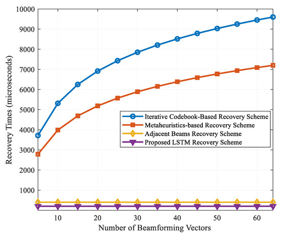
Figure 8.
Recovery times for various beamforming vectors.
5.2. Energy Consumption
Although the recovery times achieved here are similar to the ones achieved in [7,8], however this has the benefits of reduced energy consumption levels and enhanced robustness to blockage intensity. Figure 9 shows the energy consumption measured at the MS (similar behavior at the BS), which is defined as the power consumed by the RF-frontend during beam restoration times. This variable is modeled as , where denotes the power consumption level in the analog beamformer at the MS. Table 7 lists the notations for the power model, formulated as,
where ,, , , , , , , , are the power consumption values for a single microstrip antenna, the phase shifter (PS), low noise amplifier (LNA), radio frequency (RF) chain, analog-to-digital converter (ADC), baseband combiner (BB), mixer (M), local oscillator (LO), low pass filter (LPF) and the baseband amplifier (AMP), respectively. Moreover, the variable denotes the energy consumption per conversion in the ADC, accounts for the sampling rate and finally the variable is the number of bits [36]. The power consumption values (in milliwatts) for these components are listed in Table 8, recorded from settings in [37]. The energy consumption levels plotted in Figure 9 show that the proposed scheme yields very low energy levels compared to other schemes.
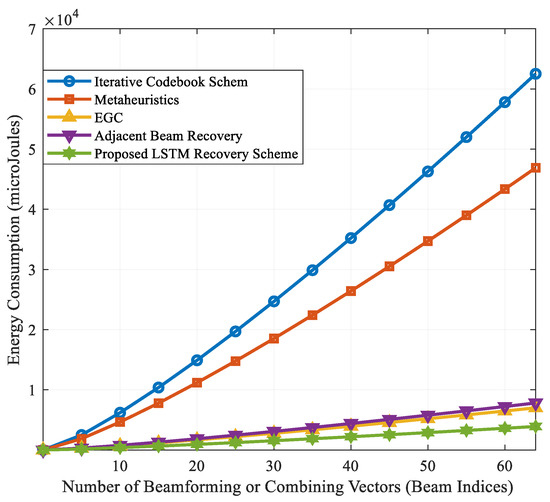
Figure 9.
Energy consumption for various beamforming vectors.
Table 8.
List of notations for the power consumption model.
The energy efficiency here is attributed to the reduced time using the RF chains. For example, the deep learning scheme requires 4 millijoules (mJ) to perform link recovery when using 64 beams. Meanwhile, the iterative, metaheuristics, beam aggregation and adjacent beam recovery methods require 60, 48, 9 and 8 mJ, respectively. Overall, the proposed scheme achieves 50% better energy efficiency and 25% reduced access times compared to the closest scheme, i.e., adjacent link recovery method [6]. Moreover, it outperforms the iterative scheme by 93%, the metaheuristic schemes in [3,4] by 91% and the beam aggregation method in [5] by 55%.
Overall, the proposed LSTM-based beam prediction scheme presents key findings in mmWave communications. First, the near-instantaneous recovery times promote service continuity, enhanced QoS and saves in network resources since it does not occupy frequency or spatial resources to recover the defected beam. Moreover, the low power and energy consumption levels allow for realistic transceiver architecture at the MS with reduced heat exposure. Furthermore, the proposed scheme is implemented on a highly directional antennas at the MS and BS, without reliance on omni-directional modes, this magnifies the signal strength and channel capacity during the beam access and restoration phases.
6. Conclusions
This paper presents a novel link recovery scheme for mmWave-based transceivers operating in the FR2 bands of the standalone 5G NR access technology. The scheme leverages long short-term memory deep learning and operates in two modes, i.e., learning and training, where best beamforming and combining vectors learnt during past link blockage are leveraged as the input to the learning model. The scheme achieves near-instantaneous recovery times in highly directional beam transmission, i.e., maintaining communications sessions without resetting beam scanning procedures. Future efforts will investigate deep learning models that incorporate user mobility at different speeds and the impact of the beamwidth on the channel coherence times, where an analytical model that relates these quantities is required for mmWave communications.
Author Contributions
Conceptualization, A.A., F.S. and M.J.; methodology, A.A. and M.J.; software, F.S.; validation, A.A., F.S. and M.J.; formal analysis, M.J.; investigation, M.J.; resources, A.A.; data curation, F.S.; writing—original draft preparation, A.A., F.S. and M.J.; writing—review and editing, M.J.; visualization, A.A.; supervision, A.A. and M.J.; project administration, A.A.; funding acquisition, A.A. All authors have read and agreed to the published version of the manuscript.
Funding
This research was funded by the Deanship of Scientific Research at King Faisal University, grant number 1811025.
Institutional Review Board Statement
Not applicable.
Informed Consent Statement
Not applicable.
Acknowledgments
The authors acknowledge the Deanship of Scientific Research at King Faisal University for the financial support under the research group support track (Grant No: 1811025).
Conflicts of Interest
The authors declare no conflict of interest.
References
- International Mobile Telecommunications. Minimum Requirements Related to Technical Performance for IMT-2020 Radio Interface; ITU-R Study Group 5: Geneva, Switzerland, 2017; pp. 6–7. [Google Scholar]
- Alkhateeb, A.; El Ayach, O.; Leus, G.; Heath, R.W. Channel estimation and hybrid precoding for millimeter Wave cellular systems. IEEE J. Sel. Top. Signal Process. 2014, 8, 831–846. [Google Scholar] [CrossRef]
- Jasim, M.; Ghani, N. Generalized pattern search for beam discovery in millimeter Wave systems. In Proceedings of the IEEE 86th Vehicular Technology Conference (VTC-Fall), Toronto, ON, Canada, 24–27 September 2017. [Google Scholar]
- Jasim, M.; Aldalbahi, A.; Khreishah, A.; Ghani, N. Hooke Jeeves search method for initial beam access in 5G mmWave cellular networks. In Proceedings of the IEEE 28th Annual International Symposium on Personal, Indoor, and Mobile Radio Communications (PIMRC), Montreal, QC, Canada, 8–13 October 2017. [Google Scholar]
- Jasim, M.; Aldalbahi, A.; Shakhatreh, H. Beam aggregation for instantaneous link recovery in millimeter Wave communications. In Proceedings of the IEEE International Conference on Wireless and Mobile Computing, Networking and Communications (WIMOB), Limassol, Cyprus, 15–17 October 2018. [Google Scholar]
- Jasim, M.; Ababneh, M.; Siasi, N.; Ghani, N. Hybrid beamforming for link recovery in millimeter Wave communications. In Proceedings of the IEEE Wireless and MicroWave Technology Conference (WAMICON), Clearwater, FL, USA, 9–10 April 2018. [Google Scholar]
- Jasim, M.; Ababneh, M.; Siasi, N.; Ghani, N. Soft self-handover scheme for mm Wave communications. In Proceedings of the IEEE Southeast Conference, Huntsville, AL, USA, 11–14 April 2019. [Google Scholar]
- Jasim, M.; Aldalbahi, A. Diversity coding for instantaneous link recovery in millimeter Wave communications. In Proceedings of the IEEE International Symposium on Signal Processing and Information Technology (ISSPIT), Louisville, KY, USA, 6–8 December 2018. [Google Scholar]
- Gao, B.; Xiao, Z.; Zhang, C.; Su, L.; Jin, D.; Zeng, L. Double-link beam tracking against human blockage and device mobility for 60-GHz WLAN. In Proceedings of the IEEE Wireless Communications and Networking Conference (WCNC), Istanbul, Turkey, 6–9 April 2014. [Google Scholar]
- Kim, W.; Song, J.; Baek, S. Relay-assisted handover to overcome blockage in millimeter-Wave networks. In Proceedings of the IEEE 28th Annual International Symposium on Personal, Indoor, and Mobile Radio Communications (PIMRC), Montreal, QC, Canada, 8–13 October 2017. [Google Scholar]
- Giordani, M.; Mezzavilla, M.; Rangan, S.; Zorzi, M. An efficient uplink multi-connectivity scheme for 5G millimeter-Wave control plane applications. IEEE Trans. Wirel. Com. 2018, 17, 6806–6821. [Google Scholar] [CrossRef]
- Alkhateeb, A.; Beltagy, I.; Alex, S. Machine learning for reliable mm Wave systems: Blockage prediction and proactive handoff. In Proceedings of the IEEE Global Conference on Signal and Information Processing (GlobalSIP), Anaheim, CA, USA, 26–29 November 2018. [Google Scholar]
- Wang, Y.; Narasimha, M.; Heath, R.W. Mm Wave beam prediction with situational awareness: A machine learning approach. In Proceedings of the 2018 IEEE 19th International Workshop on Signal Processing Advances in Wireless Communications (SPAWC), Kalamata, Greece, 25–28 June 2018. [Google Scholar]
- Anton-Haro, C.; Mestre, X. Learning and data-driven beam selection for mmWave communications: An angle of arrival-based approach. IEEE Access. 2019, 7, 20404–20415. [Google Scholar] [CrossRef]
- Wenyan, M.; Qi, C.; Li, G.Y. Machine learning for beam alignment in millimeter Wave massive MIMO. IEEE Wirel. Comm. Lett. 2020, 9, 875–878. [Google Scholar]
- Xu, C.; Liu, S.; Zhang, C.; Huang, Y.; Yang, L. Joint user scheduling and beam selection in mmWave networks based on multi-agent reinforcement learning. In Proceedings of the IEEE 11th Sensing Array Multichannel Signal Processing Workshop (SAM), Hangzhou, China, 8–11 June 2020. [Google Scholar]
- Alrabeiah, M.; Alkhateeb, A. Deep learning for mmWave beam and blockage prediction using sub-6 GHz channels. IEEE Trans. Com. 2020, 68, 5504–5518. [Google Scholar] [CrossRef]
- Göttsch, F.; Megumi, K. Deep learning-based beamforming and blockage prediction for sub-6GHz/mmWave mobile networks. In Proceedings of the 2020 IEEE Global Communications Conference (GLOBECOM), Madrid, Spain, 7–11 December 2020. [Google Scholar]
- Yang, W.H.; Kuang-Hao, L. Blockage effect and beam cooperation in indoor hotspot based on 3GPP NR blockage model. In Proceedings of the 2019 IEEE International Conference on Communications (ICC), Shanghai, China, 20–24 May 2019. [Google Scholar]
- Bhattacharjee, A.; Ratnajit, B.; Sanjay, K.B. DC-DLLR: A MAC layer approach for reliable and blockage tolerant mmWave indoor networks. In Proceedings of the 2021 International Conference on Communication Systems & Networks (COMSNETS), Bangalore, India, 5–9 January 2021. [Google Scholar]
- Arijit, B.; Ratnajit, B. An approach for mitigation of beam blockage in mmWave based indoor networks. IEEE Internet Things J. 2021, 1–6. [Google Scholar] [CrossRef]
- Gu, T.; Zhicheng, Y.; Prasant, M. BeamSniff: Enabling seamless communication under mobility and blockage in 60 GHz networks. In Proceedings of the 2019 IFIP Networking Conference (IFIP Networking), Warsaw, Poland, 20–22 May 2019. [Google Scholar]
- Alrabeiah, M.; Hredzak, A.; Alkhateeb, A. Millimeter Wave base stations with cameras: Vision-aided beam and blockage prediction. In Proceedings of the 2020 IEEE 91st Vehicular Technology Conference (VTC2020-Spring), Online, 25–28 May 2020. [Google Scholar]
- Jia, C.; Hui, G.; Na, C.; Yuan, H. Machine learning empowered beam management for intelligent reflecting surface assisted MmWave networks. China Commun. 2020, 17, 100–114. [Google Scholar] [CrossRef]
- Gerasimenko, M.; Dmitri, M.; Margarita, G.; Sergey, A.; Yevgeni, K. Capacity of multi-connectivity MmWave systems with dynamic blockage and directional antennas. IEEE Trans. Veh. Tech. 2019, 68, 3534–3549. [Google Scholar] [CrossRef]
- You, L.; Chen, X.; Song, X.; Jiang, F.; Wang, W.; Gao, X.; Fettweis, G. Network massive MIMO transmission over millimeter-Wave and terahertz bands: Mobility enhancement and blockage mitigation. IEEE J. Sel. Areas Commun. 2020, 38, 2946–2960. [Google Scholar] [CrossRef]
- Zheng, C.; Liu, S.; Huang, Y.; Yang, L. MEC-enabled wireless VR video service: A learning-based mixed strategy for energy-latency tradeoff. In Proceedings of the 2020 IEEE Wireless Communications and Networking Conference (WCNC), Seoul, South Korea, 25–28 May 2020. [Google Scholar]
- Rahman, A.U.; Gourab, G. A beam-switching scheme for resilient mmWave communications with dynamic link blockages. In Proceedings of the 2019 International Symposium on Modeling and Optimization in Mobile, Ad Hoc, and Wireless Net-works (WiOPT), Avignon, France, 27–31 May 2019. [Google Scholar]
- Balanis, C. Antenna Theory: Analysis and Design, 3rd ed.; Wiley & Sons: Hoboken, NJ, USA, 2005; pp. 290–304. [Google Scholar]
- Stutzman, W.; Thiele, G. Antenna Theory and Design, 3rd ed.; Wiley & Sons: Hoboken, NJ, USA, 2012; pp. 626–629. [Google Scholar]
- Bai, T.; Desai, V.; Heath, R.W. Millimeter Wave cellular channel models for system evaluation. In Proceedings of the International Conference on Computing, Networking and Communications (ICNC), Honolulu, HI, USA, 3–6 February 2014. [Google Scholar]
- Sun, S.; Rappaport, T.R.; Rangan, S.; Thomas, T.A.; Ghosh, A.; Kovacs, I.Z. Propagation path loss models for 5G urban micro- and macro-cellular scenarios. In Proceedings of the IEEE 83rd Vehicular Technology Conference (VTC2016-Spring), Nanjing, China, 15–18 May 2016. [Google Scholar]
- Akdeniz, M.R.; Liu, Y.; Samimi, M.K.; Sun, S.; Rangan, S.; Rappaport, T.S.; Erkip, E. Millimeter Wave channel modeling and cellular capacity evaluation. IEEE JSAC 2014, 32, 1164–1179. [Google Scholar] [CrossRef]
- Sepp, H.; Schmidhuber, J. Long short-term memory. Neural Comput. 1997, 9, 1735–1780. [Google Scholar]
- Italia, T. Telecommunications–SMS, Call, Internet–MI. Hardvard Dataverse 2015. [Google Scholar] [CrossRef]
- Abbas, W.D.; Zorzi, M. Context information based initial cell search for millimeter Wave 5G cellular networks. In Proceedings of the European Conference on Networks and Communications (EuCNC), Athens, Greece, 27–30 June 2016. [Google Scholar]
- Méndez-Rial, R.; Rusu, C.; Alkhateeb, A.; González-Prelcic, N.; Heath, R.W. Channel estimation and hybrid combining for MmWave: Phase shifters or switches? In Proceedings of the Information Theory and Applications (ITA) Workshop, San Diego, CA, USA, 1–6 February 2015. [Google Scholar]
Publisher’s Note: MDPI stays neutral with regard to jurisdictional claims in published maps and institutional affiliations. |
© 2021 by the authors. Licensee MDPI, Basel, Switzerland. This article is an open access article distributed under the terms and conditions of the Creative Commons Attribution (CC BY) license (https://creativecommons.org/licenses/by/4.0/).