Abstract
In the ergonomic design of wearable products such as an oxygen mask, systematic design methods including the analysis of anthropometric information, evaluation of fit, and product design need to utilize 3D human scan data. The present study intends to develop a virtual fit analysis method that generates an ergonomic shape of an oxygen mask for fighter pilots based on 3D facial scans. The proposed virtual fit analysis method enables iteratively to revise the shape of an oxygen mask until an appropriate level of fit between the mask and a group of pilot faces is achieved. The proposed method of virtual fit analysis and design optimization was applied to find ergonomic shapes of oxygen masks for four size categories (small narrow, medium narrow, medium wide, and large wide) to accommodate 336 pilots of the Republic of Korea Air Force. The virtual fit analysis results in the study showed that the revised oxygen mask shapes achieved significantly higher accommodation percentages (4.8~88.7%) at facial areas (nasal root, nasal side, cheek, and chin) compared to the existing oxygen mask shapes. The proposed method can be applied to develop an ergonomic product design that fits the face and other human body parts.
1. Introduction
A pilot oxygen mask worn over the face of a fighter pilot requires an ergonomic design that comfortably fits the face of the pilot. The pilot oxygen mask provides the pilot with oxygen while a mission is conducted at a high altitude where oxygen is lacking [1]. In addition, the pilot oxygen mask protects the pilot by supplying oxygen securely in a hazardous situation such as decompression, fire and fume in the cockpit, and windblast during ejection [2]. A pilot mask lacking the consideration of the facial characteristics of the user population can cause discomfort, pain, and/or leakage of air at some facial areas, especially around the nasal root [1,3].
Although the facial characteristics of the user population need to be considered to design an ergonomic shape and size of a mask, the analysis of the fit of a mask to the user population has not been considered sufficiently. Existing studies [4,5,6,7,8,9,10] recommend face length, face width, lip width, nasal root breadth, and nose protrusion as key facial dimensions for mask design. However, measurements of the key facial dimensions are not sufficient in designing the ergonomic shape and size of a mask that properly accommodates the faces of the user population due to the high complexity and diversity of the face shape and size among the users [11,12]. Several studies [13,14,15,16] introduced mask design methods using the information of 3D facial shapes as well as facial sizes. Gross et al. [15] reported an improved design of MBU-20/P (Gentex Corporation, Simpson, PA, USA) pilot oxygen mask using the profile curves of the 3D scanned faces of 30 male and 30 female pilots of the U.S. Air Force. Han et al. [14] designed an industrial respiratory mask of three sizes (small, medium, and large) for Korean industry workers using 3D representative head models identified by analyzing Korean faces. Lastly, Zhuang et al. [13] used five 3D head forms representing U.S. workers in designing an industrial respiratory mask. However, the validation of a design with a large group of users is often limited due to time and cost [17,18,19]; therefore, a computerized method would be a practical solution for design validation with a large number of virtual individuals [20,21].
A virtual fit analysis method that simulates the fit of a product design using the 3D face images of users and the CAD of the product still lacks its applicability to developing an ergonomic design of mask which is optimized for a large number of users. Virtual fit analysis methods have been introduced in designing wearable products such as clothing [22,23,24,25], helmet [26,27], and mask [15,21,28]. The previous studies focus on the analysis of fit between a product and the human body under a particular placement condition (e.g., the placement of a product to a predefined location of the human body) or the development of a custom design for a particular user. Studies including Dai et al. [29] and Lei et al. [30] applied the finite element analysis (FEA) using an FEA program such as ANSYS (ANSYS Inc., Canonsburg, PA, USA) to analyze the fit of a mask by estimating the contact pressure of a mask to the face. However, very few face models and mask designs were considered in the FEA studies due to the complex procedure and high demand of time to manipulate 3D face images and mask designs in an FEA program. Thus, the FEA approach shows limited applicability to virtual fit simulation for a large number of 3D faces (say, over 100 faces) in developing an ergonomic design of mask that is appropriate to a designated percentage (say, 90%) of the target population. Furthermore, an efficient method for virtual design validation and design optimization needs to be explored.
The present study is intended to develop a virtual fit analysis method to develop an ergonomic design of a pilot oxygen mask for a particular user population. The virtual fit analysis method investigating the levels of fit of mask design candidates to 3D faces of a user population is explained in Section 2. Then, the application of the proposed method to improve the existing design of MBU-20/P pilot oxygen mask for a better fit to the faces of Korean Air Force (KAF) pilots is demonstrated as a case study in Section 3.
2. Design Method of Pilot Oxygen Mask Based on Virtual Fit Analysis
Three types of information are considered in virtual fit analysis for designing the shape and size of a mask: (1) 3D facial scan images and face measurements of the user population, (2) the boundary shape on which the mask contacts the face, and (3) the wearing positions of the mask on the face. An ergonomic design of the mask is searched by analyzing the distances between the mask boundary and 3D faces. The virtual fit analysis method proposed in the study is presented in the following subsections.
2.1. Information Required for Virtual Fit Analysis
2.1.1. 3D Facial Scan Images and Face Measurements
Three-dimensional (3D) face mesh surfaces are prepared and then facial landmarks such as sellion, supramentale, and cheilion considered in mask design [1] are identified on the 3D facial images. Then, face dimensions considered in mask design such as sellion-to-supramentale length and lip width (bi-cheilion distance) [1,15] are measured using the facial landmarks.
2.1.2. Boundary of Pilot Oxygen Mask
As shown in Figure 1, the gourd-shaped part of the mask contacting the face is designed by forming a line connecting design landmarks on the mask using spline interpolation. The mask design landmarks are defined as points that form the mask boundary using a spline curve [15,31]. The locations of the design landmarks are determined by considering the shape of facial features such as the root and sides of the nose and the sides and bottom of the lip for a natural fit of the mask boundary to the face. For example, as shown in Figure 1, the boundary of the existing MBU-20/P pilot oxygen mask proposed by Gross et al. [15] is drawn by connecting eight design landmarks: a nasal root point (D1), two nasal side points (D2 and D3), two cheek points (D4 and D5), two chin side points (D6 and D7), and a bottom lip point (D8). Note that the mask boundary can be modified by adjusting the locations of the design landmarks or adding/removing design landmarks.
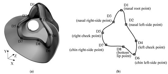
Figure 1.
A design of a pilot oxygen mask based on a mask boundary (perspective view): (a) design of a pilot oxygen mask; (b) a boundary of a mask drawn by a spline curve connecting eight design landmarks.
2.1.3. Mask-Wearing Positions
The wearing positions of a pilot oxygen mask on the face are identified using 3D scan images of the mask and the face and the information of the mask design landmarks and facial landmarks, as illustrated in Figure 2. The mask, face, and face worn with the mask are scanned separately (Figure 2a–c), and then the individual scan images of the mask and face are overlaid to that of the mask-worn face (Figure 2d). This superposition approach is conducted by referring to the previous studies on the virtual alignment of a product on a particular human body part [15,32]. Lastly, the wearing positions of the mask on the face are identified by measuring the vertical and horizontal distances between the mask design landmarks such as D1 (nasal root point) and D8 (bottom lip point) and the facial landmarks such as sellion and supramentale (Figure 2e). The quantitative data (average, SD, and range) of the mask-wearing positions are used for the placement of a 3D mask design model to a 3D face scan image in the virtual fit analysis of a mask design. The mask-wearing position information is important for the analysis of distances between a particular mask design and various faces while applying the same placement strategy of the mask to the faces.
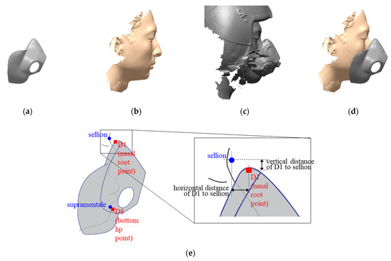
Figure 2.
Identification of mask-wearing positions using 3D scan images of a pilot face and an oxygen mask (illustrated). (a) 3D scan image of an oxygen mask; (b) 3D face scan image without wearing the mask; (c) 3D face scan image wearing the oxygen mask; (d) 3D scan images of the mask and the face overlaid to the 3D face scan image wearing the mask; (e) identification of the mask-wearing positions based on the mask design landmarks (■) and facial landmarks (⬤).
2.2. Ergonomic Mask Design by Virtual Fit Analysis
A virtual fit analysis method is developed to find the most ergonomically optimized boundary of the mask by virtually fitting the mask to various 3D faces. First, the boundary of a mask is virtually located over a 3D face at the identified mask-wearing positions. After virtual fitting of the mask to the face, the horizontal distances between the boundary of the mask and the surface of the 3D face are calculated along the vertical axis with an interval of 1% of the mask length, as illustrated in Figure 3a; in the plot, the facial area of which horizontal distance <0 mm (red area in Figure 3a) indicates the mask boundary region not contacting the face (causing oxygen leakage), while the opposite penetrating the face (causing contact pressure to the face). Next, the interface area of the mask and the face is divided into five sections along with the vertical location from the top: 0% to 10% for the nasal root area, 10% to 50% for the nasal side area, 50% to 90% for the cheek area, and 90% to 100% for the chin area. Figure 3b plots the horizontal distances of a designated group of faces (e.g., n = 29 pilot faces belonging to the small narrow size group) from the mask boundary, showing negative horizontal distances at the nasal root and positive horizontal distances at the other face sections. A virtual fit analysis program was coded using MATLAB (MathWorks, Inc., Natick, MA, USA) in the present study to analyze horizontal distances between the mask boundary and 3D face surfaces.
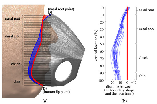
Figure 3.
Virtual fit analysis by calculating horizontal distances between the mask boundary and 3D face surfaces (illustrated). (a) Horizontal distances between the mask boundary and the face surface along the vertical axis with an interval of 1% of the mask length (blue line: mask boundary; red line: face surface, red shaded area: mask boundary region of negative horizontal distances causing oxygen leakage; blue shaded area: mask boundary region of positive horizontal distances causing contact pressure to the face); (b) plots of the horizontal distances between the mask boundary and face surfaces of a small narrow size group (n = 29).
An ergonomically optimized shape of the mask boundary for a designated user group is searched by an iterative design process and virtual fit analysis shown in Figure 4. In the first step (S1), an initial shape of the mask boundary is prepared by generating a spline curve that connects the design landmarks corresponding with positions on the face with the average size for the user group. In the second step (S2), the horizontal distances between the mask boundary and 3D face surfaces of the user group are calculated. In the third step (S3), the plots of the horizontal distances are evaluated to determine the appropriateness of the mask boundary for the designated user group. Note that the present study used a range of proper fit along the face sections identified by a usability evaluation survey of the MBU-20/P oxygen mask (described in Section 3.2) to evaluate the appropriateness of a mask boundary. In the fourth step (S4), the mask boundary is modified by adjusting the locations of the design landmarks in case that the mask boundary is found unsatisfactory for the designated user group. Repeat S2 to S4 until a satisfactory mask boundary is found. Lastly, in the fifth step (S5), a complete design of the mask is developed based on the selected mask boundary.
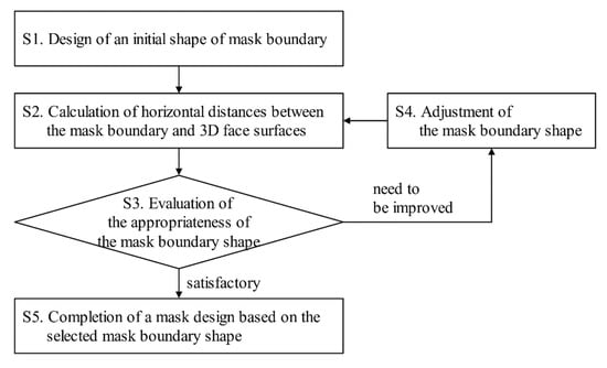
Figure 4.
An ergonomic design process of a pilot oxygen mask by virtual fit analysis.
3. Application to Virtual Fit Analysis Method to Pilot Oxygen Mask Design
The oxygen mask design method based on virtual fit analysis proposed by the present study was applied to improve the existing design of MBU-20/P pilot oxygen mask for Korean Air Force (KAF) pilots.
3.1. Acquisition of Information for Virtual Fit Analysis
3.1.1. KAF Pilots’ Facial Scan Images
Three-dimensional (3D) scan images of 336 KAF pilots and cadets (278 males and 58 females) obtained in our previous study [1] were used to improve the existing oxygen mask design in the present study. The 3D scan images of pilots were collected using the 3D scanner Rexcan 560 (Solutionix Co., Seoul, South Korea) and then eighteen facial dimensions were measured. Four mask size groups and pilots belonging to each size group (small narrow: 34, medium narrow: 121, medium wide: 76, and large wide: 105) were identified by applying a sizing system generation method [33,34,35] based on sellion-to-supramentale length and lip width (key facial dimensions of MBU-20/P) as shown in Figure 5a and four representative face models (RFMs) were found for each size group as shown in Figure 5b [35]. Of the KAF pilots and cadets, the profiles of 85 male pilots (small narrow: 21, medium narrow: 23, medium wide: 19, and large wide: 22) were photographed while wearing their current oxygen masks to examine the mask-wearing positions.
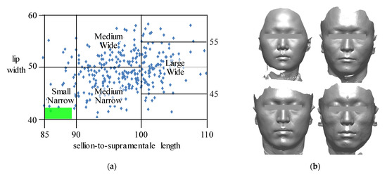
Figure 5.
An oxygen mask sizing system and representative face models for Korean Air Force pilots. (a) A sizing system of MBU-20/P oxygen mask for Korean Air Force pilots; (b) representative face models of the oxygen mask sizing system.
3.1.2. Design of Alternative Shapes of Mask Boundaries
Alternative boundary shapes to improve the existing oxygen masks for KAF pilots were prepared by projecting the design landmarks of existing oxygen masks onto the RFMs of KAF pilots. As shown in Figure 6, design landmarks D2 to D7 of the MBU-20/P oxygen mask specified by Gross et al. [15] were projected onto an RFM, while D1 (nasal root point) and D8 (bottom-lip point) are positioned to the sellion and supramentale on the RFM. Then, the projected design landmarks are connected by the drawing function of spline curve in Rhino 3D (Robert McNeel and Associates, Seattle, WA, USA) as shown in Figure 7b for an alternative boundary of the oxygen mask for the KAF pilots. Note that the alternative mask boundary is flatter than that of the existing mask boundary, as shown in Figure 7c.
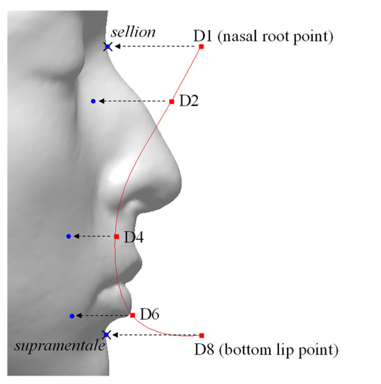
Figure 6.
Projection of design landmarks of the existing MBU-20/P mask onto a representative face of the Korean Air Force (KAF) pilots (red ■: design landmarks of MBU-20/P specified by Gross et al. [15]; blue ⬤: projected design landmarks on the face surface; ×: facial landmarks).

Figure 7.
Boundaries of the existing and alternative oxygen masks. (a) The boundary of the existing MBU-20/P oxygen mask based on design landmarks specified by Gross et al. [15]; (b) a boundary based on adjusted design landmarks identified by the projection of the existing design landmarks onto a representative face model of the Korean Air Force pilots; (c) the difference of the existing and alternative mask boundaries.
3.1.3. Identification of Mask-Wearing Positions
The mask-wearing positions of the oxygen masks of the four size categories were identified based on the profile photos of the 85 KAF pilots while wearing their MBU-20/P oxygen masks. The identification of mask-wearing positions was conducted in a four-step procedure. First, the profile face of a pilot while wearing his/her own oxygen mask was photographed by a digital camera (Figure 8a). Second, the digital photo was printed on a transparent film and placed on a PC monitor (Figure 8b). Third, the 3D face scan of the pilot and the CAD model of the mask were aligned manually with the face and mask images of the printed film (Figure 8c) using RapidForm 2006 (INUS Technology, Inc., Seoul, South Korea). Lastly, the mask-wearing positions were identified by measuring the Euclidian distances between the facial landmarks (sellion and supramentale) and mask design landmarks (D1 and D8), as summarized in Table 1.

Figure 8.
A photo-based placement of the 3D face and mask images for the identification of mask-wearing positions (illustrated). (a) A profile photo of a pilot while wearing the MBU-20/P oxygen mask; (b) a transparent film with a printed photo placed on the monitor; (c) an alignment of the 3D face and mask images to their corresponding images of the printed photo on the film.

Table 1.
Mask-wearing positions (unit: mm) for four mask size categories.
3.2. Design of Pilot Oxygen Mask by Virtual Fit Analysis
Ergonomic boundary shapes were derived for the oxygen masks of the four size categories (small narrow, medium narrow, medium wide, and large wide) by an iterative process of the five-step design approach by virtual fit analysis in Figure 4. In the first step (S1), initial mask boundaries were prepared by projecting the design landmarks of the existing oxygen masks onto the corresponding RFMs in Figure 5b and then each mask boundary was placed on the 3D face images (small narrow: 34, medium narrow: 121, medium wide: 76, and large wide: 105) which belong to corresponding size group by considering the mask-wearing positions in Table 1. In the second step (S2), the horizontal distances between the mask boundaries and the 3D face surfaces were calculated. In the third step (S3), the appropriateness of each mask boundary was assessed for each face section in terms of accommodation percentage (Equation (1)), which indicates the proportion of horizontal distances within the lower and upper limits for each vertical location (indicated by two red lines in Figure 9). Note that the lower and upper limits of the horizontal distance between mask boundary and face surface by face section for each mask size category were identified by analyzing, out of the 82 pilots, the profile photos of those satisfied with their oxygen masks at a usability evaluation survey of MBU-20/P oxygen mask conducted by Lee [35]. In the fourth step (S4), each mask boundary was modified by adjusting the locations of the design landmarks. The steps S2 to S4 were iterated until an appropriate boundary was found for each mask size category. Lastly, in the fifth step (S5), the oxygen mask design was completed for each mask size category by combining the appropriate mask boundary and the outer parts (Figure 1a).
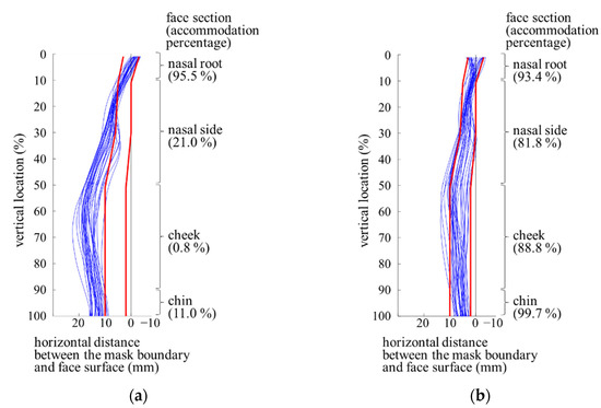
Figure 9.
Virtual fit analysis results of the existing and alternative designs of pilot oxygen mask boundary (size: small narrow; red lines: the lower and upper limits of appropriate fit; blue lines: plots of the horizontal distances between the mask boundary and face surfaces). (a) Existing design; (b) alternative design.
- and
- .
The accommodation percentages of the revised mask boundaries derived through the virtual fit analysis method for the four sizing categories were found 4.8~88.7% higher than those of the existing boundary shapes over the face sections for KAF pilots. The accommodation percentages at the nasal side, cheek, and chin areas showed noticeable improvements for proper fit of the mask to the face (Figure 10). All the accommodation percentage differences between the existing and revised masks except two conditions (SN and MW at the nasal root) were found significant by the paired t−test at α = 0.05.
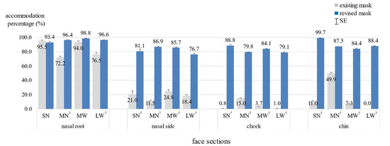
Figure 10.
Comparison of the accommodation percentages of the existing and revised oxygen mask designs by mask size category (SN: small narrow, MN: medium narrow, MW: medium wide, and LW: large wide; † significant at α = 0.05).
4. Discussion
The revised oxygen mask designs through the virtual fit analysis method proposed in the present study showed a better fit to KAF pilots in terms of accommodation percentage than the existing designs. In the present study, the RFMs of the KAF pilots were identified for the oxygen mask sizing system based on two key facial dimensions (sellion to promentale length and lip width). An initial boundary of the oxygen mask designed using the RFM may not accommodate a high percentage of KAF pilots if the RFM does not properly represent other facial dimensions (e.g., nasal root breadth) or the detailed facial characteristics of the other pilots [20,21]. The initial mask boundary could be improved in terms of accommodation percentage by iterative design adjustment. For example, Figure 11 shows that the mask boundary finally selected for the small-narrow size by the iterative design and virtual fit analysis process improved 3.4~11.7% of accommodation percentage compared to the initial mask boundary prepared by the corresponding RFM.
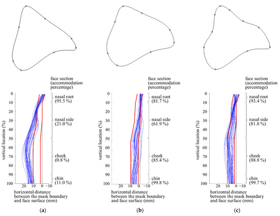
Figure 11.
Comparison of mask boundaries and accommodation percentages by face section (size: small narrow). (a) The existing mask boundary; (b) an initial mask boundary based on the representative face model; (c) the final mask boundary found by iterative design and virtual fit analysis.
The present study introduced a novel method to analyze the fit through a virtual fit simulation with 3D body scan images to find an optimal design of a product for better fit and comfort to users. Different from the previous studies on virtual fit analysis for design customization [15,21,22,23,24,25,26,27,28], this study has achieved a design optimization based on a quantitative measure such as horizontal distances between the mask boundary and the face surfaces. A placement strategy of the mask to a particular location of the face based on the information of the wearing positions of the mask over the face was introduced. The wearing positions of the mask over the faces were empirically found using measurements of the distances between the face and mask at the nose and the chin. The mask placement strategy of the present study would be preferred for a realistic virtual fit of the mask to the face to an automatic alignment method such as the iterative closest point (ICP) algorithm that can align the mask to the impractical location of the face. The proposed virtual fit analysis method using 3D body scan images would be of use to develop an ergonomic design of a wearable product for proper fit and comfort to the user population.
The photos of mask-wearing pilots, instead of 3D scans, were used in the present study due to the limited access of our research team to military facilities and the lack of portability of the 3D scanning system used in the present study. Our research team obtained approval of access to military facilities to scan KAF pilot faces, but failed to obtain approval of follow-up access to scan pilot faces worn with oxygen masks due to heightened military situations. Avoidable errors could occur in identifying mask-wearing positions due to the manual alignment of a mask CAD model and a face scan to the corresponding mask-wearing face image on the photo.
The virtual fit analysis method proposed in the present study was found effective by reducing the time and cost of prototyping and usability evaluation in the oxygen mask design process by providing the ergonomic design of oxygen mask boundary with efficiency. After preparing an oxygen mask design, a physical prototype of the mask design needs to be manufactured using an expensive molding process for usability testing under different mask operating situations (e.g., low atmospheric pressure or high gravity acceleration situation) and evaluations of other military conformity requirements (e.g., durability, toxicity, and compatibility with existing components such as microphone and valve). The design process of a pilot oxygen mask needs to avoid repetitions of prototyping, usability testing, and conformity evaluation due to limitations in research budget and development time. In the present study, the ergonomic designs of mask boundary could be found through the iterative virtual fit analysis method before prototyping. In our follow-up study, the prototype of the revised oxygen mask of the medium-wide size was fabricated first and found satisfactory to KAF pilots in terms of fit and comfort and minor design issues of the prototype (e.g., shape and thickness of flap) were reported as those to be improved; the prototypes of the other three sizes were fabricated and found satisfactory by KAF pilots [35,36].
The revised oxygen masks developed in the present study showed a better fit than the existing masks by a usability evaluation in our follow-up study [36]. The prototypes of the revised designs of four sizes were manufactured using materials similar to the existing MBU-20/P and compared to the existing designs by 88 KAF pilots in terms of discomfort, facial contact pressure, and performance. The discomfort levels of the revised masks were 33~56% lower on average than those of the existing oxygen masks. The facial contact pressure of the revised masks was 11~33% lower on average and more uniformly distributed than that of the existing oxygen masks. In a high gravity acceleration situation (e.g., 9 G), the slippage of the revised mask was 24% less on average than that of the existing masks. Figure 12 shows a visual comparison of fit between the existing MBU-20/P and revised pilot oxygen masks.
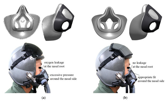
Figure 12.
Visual comparison of existing and revised pilot oxygen masks. (a) MBU-20/P oxygen mask; (b) revised oxygen mask.
The proposed virtual fit method showed significant applicability to the design of an oxygen mask for a particular user population because the proposed method considers the morphological features of the target users using a large number of 3D face scan images through the simulation process. The proposed method would develop the ergonomic design of an oxygen mask for a target user population having particular face characteristics in size and shape.
The iterative process using the virtual fit analysis method for optimization of the pilot oxygen mask design can be automated in future research for efficient application. In the present study, the mask boundary shape was manually adjusted using a CAD soft-ware program by referring to the results of the virtual fit analysis in the iterative design process. However, the iterative design process to search for a more appropriate design of the mask boundary can be automated by an algorithm maximizing the accommodation percentage in terms of the fit between mask boundary and face surfaces. The automated process would be applicable to ergonomic designs of industrial and medical masks and other wearable products to the face.
Lastly, the analyses of facial contact pressure and deformation in mask design can be incorporated into the virtual fit analysis method in future research. Although the virtual fit analysis method can help designers find an ergonomic shape of oxygen mask for various faces, the issues of contact pressure and soft-tissue deformation while wearing a mask were not considered in the present study. The distances between the mask boundary and 3D face surfaces and the results of the virtual fit analysis can be used for finite element (FE) analysis as illustrated in Figure 13 to estimate the facial contact pressure and deformation while wearing an oxygen mask as demonstrated in previous studies [29,30,37]. The FE analysis process of the oxygen mask design with multiple faces through a simulation using MATLAB programming would be conducted as a follow-up study [21,38]. By incorporating the material properties of the facial tissue and oxygen mask in the FE analysis, an appropriate mask design can be found in terms of contact pressure. The effectiveness and applicability of the proposed virtual fit method need to be further explored in comparison with the FE analysis method.
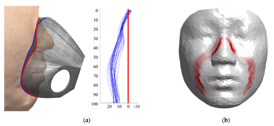
Figure 13.
Finite element analysis for the estimation of contract pressure and deformation using the horizontal distance information identified by the proposed virtual fit analysis method (illustrated). (a) Virtual fit analysis result; (b) finite element analysis result.
5. Conclusions
The present study proposed a virtual fit analysis method for designing an ergonomic oxygen mask design for a particular user population. The proposed virtual fit method consists of the analysis of the 3D facial characteristics of a user population, definition of face landmarks and mask design landmarks, identification of mask-wearing positions on the face, formation of a mask boundary shape, calculation of horizontal distances between the mask boundary and face surfaces, and iterative adjustment of the mask boundary shape for maximum accommodation percentage. The application of the proposed virtual fit method to development of revised oxygen mask designs for KAF pilots found that the accommodation percentages of the revised mask boundaries for the four sizing categories (SN, MN, MW, and LW) increased by 4.8~88.7% compared to those of the existing boundary shapes over nasal root, nasal side, cheek, and chin sections for KAF pilots. The present study supports a virtual fit approach in developing an ergonomically optimized design because an iterative process of adjustment of a product design and checking of its appropriateness to a large number of users using 3D body scans, not human participants, is possible with reasonable time and cost.
Author Contributions
Conceptualization, all coauthors; methodology, W.L. and H.Y.; software, W.L.; validation, W.L., D.J. and H.K.; formal analysis, W.L.; resources, all coauthors; writing—original draft preparation, W.L.; writing—review and editing, all coauthors; visualization, W.L. and H.Y.; supervision, H.Y. and S.P.; project administration, H.Y.; funding acquisition, H.Y. and S.P. All authors have read and agreed to the published version of the manuscript.
Funding
This research was jointly supported by the Air Force Logistics Command of the Republic of Korea Air Force, the National Research Foundation of Korea (NRF) funded by the Korea government (2018R1C1B5047805, 2020R1F1A1050076, 2018R1A2A2A05023299, 2018K1A3A1A20026539, and 2020M3C1B6113677), the Ministry of Trade, Industry, and Energy (MOTIE) under Industrial Technology Innovation Program (R0004840, 2020), and the Biomedical Research Institute Fund, Chonbuk National University Hospital.
Institutional Review Board Statement
An ethical review was not required to this study because the Korean regulations had required an IRB approval to only biomedical research until Jan. 2013 and this study was conducted from Nov. 2011 to Oct. 2012. Effective as of Feb. 2013, an IRB approval has become mandatory in South Korea to any biomedical and behavioral studies including human and animal subjects although risk involved is expected to be minimal.
Informed Consent Statement
Informed consent was obtained from all participants in the study.
Conflicts of Interest
The authors declare no conflict of interest.
References
- Lee, W.; Jeong, J.; Park, J.; Jeon, E.; Kim, H.; Jung, D.; Park, S.; You, H. Analysis of the facial measurements of Korean Air Force pilots for oxygen mask design. Ergonomics 2013, 56, 1451–1464. [Google Scholar] [CrossRef]
- Alexander, M.; McConville, J.T.; Tebbetts, I. Anthropometric Sizing, Fit-Testing, and Evaluation of the MBU-12/P Oral-Nasal Oxygen Mask; AMRL-TR-79-44; Aerospace Medical Research Laboratory: Wright-Patterson Air Force Base, OH, USA, 1979. [Google Scholar]
- Schreinemakers, J.R.C.; Westers, P.; van Amerongen, P.; Kon, M. Oxygen mask related nasal integument and osteocartilagenous disorders in F-16 fighter pilots. PLoS ONE 2013, 8, e56251. [Google Scholar] [CrossRef] [PubMed]
- Liau, Y.H.; Bhattacharya, A.; Ayer, H.; Miller, C. Determinations of critical anthropometric parameters for design of respirators. Am. Ind. Hyg. Assoc. J. 1982, 43, 897–899. [Google Scholar] [CrossRef] [PubMed]
- Gross, S.F.; Horstman, S.W. Half-mask respirator selection for a mixed worker group. Appl. Occup. Environ. Hyg. 1990, 5, 229–235. [Google Scholar] [CrossRef]
- Oestenstad, R.K.; Perkins, L.L. An assessment of critical anthropometric dimensions for predicting the fit of a half-mask respirator. Am. Ind. Hyg. Assoc. J. 1992, 53, 639–644. [Google Scholar] [CrossRef]
- Brazile, W.J.; Buchan, R.M.; Sandfort, D.R.; Melvin, W.; Johnson, J.A.; Charney, M. Respirator fit and facial dimensions of two minority groups. Appl. Occup. Environ. Hyg. 1998, 13, 233–237. [Google Scholar] [CrossRef]
- Han, D.-H.; Choi, K.-L. Facial dimensions and predictors of fit for half-mask respirators in Koreans. Am. Ind. Hyg. Assoc. J. 2003, 64, 815–822. [Google Scholar] [CrossRef]
- Zhuang, Z.; Coffey, C.C.; Ann, R.B. The effects of subject characteristics and respirator features on respirator fit. J. Occup. Environ. Hyg. 2005, 2, 641–649. [Google Scholar] [CrossRef] [PubMed]
- Oestenstad, R.K.; Dillion, H.K.; Perkins, L.L. Distribution of faceseal leak sites on a half-mask respirator and their association with facial dimensions. Am. Ind. Hyg. Assoc. J. 1990, 51, 285–290. [Google Scholar] [CrossRef] [PubMed]
- Yatapanage, K.G.; Post, K. Measurement of 3-D facial contours for the design of half-face respirators. Am. Ind. Hyg. Assoc. J. 1992, 53, 19–26. [Google Scholar] [CrossRef] [PubMed]
- Zhuang, Z.; Slice, D.E.; Benson, S.; Lynch, S.; Viscusi, D.J. Shape analysis of 3D head scan data for U.S. respirator users. Eurasip J. Adv. Signal Process. 2010, 248954. [Google Scholar] [CrossRef]
- Zhuang, Z.; Benson, S.; Viscusi, D. Digital 3-D headforms with facial features representative of the current US workforce. Ergonomics 2010, 53, 661–671. [Google Scholar] [CrossRef] [PubMed]
- Han, D.; Rhi, J.; Lee, J. Development of prototypes of half-mask facepieces for Koreans using the 3D digitizing design method: A pilot study. Ann. Occup. Hyg. 2004, 48, 707–714. [Google Scholar] [CrossRef] [PubMed][Green Version]
- Gross, M.E.; Taylor, S.E.; Mountjoy, D.N.; Hoffmeister, J. Antropometric Research on the Sizing of the MBU-20/P; AFRL-HE-WP-TR-2002-0181; Human Effectiveness Directorate, Crew System Interface Division: Wright-Patterson Air Force Base, OH, USA, 1997. [Google Scholar]
- Yang, L.; Shen, H.G.; Wu, G. Racial differences in respirator fit testing: A pilot study of whether American fit panels are representative of Chinese faces. Ann. Occup. Hyg. 2007, 51, 415–421. [Google Scholar] [CrossRef][Green Version]
- Geisen, E.; Bergstrom, J.R. Usability Testing for Survey Research; Morgan Kaufmann Publisher, an imprint of Elservier: Cambridge, MA, USA, 2017; p. xix. 230p. [Google Scholar]
- Bastien, J.M.C. Usability testing: A review of some methodological and technical aspects of the method. Int. J. Med. Inform. 2010, 79, e18–e23. [Google Scholar] [CrossRef] [PubMed]
- Mukherjee, A.; O’Kelly, E.; Arora, A.; Pirog, S.; Ward, J.; Clarkson, P.J. Comparing the fit of N95, KN95, surgical, and cloth face masks and assessing the accuracy of fit checking. PLoS ONE 2021, 16. [Google Scholar] [CrossRef]
- Lee, W.; Yang, X.; Jung, H.; You, H.; Goto, L.; Molenbroek, J.F.M.; Goossens, R.H.M. Application of massive 3D head and facial scan datasets in ergonomic head-product design. Int. J. Digit. Hum. 2016, 1, 344–360. [Google Scholar] [CrossRef]
- Lee, W.; Kim, J.-G.; Molenbroek, J.M.F.; Goossens, R.H.M.; You, H. Estimation of facial contact pressure based on finite element analysis. In Advances in Additive Manufacturing, Modeling Systems and 3D Prototyping; Advances in Intelligent Systems and Computing; Springer: Cham, Switzerland, 2020; pp. 657–667. [Google Scholar]
- Apeagyei, P.R. Application of 3D body scanning technology to human measurement for clothing Fit. Int. J. Digit. Content Technol. Its Appl. 2010, 4, 58–68. [Google Scholar] [CrossRef]
- Guan, P.; Reiss, L.; Hirshberg, D.A.; Weiss, A.; Black, M.J. DRAPE: DRessing Any PErson. ACM Trans. Graph. 2012, 31, 1–35. [Google Scholar] [CrossRef]
- Lee, Y.; Ma, J.; Choi, S. Automatic pose-independent 3D garment fitting. Comput. Graph. 2013, 37, 911–922. [Google Scholar] [CrossRef]
- Pons-Moll, G.; Pujades, S.; Hu, S.; Black, M.J. ClothCap. Acm Trans. Graph. 2017, 36, 1–15. [Google Scholar] [CrossRef]
- Ellena, T.; Subic, A.; Mustafa, H.; Pang, T.Y. The Helmet Fit Index—An intelligent tool for fit assessment and design customisation. Appl. Ergon. 2016, 55, 194–207. [Google Scholar] [CrossRef] [PubMed]
- Alemany, S.; Olaso, J.; Nacher, B.; Gil, M.; Hernandez, A.; Piza, M.; Solves, C. A multidimensional approach to the generation of helmets’ design criteria: A preliminar study. Work 2012, 41 (Suppl. 1), 4031–4037. [Google Scholar] [CrossRef]
- Lei, Z.P.; Yang, J.; Zhuang, Z.Q. A Novel Algorithm for Determining Contact Area Between a Respirator and a Headform. J. Occup. Environ. Hyg. 2014, 11, 227–237. [Google Scholar] [CrossRef] [PubMed][Green Version]
- Dai, J.C.; Yang, J.Z.; Zhuang, Z.Q. Sensitivity analysis of important parameters affecting contact pressure between a respirator and a headform. Int. J. Ind. Ergon. 2011, 41, 268–279. [Google Scholar] [CrossRef]
- Lei, Z.; Yang, J.; Zhuang, Z. Headform and N95 filtering facepiece respirator interaction: Contact pressure simulation and validation. J. Occup. Environ. Hyg. 2012, 9, 46–58. [Google Scholar] [CrossRef]
- Lee, W.; Kim, H.; Jung, D.; Park, S.; You, H. Ergonomic design and evaluation of a pilot oxygen mask. In Proceedings of the Human Factors and Ergonomics Society 57th Annual Meeting, San Diego, CA, USA, 30 September–4 October 2013. [Google Scholar]
- Jung, H.; Mun, S.; Lee, W.; You, H. Measurement of the Internal Shape of Power Grip in Wrist Ulnar/Radial Deviation. Proc. Hum. Factors Ergon. Soc. Annu. Meet. 2019, 63, 1149–1153. [Google Scholar] [CrossRef]
- Lee, W.; Lee, B.; Kim, S.; Jung, H.; Bok, I.; Kim, C.; Kwon, O.; Choi, T.; You, H. Development of headforms and an anthropometric sizing analysis system for head-related product designs. In Proceedings of the Human Factors and Ergonomics Society 59th Annual Meeting, Los Angeles, CA, USA, 27–31 October 2015. [Google Scholar]
- Lee, B.; Jung, K.; You, H. Development of a distributed representative human model (DRHM) generation and analysis system for multiple-size product design. In Proceedings of the Human Factors and Ergonomics Society 57th Annual Meeting, San Diego, CA, USA, 30 September–4 October 2013. [Google Scholar]
- Lee, W. Development of a Design Methodology of Pilot Oxygen Mask Using 3D Facial Scan Data; Pohang University of Science and Technology: Pohang, Korea, 2013. [Google Scholar]
- Lee, W.; Yang, X.; Jung, D.; Park, S.; Kim, H.; You, H. Ergonomic evaluation of pilot oxygen mask designs. Appl. Ergon. 2018, 67, 133–141. [Google Scholar] [CrossRef]
- Lei, Z.; Yang, J.; Zhuang, Z.; Roberge, R. Simulation and evaluation of respirator faceseal leaks using computational fluid dynamics and infrared imaging. Ann. Occup. Hyg. 2013, 57, 493–506. [Google Scholar] [CrossRef]
- Lee, W.; Molenbroek, J.F.M.; Goto, L.; Jellema, A.H.; Song, Y.; Goossens, R.H.M. Application of 3D scanning in design education. In DHM and Posturography; Scataglini, S., Paul, G., Eds.; Academic Press: Cambridge, MA, USA, 2019. [Google Scholar]
Publisher’s Note: MDPI stays neutral with regard to jurisdictional claims in published maps and institutional affiliations. |
© 2021 by the authors. Licensee MDPI, Basel, Switzerland. This article is an open access article distributed under the terms and conditions of the Creative Commons Attribution (CC BY) license (https://creativecommons.org/licenses/by/4.0/).