Abstract
Matrix converters have been extensively investigated in academia over the last 3 decades. Several review works targeting matrix converter topologies, commutation strategies, modulation and control techniques have been published. However, to the best of the authors’ knowledge, a review on the potential contributions of matrix converters for applications that are shaping the electric power sector transition towards decarbonization is lacking, namely applications on smart grids, sustainable transportation and electrical drives. This paper presents an extensive literature review on the more relevant research works targeting applications of matrix converters as an enabling key technology for smart and resilient grids, sustainable transportation, and innovation in variable speed electric drives.
1. Introduction
Matrix converters are single-stage alternating current (AC/AC) power converters mainly based on power transistors with minimal passive component requirements. Since their appearance, matrix converters have been a topic of research with extensive study in topological variations, control methods/strategies, reliability and loss analysis [1].
Even though the industrial applications of matrix converters have been somewhat limited by constraints such as efficiency and semiconductor drive requirements, recent developments in semiconductor technologies combined with more affordable and powerful computation devices, such as system-on-chip technologies that combine both Field-Programmable Gate Array (FPGA) and microprocessors inside the same chip enabling the use of more complex control schemes, shape a promising future for matrix converters in a variety of applications.
Matrix converters are bidirectional power topologies that allow AC/AC power conversion, without intermediate energy storage, revealing one of the most important advantages of matrix converters when compared to traditional back to back (B2B) voltage source converters (VSCs). Furthermore, the reduced filtering requirements makes the matrix converter a topology mainly dependent on power semiconductors, and as a direct consequence the matrix converter is able to achieve unparalleled power densities, an attractive feature for applications such as aerospace, aeronautics, military, electrical traction and distribution in high price real estate areas.
To allow bidirectional operation, matrix converters are constructed with bidirectional power semiconductor switches. Each bidirectional switch can be operated in the four-quadrants and controlled at a frequency much higher than the output or input fundamental frequencies , . With the use of recent power semiconductor technologies, such switches can be attained in a variety of configurations with different semiconductor technologies. Figure 1 shows different configurations of semiconductors for controlled 4-quadrant bidirectional switches. The most common configurations are both the common emitter and the common collector insulated gate bipolar transistor (IGBTs) configurations with their respective antiparallel diodes (Figure 1a,b). With the current trends on wideband-gap technologies the use of silicon carbide metal oxide semiconductor field effect transistors (SiC MOSFETs) (Figure 1c,d) allows for increased efficiencies and higher switching frequencies than the switches with silicon IGBTs. Reverse blocking IGBTs (RB-IGBTs) (Figure 1e) have also been employed in matrix converter applications in an effort to increase the converter efficiency by reducing the switch conduction losses [2,3].
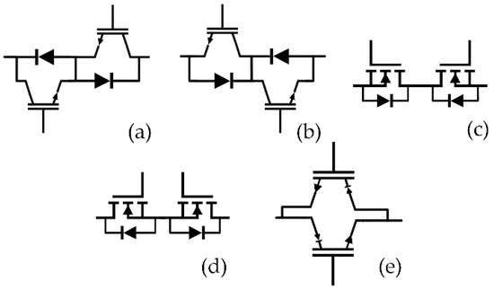
Figure 1.
Common configurations for 4-quadrant bi-directional switches: (a) common emitter insulated gate bipolar transistors (IGBTs), (b) common collector IGBTs, (c) common drain N-channel metal oxide semiconductor field effect transistors (MOSFETs), (d) common source N-channel MOSFETs, (e) anti-parallel reverse blocking IGBTs.
Matrix converters can be divided into two different families of converters, single-stage or direct matrix converters (DMCs) and dual-stage or indirect matrix converters (IMC). Several topology variations within these two categories exist and their analysis and labeling have been extensively covered across different works [4]. Simplified structures depicting the most common topologies for DMCs and IMCs can be found in Figure 2a,b, respectively, while a common topology for a single phase matrix converter is shown in Figure 2c. Each family of topologies has their benefits and drawbacks and the appropriate selection will depend on each specific application requirements.
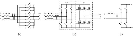
Figure 2.
Schemes for two matrix converter topologies families. (a) Direct/one stage matrix converter (b) indirect/dual stage matrix converters. (c) Single-phase matrix converter.
Despite the listed advantages, matrix converters output/input voltage ratio is lower than one, meaning the output voltages are always lower than the input voltages. This limitation is more relevant for variable speed electrical drives, as it will result in the limitation of the electrical machine’s mechanical speed. This issue is further addressed in section five.
However, in grid connected systems that make use of power transformers, this issue can be simply mitigated using a transformer with suitable turns ratio. Also, in some applications such as in photovoltaic (PV) systems where the preferential current path is from an energy source to the grid, the matrix converter actually behaves as a boost converter which can bring advantages that are further explored in section four.
Throughout this work the use of matrix converters in the conversion of AC/DC (direct current) or DC/AC is referred hereafter as a current source rectifier (CSR) when the preferential power flow is from the grid to the load and as a current source inverter (CSI) when the preferential power flow is from an energy source to the grid.
The numerous contributions and developments of AC/AC matrix converters have significantly increased the technology maturity to a point where in a near future matrix converters can find their way to a wide number of applications, including AC/DC and DC/AC conversion. This change of paradigm motivated this review with the purpose to show research work on matrix converters operating as AC/AC, as AC/DC, or DC/AC, with practical application in the development of new smart-grid assets, sustainable transportation, renewable energy increased grid penetration, and innovations in electrical drives. The literature review took into consideration scientific articles with preference, but not limited to Q1 journals and renowned conferences with the search being conducted through IEEE Xplore and Google Scholar.
This paper is divided into 7 sections, each providing special emphasis on tackling challenges of matrix converters in relevant future industry applications of power converters:
- The first section briefly introduces practical considerations on the design of matrix converter-based topologies with a special care given to the bidirectional switches commutation methods.
- The second section focuses in “Enabling technologies for smart and resilient grids”, presenting matrix converter applications towards a smarter, more efficient, versatile and sustainable grid.
- The third section presents prominent applications of matrix converters in the connection of renewable energies to the grid, a crucial topic with the increasing demand for decarburization.
- The fourth section highlights how matrix converter-based topologies tackle challenges in future variable speed electric drives, whose impact spreads across almost all industrial fields
- Electric mobility promises the electrification of most transportation vehicles, and the interface between the grid and electric vehicles is the topic of the fifth section highlighting the contributions of matrix converters.
- The sixth section covers potential contributions of matrix converters to the pursuit of more sustainable transportation means detailing work developed on electric aircraft, marine and traction applications.
- The final section introduces future challenges and research needs for matrix converters whose development is crucial for the penetration of the matrix converter in the aforementioned applications.
2. Practical Considerations on the Implementation of Matrix Converters
Being an “all silicon” topology with bidirectional switches, matrix converters require dedicated commutation schemes that go beyond the simple use of “dead-times” or overlapping the semiconductors driving signals. Furthermore, unlike typical VSCs, in matrix converters there are no natural freewheeling paths for the output currents. Opening such currents when using inductive loads will result in high transient overvoltages that ultimately can damage the semiconductors or the load.
The commutation strategy can be undertaken in either two steps or four steps and can either be based on the output load currents or the input phase to phase voltages [1]. On four-step based commutation methods, both devices in the current path of the conducting bidirectional switch are enabled during the normal conducting stage, while on two step-based method only the devices that match the direction of the load current are enabled. The advantage of two-step methods is that they require fewer commutations of semiconductors than the four-step methods. However, depending on the type of bidirectional switch used it might be beneficial to keep both semiconductors enabled. For example, when using MOSFET and junction field effect transistors (JFET) semiconductors that allow source to drain currents when the channel is active, a four-step method might result in lower conduction losses.
Figure 3 represents the application of the current-based four-step commutation method when switching from the bidirectional switch S1 to the bidirectional switch S2 with a positive output current. Step 1, represented in Figure 3a, initiates the commutation process by opening the non-conducting semiconductor of the conducting switch (S1 in the depicted case). Step 2, represented in Figure 3b, closes the semiconductor that will conduct the output current of the future conducting switch (S2 in the depicted case), which semiconductor of the switch is closed in this step depends on the signal of the output current of that particular phase. Step 3, represented in Figure 3c, fully opens the previously conducting bidirectional switch. This can be done since a new path for the output current was created in Step 2. Finally Step 4, represented in Figure 3d, closes the non-conducting semiconductor of the new conducting bidirectional switch (S2) finalizing the commutation process.
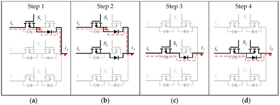
Figure 3.
Representation of a current based four-step commutation method switching from bidirectional switch S1 to bidirectional switch S2. The different commutation steps are represented: (a) Step 1, (b) Step 2, (c) Step 3 and(d) Step 4.
The voltage-based techniques are very similar but instead of using the measurement of the output current to select the conducting and non-conducting switches they use the measurement of the input phase to phase voltage and select the sequence ensuring that no short circuits happen.
The two step techniques as stated above use only Steps 2 and 3 of the four step commutation methods keeping only one semiconductor closed per switch.
Typically, due to timing requirements for the commutation steps, FPGAs are used to handle these commutation schemes. Besides the implementation of each step and the selection of the appropriate timings, it is important to latch both the measurement signals input and the new conducting switches’ signal input so that these signals do not change during the commutation period, which otherwise could lead to open circuits on the output, or input short circuits.
Along with this work, a base implementation in VHDL of a current-based four step commutation method is provided so that it can facilitate the process of implementing matrix converters, that can be found https://github.com/pccosta/MatrixConverter4StepCommutation (accessed on 18 May 2021).
Another typical concern when designing matrix converters is the protection circuit. In the particular case of direct matrix converters if there is a switch malfunction and an inductive load current path is suddenly interrupted, it may result in overvoltages. Several techniques have been proposed to address this problem. The most usual is the use of a clamper, consisting of a set of two diode rectifiers, one connected to the matrix converter input phases while the second is connected to the matrix converter output phases, featuring a common DC link capacitor to mitigate the transient overvoltages. Another solution is the use of input and output varistors. Also, the use of dedicated semiconductor firing sequences can ultimately lead the converter to a safe state, for example, a vector leading to zero output voltage or a different modulation strategy [5,6,7].
3. Enabling Technologies for Smart and Resilient Grids
Smart grids (SGs) aim at using digital technology to increase the grid controllability, efficiency and reliability. Empowering the grid with modern telecommunication infrastructures and power converters enables the necessary grid resilience for a heavily distributed energy production which is the major key to fully maximize the penetration of renewable energies given their decentralized nature. Furthermore, increasing distributed energy systems will result in a grid dominated by inverters creating even more challenges for the grid such as stability, inertia, short circuit protections [8,9,10], reactive power control and coordination between different controllers for different types of distributed generation unit [11,12]. This raises power quality (PQ) concerns that may require short term energy storage systems as in [13], where a flywheel and a 3 × 3 direct matrix converter using a predictive optimal controller are proposed to compensate voltage sags and swells while minimizing the voltage total harmonic distortion (THD).
The need to overcome these challenges has motivated research on the topic of smart transformers [14,15] since conventional distribution transformers were mainly designed for unidirectional power flow with little to no control capabilities over the grid parameters. Power electronics can enable increased functionalities in the conventional transformers. Possible solutions can go from a combined system with a low-frequency transformer aided by power electronic converters (hybrid transformer) to the full replacement of the low-frequency transformer by solid state transformers (SST).
The application of matrix converters is here divided into hybrid transformers, SSTs and flexible AC transmission systems (FACTS).
3.1. Matrix Converter Applications in Hybrid Transformers
Hybrid transformers enable AC voltage regulation in distribution grids. Traditionally, this regulation could be done with tap changers in conventional transformers [16], with poor dynamic response and a narrow adjustment range. matrix converters can empower traditional distribution transformers with AC voltage compensation with fast dynamic response in the mitigation of voltage sags and swells.
The advantages of a 3 × 3 direct matrix converter based dynamic voltage restorer (DVR) as well as a suited modulation for sag and swell compensation is presented in [17]. A DVR also without storage devices with an indirect 3 × 3 matrix converter is proposed in [18], capable of compensating balanced and unbalanced voltage sags and swells. A hybrid transformer with a 3 × 3 direct matrix converter that can work as a DVR and additionally control the power flow by means of phase shifting is proposed in [19,20] providing both simulation and experimental results. A similar proposal for an active distribution transformer that is also able to perform the function of a DVR with the ability to mitigate sags and swells up to 20% together with power flow control is proposed in [21] where a sliding mode controller is used to guarantee the tracking of the input and output currents. The topology for this work is presented in Figure 4 serving as an example of the application of matrix converters in hybrid transformers. Finally a comprehensive comparison for DVRs using matrix converters is given in [22].
Figure 4.
Example of a matrix converter-based hybrid transformer, adapted from [21].
To highlight the matrix converter capabilities in hybrid transformer applications, experimental results are shown in Figure 5 for a voltage sag compensation and local power factor compensation using the topology from Figure 4.
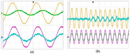
Figure 5.
Experimental results of matrix converter-based hybrid transformer (a) local power factor compensation, LV voltage and current (purple and blue respectively), MV voltage and current (yellow and green respectively). (b) Voltage sag compensation, LV voltage and current (purple and green respectively), MV voltage and current (yellow and blue respectively).
The presented results demonstrate the application of the matrix converter in relevant future challenges of the electrical grid where both disturbance mitigation and active power quality contributions are of major importance.
3.2. Matrix Converter Applications in Solid State Transformers (SSTs)
Solid state transformers (SSTs) are receiving increasing focus in academia with a number of distinct topologies and concepts emerging in recent years [23]. The use of high/medium frequency transformers enables new paradigms for power density and functionality of these devices. A different range of applications can benefit from the use of SSTs, from smart grids [24] to traction [25], aviation and naval applications [26].
Figure 6 shows typical SST topologies in the replacement of conventional distribution transformers from medium voltage to low voltage.
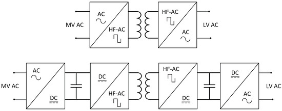
Figure 6.
Representation of a two-stage and a four-stage solid state transformers (SST) topology using medium to high frequency transformers.
Applications in SGs can also be found in [27], where a grid forming SST with modular matrix converters and a medium frequency transformer operating in the 2 kHz range is proposed. The authors highlight the capability of voltage sag and swell mitigations and propose a modified space vector modulation that prevents the saturation of the transformer.
In [28] a three-phase modular isolated matrix converter is proposed, where single phase matrix converters are coupled with medium frequency transformers operating in the range of 5 to 10 kHz, using suitable modulation and control strategies. The same authors also approach in [29] the problem of switching between the converter vectors under the effect of the leakage inductance of the transformer proposing a suitable commutation strategy.
A solid state transformer using an indirect matrix converter-based topology is proposed in [30] where the authors devise a model predictive controller (MPC)-based controller with the aim of allowing a bidirectional power flow and mitigating power quality issues. However, the proposed topology is only suitable for LV to LV applications given the lack of modularity of the proposed topology.
In [31] a matrix converter is used as a LV output stage of a SST where the input is composed of back to back VSCs. A modulation technique and a controller are proposed such that the output of the SST enables voltage swell and sag mitigation together with input power factor correction.
To highlight potential modular topologies that employ matrix converters in the connection to the MV grid, two different topologies are displayed.
The first one, in Figure 7, shows a SST topology proposed in [23] where a 3 × 3 direct matrix converter is coupled trough a high frequency transformer to three single phase matrix converters so that it can be coupled in series at the input and in parallel at the output enabling the conversion from MV to LV.
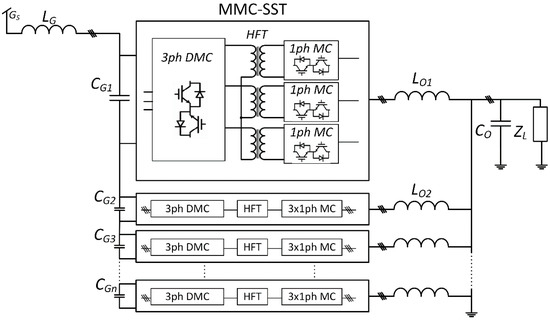
Figure 7.
Matrix converter-based SST topology as proposed by [27] with the required modularity for the conversion of MV to LV.
A second SST topology is presented in Figure 8 and can be connected to the MV grid to generate LV nanogrids for both AC and DC power distribution networks as highlighted in [32]. A single-phase matrix converter is used to convert high AC voltages to low DC voltages by means of current doubler rectifiers (CDRs). The output of these CDRs can then be used to connect the AC LV bus through a VSC, or to connect DC distributed energy resources (DERs) as batteries (distributed energy storage systems—DESSs) and photovoltaics (PVs), among others.
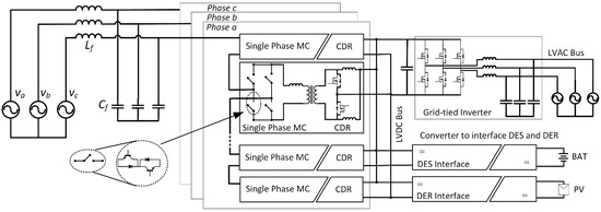
Figure 8.
Topology of a matrix-based SST for a hybrid nanogrid.
3.3. Matrix Converters Applications in Flexible Alternating Current Transmission Systems (FACTS)
FACTS have played an important role in the stability, controllability and power transfer capability of the transmission grid for more than 50 years. Most FACTS have traditionally made use of thyristors; however, with the introduction of distributed FACTS [33] and the widespread of pulse width modulation (PWM) converters in unified power flow controllers (UPFC) the use of matrix converters for such systems once again gains relevance, as no DC link with low reliability electrolytic capacitors is needed.
The development of a distributed static synchronous compensator (STATCOM) aiming for power quality improvement in the LV network can be found in [34] making use of a 3 × 3 DMC. Another STATCOM with a 3 × 3 DMC is proposed in [35] using MPC for the control of the power converter. A matrix converter-based shunt reactive power compensation device can be found in [36] where the typical STATCOM capacitors are replaced by a permanent magnet synchronous machine.
A UPFC using a 3 × 3 DMC can be found in [37] where a direct power control method is proposed and evaluated against typical proportional-integral (PI) controllers. A comparison between linear, decoupled and direct power controllers for matrix converters UPFC’s can be found in [38]. A depiction of an UPFC using a matrix converter can be seen in Figure 9 using a topology proposed by [37].
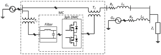
Figure 9.
Representation of a matrix converter-based unified power flow controller (UPFC) using a topology as suggested in [37].
4. Matrix Converters in the Connection of Renewable Energies to the Grid
Increasing environmental concerns have led to growing efforts in the pursue of a 100% renewable carbon-free electrical grid [39]. In order to achieve such a goal, the integration of renewable energy sources in the grid will have to continue increasing. PV and wind energy are two of the most relevant renewable energy resources. The connection of these systems to the grid demands high efficiency and reduced costs to ensure economic viability as well as a high degree of controllability that meets the demanding criteria for a resilient grid composed mostly of distributed energy resources.
With the increasing use of non-linear loads and the growing penetration of solar and wind renewable energy in smart grids, new PQ issues are arising that create challenges for distribution system operators (DSOs). These include issues such as low-order current harmonics, non-unity displacement power factor (DPF) or voltage-related disturbances at the point of common coupling (PCC). These issues can be mitigated by adding enhanced PQ compensation functionalities to the PV array converter, with shunt and/or series connection to the SG.
Although matrix converters are primary AC–AC converters, best suited for wind energy conversion systems, they can be advantageously used as DC–AC converters in Photovoltaic (PV) arrays. Figure 10 shows a potential application of a DMC in the injection of P- generated energy into the grid.
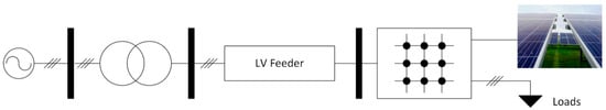
Figure 10.
Typical application of matrix converter in the integration of renewable energy to the grid.
4.1. Matrix Converter Applications for Integration of Photovoltaic (PV) Systems
This section investigates the application of matrix converters for the integration of PV arrays in SGs, and the possibilities for improving the PQ in the connection to the SG. In particular, the connection of a PV array to the SG with a unidirectional 3 × 2 matrix converter topology (shunt connection) or using an IMC (series and shunt connections) is considered.
4.1.1. Power Quality Compensation in the Connection of PV Arrays to the Smart Grid (SG)
In the connection of the PV arrays to the SG the converter should guarantee that the current harmonic limitations set by standard IEC 61000-3-2 are met [40,41], while the distribution voltage quality must comply with standards IEC 61000-3-3 and EN 50160, in terms of voltage root-mean-square (rms) value and harmonic content [42,43]. In particular, the voltage-related PQ issues such as voltage instability with voltage sags, swells or harmonics or permanent undervoltage or overvoltage are important for sensitive loads that often require a voltage supply with near constant rms value to avoid degradation and decrease in efficiency [40,42,44].
Novel converter topologies and control methods have been proposed in the literature to act as active power filters (APFs) with reduced impact on the SG. In these works, the shunt connection of the PV converter to the grid allows compensating the low-order harmonics from the non-linear loads. Voltage-related PQ issues can be compensated to a certain extent using this shunt connection, with reactive power compensation and active power limitation [45,46,47,48,49,50]. This helps avoiding the disconnection from the SG in case of severe issues, but the compensation is limited by the network impedance [45,51,52,53]. In order to allow for a proper voltage compensation at the PCC, a series connection to the SG can be added, applying a voltage in series with the grid to control the voltage that supplies the sensitive loads. These APFs are either of the CSI [54] or VSI [55] type.
4.1.2. Unidirectional 3 × 2 Matrix Converter Topology Application
The CSI topology is equivalent to an unidirectional 3 × 2 matrix converter and can be considered as such. For the connection of PV arrays to the SG, this single-stage unidirectional topology, as shown in Figure 11, has several advantages compared to the more conventional VSI and it has regained attention in the last years [56,57]; it can be noted that the input/output voltage gain of the matrix converter can be beneficial in this application since it allows to boost the PV voltage allowing more flexibility on the PVs’ configuration [58].
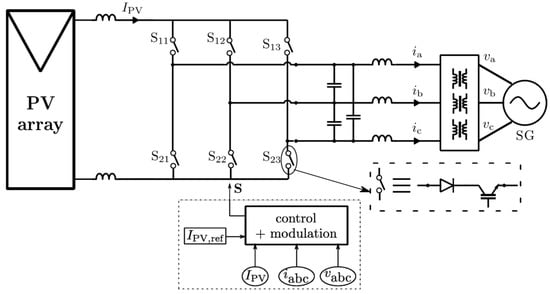
Figure 11.
Proposed grid-tied photovoltaic (PV) array with a current source inverter (CSI).
The electrolytic capacitor used in VSI topologies is widely considered to be the least reliable component in PV systems. Using the 3 × 2 matrix converter a dc link inductor is used, instead of the electrolytic capacitor, for increased robustness, reliability and longer lifetime of the PV system [57,59,60,61]. Also, a filtered DC link current is more suited to a PV system application as it reduces the stress on the PV arrays [57,59,60]. In addition, the 3 × 2 matrix converter has an inherent voltage step-up capability with a minimum admissible transfer ratio of 1.155 which increases the PV array voltage range and allows the grid voltage level to be matched without the need for extra conversion stages [58,62]. This single-stage topology improves the reliability of the system and reduces the cost and losses [59,63]. Novel configurations have been proposed in the literature to avoid earth leakage currents into the grid without using a bulky and costly isolation transformer [57,64,65].
This unidirectional 3 × 2 matrix converter topology can be used to compensate PQ issues in the connection of PV arrays to the SG with current harmonics compensation [54] and fault voltage ride-through (FVRT) capability [66]. However, the compensation capability of a shunt-connected converter is limited, therefore PV converter topologies including shunt and series connections to the SG for current and voltage compensations have been considered in the literature [67,68,69]. This leads to a unified power quality conditioner (UPQC) topology [70] where the PV array is connected to the dc link.
4.1.3. Indirect Matrix Converter Topology Application
Instead of using a single shunt converter or the most common VSIs for the shunt and series connections to the grid, it is also possible to connect the PV array to the SG using an IMC [67,71], as shown in Figure 12. The PV array is inserted on the virtual ‘dc link’ of the IMC and the system overall guarantees improved compactness and higher reliability, due to the absence of a bulky electrolytic capacitor in the dc link [72,73,74,75]. The series voltages compensate the grid voltages to supply sinusoidal voltages to the sensitive non-linear loads while the shunt converter currents compensate the load currents to absorb sinusoidal currents to the SG.
Figure 12.
Proposed grid-tied PV array with Indirect matrix converter.
In addition, the matrix converter technology offers higher power density with bidirectional power flow and high-quality input and output currents [72,76,77]. Even though it is not commonly used for general-purpose applications as it lacks the voltage-step-up capability (input/output ratio of 0.86 for sinusoidal modulation) [76] and has no internal energy storage, the topology in Figure 12 is suited to the PV array connection considering that the PV array voltage is usually lower than the grid voltage. The shunt converter, therefore, acts as a voltage-step-up CSI with a minimum transfer ratio of 1.155, which defines the maximum PV array operating voltage [54].
Due to the direct connection between the shunt and series converters, the switching vectors must be selected carefully, to avoid applying negative voltage to the ‘DC link’. Indirect space vector pulse width modulation (SV-PWM) [67] or direct sliding mode control [71] can be applied to the converters to control the voltages at the PCC and the grid currents.
4.1.4. Experimental Indirect Matrix Converter (IMC) Application Results
The SG integration of PV arrays using an IMC has been tested in the laboratory using the fast-prototyping software and hardware dSPACE 1103, with a specific attention to the switching vector transitions to avoid negative voltages on the ‘DC link’. The grid line-to-ground voltage rms value is 110 V and the sample time 18 μs.
Results are shown in Figure 13a for the shunt compensation of a 250 W non-linear load low-order harmonics. The load currents present high 5th and 7th harmonics (THD of 33%) that are compensated for by the shunt converter to reduce the SG currents THD to 10.83% with Displacement Power Factor (DPF) of 0.997. In Figure 13b the series compensation is tested with a 15% sag. The voltage at the PCC maintains a constant rms value during the sag in order to supply the sensitive loads and it is in phase with the grid voltages.
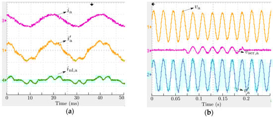
Figure 13.
Experimental results of integrating a PV array into the smart grid (SG) with indirect matrix converter (IMC) and power quality (PQ) compensation. (a) Shunt current compensation with a 250 W non-linear load: grid line current ia, shunt converter ac line current ia’ and load line current in1,a [5 A/div]. (b) Series voltage compensation with a 15% sag: grid line-to-ground voltage va, series compensation line-to-line voltage and load line-to-ground voltage va’ [125 V/div].
4.2. Matrix Converter Applications in Wind Energy Conversion Systems
The European Wind Energy Association predicts that wind energy will represent 30% of the European union electricity generation by 2030, and 50% by 2050 [78]. Indeed, the growth of installed capacity of wind energy conversion systems (WECS) in the last 2 decades determined not only on the increase in size and rated power of individual WECS but also changed the role that such systems represent to the grid. Nowadays WECS act as active contributors and stabilizers to the electrical grid by providing support on the grid frequency stabilization and voltage regulation providing fault ride through (FRT) capability [78].
Currently, the majority of WECS are based on wind turbines coupled through a gearbox to a dual-fed induction generator (DFIG) with its stator connected to the grid while its rotor is supplied by a B2B converter, as shown in Figure 14a [79]. This topology allows the power converter to process only about one third of the power delivered to the grid but relies on bulky and failure-prone electrolytic DC-link capacitors. A DMC-based alternative to this B2B is given in Figure 14b.
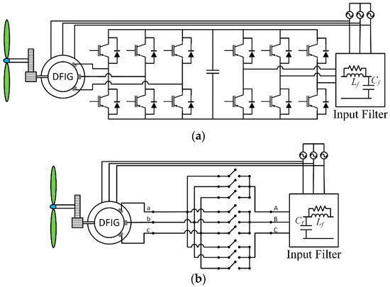
Figure 14.
Wind energy conversion systems (WECS) based on dual-fed induction generator (DFIG). (a) Typical wind energy conversion systems (WECS) based on back to back (B2B) converter. (b) Direct matrix converter (DMC) alternative to B2B for WECS.
The replacement of the B2B by matrix converter-based topologies for Induction Generators based WECS has been approached in the literature. In [80] a grid connected WECS based on a squirrel cage Induction generator fed by a DMC is analyzed with special care given to stability issues related to the design of the filter and its damping coefficient for the whole WECS power and speed range. The authors of [81] proposed an improved direct torque control (DTC) scheme with grid reactive power control capability for a DMC-fed DFIG WECS. The researchers in [82] introduced a method for finding the DFIG optimum stator reactive power reference in order to maximize the active power injected to the grid at a given wind speed and grid power factor. They also derived the active and reactive power diagrams for DMC-fed DFIG WECS. In [83] a model-based predictive rotor current controller for an IMC fed DFIG WECS is implemented achieving a fast dynamic response.
WECS gearboxes and its bearings are among the major causes of WECS downtime [84]. Among electrical machines universe, DFIGs are expected to require a high level of maintenance due to the brushes that allow the supply of its rotor windings. For these reasons, there is a growing interest in direct drive WECS based on permanent magnet generators (PMGs) with high number of poles, resulting in gearless and brushless WECS [85].
This concept is further developed in [86] by supplying the PMG through a DMC. The authors introduce a control methodology that allows power factor variation on the machine side to improve the grid-side maximum achievable power factor regulation for the entire rated range of the WECS speed and power.
The high number of poles required due to the low and small speed range of PMG in gearless WECS may result in wider machines with lower voltage ratings. In [87] the authors analyze two variants of ultrasparse matrix-based topologies that feature a Z-source network as an intermediate stage for voltage boost from the PMG side to the grid, presented in Figure 15a,b. Even though the analyzed converters only allow unidirectional power flow capability, not allowing WECS start, the bidirectional power flow would be obtainable by converting the ultrasparse matrix input stage to a sparse-matrix one.
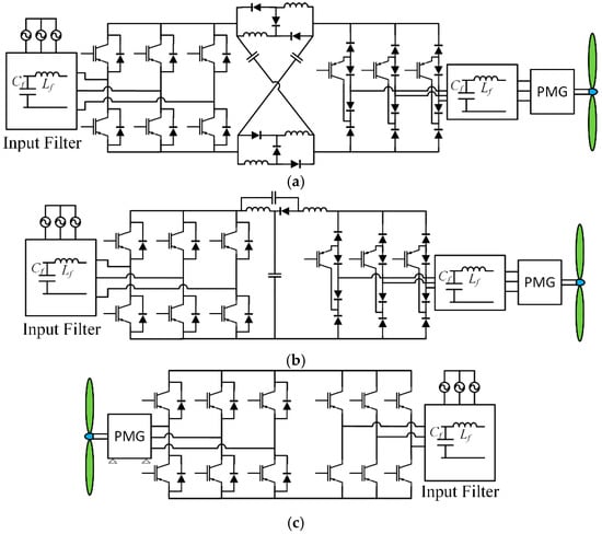
Figure 15.
IMC based topologies with voltage boosting capability. (a) Switched-inductor Z-source matrix converter. (b) Quasi-Z-source matrix converter. (c) Zero-link impedance direct drive wind turbine topology proposed by [88].
Another boost topology based on variations of the traditional IMC is presented in [88], shown in Figure 15c where special care was given to the advantages that come with the use of a low voltage with lower number of poles PMG. The authors report significant improvements in the size, weight, power density and torque ripple of the proposed PMG.
4.3. Matrix Converter Application for the Connection of Offshore Wind Farms to the Grid
Offshore wind farms will constitute a significant part of future renewable power plants. Bigger and more powerful WECS are required to reduce the life cycle cost of these technologies due to the higher cost of installation, operation and maintenance because of challenging weather conditions, operator transportation and material shipment from the mainland to offshore wind parks [78].
A fully modular configuration based on the M3C topology, as depicted in Figure 16a, is analyzed in [89], featuring high scalability potential and easy redundancy integration. The proposed control approach is detailed and the WECS operation under different scenarios including operation under FRT is provided.
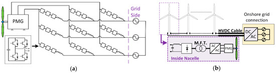
Figure 16.
Matrix converters applications for offshore wind farms. (a) fully modular architecture based on M3C topology. (b) Redesigned offshore wind farm architecture featuring a medium frequency transformer.
The transmission distance from offshore wind farms to mainland brought new ideas on how the traditional windfarm can be redesigned. An HVDC connection from the coast to the offshore windfarm where the WECS are all connected in series, as shown in Figure 16b, is proposed in [90]. A study of six different topologies featuring a Medium Frequency Transformer (MFT) is presented comparing three B2B converter based topologies and three matrix converter based topologies (DMC, IMC, CSI). Although the analysis was carried out for an ac-link frequency in the range of 500 Hz to 20 kHz, considering only one MFT core material, not allowing generalization for other magnetic materials, the CSI topology was clearly the preferred choice due to its lower volume and higher efficiency for ac-link frequencies above 3 kHz.
A technology that has gained some attention for possible application on offshore windfarms transmission lines is the low-frequency alternating current (LFAC). By reducing the frequency bellow 50 Hz on the transmission line, its capability of transmitting power without increasing the voltage level is improved. A study of a M3C converter-based LFAC transmission system and its control strategy is presented in [91].
5. Matrix Converters Contribution towards the Innovation of Electrical Drives
Traditionally, electric drives are composed by two distinct sub-assembles: the electric machine and its corresponding controlled power converter. Over the last decades there has been a shift from these physically separated systems to more compact, efficient and robust drives [92,93]. The future trend is to achieve a fully integrated and smart machine that consists in a single plug and play drive.
The integration of power electronic converters and controller modules inside electrical machines brings challenges due to size constrains and thermal management issues. Currently, typical power converters for electric drives require a relatively high volume of passive components such as inductors and capacitors. The challenges are more strict on the DC link capacitors, that in most cases are electrolytic capacitors, whose lifetime is substantially reduced under high temperature operation as usually found inside electrical machines, greatly compromising the drive lifespan [92].
The search for drives with improved performance and fault tolerance contributed to the rise in popularity of multiphase machine drives (more than 3 phases) and open-end winding (OEW) configurations [94]. While all these configurations improve the drive fault tolerance, multiphase machines are normally characterized by allowing torque ripple reduction while achieving higher power density and efficiency than traditional drives [95,96]. OEW configurations can improve input to output voltage ratio utilization increasing the drive speed range [97], while allowing multilevel operation and the ability to eliminate common mode voltage (CMV) that is pointed to as the major cause for premature fails of converter supplied electric machines [98].
In this section, matrix converter topologies and modulation schemes for multiphase and OEW machine applications are presented.
5.1. Direct Matrix Converter (DMC)-Based Works
The higher number of phases or actively driving both ends of the machine windings increase the switch count but results in additional available switching states. From one perspective those extra switching states offer more control flexibility, but on the other hand the modulation complexity is increased. This might be the reason for the extensive research work on modulation techniques for such configurations.
In [99] a space vector modulation (SVM) technique for OEW 3 × 3 DMCs (3 input phases and 3 output phases) is proposed making only use of rotating space vectors, which are divided into a group rotating in the clockwise (CW) direction and other rotating in the counter-clockwise (CCW) direction. Using only one of these groups will not give the ability to control the input power factor, so the authors propose a technique where the usage of CW and CCW vectors is alternated allowing input power factor control at the expense of decreasing input/output voltage gain. For this modulation scheme the input-output voltage gain is set to 1.5 without controlling the input power factor. The usage of only rotating vectors in 3 × 3 DMCs intrinsically eliminates CMV at load terminals. In [100,101] detailed care is given to this topology, also using only rotating space vectors, and a comparison is made between each DMC having their own output vectors, and both DMCs being used together to synthetize one output vector. On the first case they are limited to a voltage gain of 1 while on the second they can achieve 1.5. Both CW and CCW situations are analyzed separately in those works.
In single-ended multiphase DMCs, also called non-square DMCs, the vector-based techniques proposed do not take advantage of rotating space vectors since they are more complex to work with and in these non-square configurations the CMV would not be eliminated. In [102] a SVM technique is proposed for a 3 × 5 DMC using 93 out of the 243 available vectors, where the output voltage magnitude is found to be limited to 78.8% of the input voltage magnitude for linear modulation regions. Later in [103] a SVM scheme was proposed for a 3 × 7 DMC topology, using 129 different switching states out of the available 2187 states, achieving improved results in terms of output voltage and input current waveform quality. Efforts in scalar based PWM techniques for single-ended DMCs have also been published in the literature. In [104] a novel and simple carrier-based PWM scheme is proposed for a 3 × 9 DMC that is able to achieve unity power factor operation and a voltage transfer ratio of 76.2%. Later, a generalized theory for m × n scalar modulation techniques was presented in [105]. It was also shown that the Venturini method is only valid if the number of input phases is three and a simplified scalar-based modulation method for a general m × n matrix converter is proposed. Experimental results are provided for a 3 × 5 configuration.
Multiphase single-ended DMCs are limited to relatively low voltage gains and are not capable of eliminating CMV. This led to the development of configurations that combine multiphase DMCs to OEW topologies. A generalized carrier-based PWM technique for OEW DMCs in 3xn configuration is presented in [106] that can achieve reduced CMV, unity power factor operation and a voltage gain of 1.5 on a laboratory prototype. On Vector based modulation techniques, strategies for 3 × 5 in [107,108,109] and 3 × 7 in [110] that eliminate CMV while achieving a 1.5 voltage transfer ratio at unity input power factor are proposed.
5.2. IMC-Based Works
As opposed to DMC based topologies, by creating a “virtual dc rail”, IMC based topologies allow the addition of a single arm per each new phase, instead of the 3 bidirectional switches per new phase required in DMC. This means that as the number of phases increases in OEW configurations, the topologies discussed in this subsection will become extremely competitive when compared to B2B converters, because the reduced number of extra semiconductors will represent a lower relative switch count increase while still eliminating bulky DC-link elements. On the other hand, compared to some DMCs the proposed topologies cannot fully eliminate CMV.
Carrier based techniques for three to five phase drives based in IMC topology were proposed in [111,112] achieving a voltage transfer ratio of 0.7886. One SVM technique is introduced in [113], where the null vectors of the output stage are taken out of the modulation scheme. Instead, the authors use two small and opposite vectors to emulate the usage of null vectors. Since the chosen small vectors produce lower CMV than the null vectors, the authors were able to reduce the peak value of CMV by 29% without any compromise of the output phase voltage magnitude (0.7886 of the input voltage) additionally improving the THD. Three different SVM techniques for the overmodulation region are proposed in [114]. in the first technique, only big amplitude vectors are used to synthetize the output vector, while the second technique improves this by continuously adapting the usable vectors in the d2-q2 vector space according to the output voltage required. In the third technique, the authors are able to reduce the modulation index of the output stage by taking into account the virtual dc-bus ripple. In all three techniques the voltage transfer ratio is increased from 0.7886 to 0.923. Furthermore, the third technique achieves the lowest THD, and the second showed significant improvement on the waveforms quality when compared to the first (big amplitude vectors).
The work done in IMC-based OEW drives uses a single dc rail to supply both ends of the machine, increasing the voltage transfer ratio to 1.5 but creating low impedance paths for zero-sequence currents to flow. The work proposed in [115] introduces a SVM strategy using only vectors that do not produce zero-sequence currents on the machine. Later, the authors propose in [116,117] a SVM technique that minimizes the CMV by eliminating the dual inverter contribution to CMV while compensating zero-sequence currents on every switching period. A topology that uses only 5 arms on the output for a 3 phase OEW drive is proposed in [118], where zero-sequence currents are eliminated and a voltage transfer ratio of 1.5 is achieved. This topology was further developed in [119,120] where a three-vector modulation scheme is proposed for both rectifier and inverter stages. By utilizing three vectors on the rectifier stage the virtual DC bus voltage average value is kept constant within a switching cycle which improved the quality of the output waveforms, in comparison with the modulation strategy used in [118].
5.3. Variations of IMC-Based Topologies
Two variations of OEW IMC based topologies, the T-Type IMC and the I-Type IMC, are presented in [121,122] and later compared with OEW DMCs in [123]. These topologies have a rectifier stage that outputs three different rails, one with the highest grid voltage, a second with the medium and a third with the minimum grid voltage. This means that the two output inverters have the three grid voltages available, allowing the usage of rotating space vectors (usually only available in DMCs) and consequently the elimination of CMV. Both topologies have the same number of semiconductors as OEW DMCs (36), but do not use high-frequency switching in the rectifier stage, switching according to the grid voltages zone, thus decreasing switching losses.
A different topology has been proposed in [124], where in one of the two outputs stages of the OEW IMC, instead of a standard VSI, a T-Type inverter is used with its bidirectional switches connected to the grid neutral through a filter. This allows the usage of phase-to-phase and phase-to-neutral grid voltages in the machine windings. The authors proposed a non-linear control strategy for the converter and were able to improve both the input and output current waveforms in a simulation model. The proposed topology and the obtained simulation results are shown in Figure 17. Figure 17b shows the converter output currents and Figure 17c shows the grid voltages and currents.

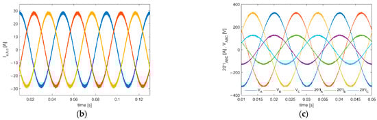
Figure 17.
Novel variation of IMC-based topology proposed in [124]. (a) respective topology. (b) output currents. (c) grid voltages and currents.
6. Grid Integration and Interface of Mobility Technologies
Electrical vehicles (EV) are expected to become the standard in the coming years. They may become an important asset to reduce fossil fuel dependency and provide a cleaner and less noisy environment in urban areas and city centres. One of the challenges concerning the growth of EVs depends on the availability of charging stations for long-range trips. Without an infrastructure that can recharge the vehicle in any region at any time most consumers will not consider buying an EV. In addition to this, the increasing number of EVs will also represent a substantial increase in the consumed electrical energy. The global electricity consumption from EVs is projected to reach 550 terawatt-hours by the year 2030 [125]. To meet this demand the number of EV charging stations and their installed power will require a massive increase.
Nowadays, AC charging stations from public facilities allow a maximum charging rate within the range of 22 kW to 43 kW [126], making use of the AC/DC EV onboard charger to convert AC power supplied by the grid into DC power that feeds and recharges the EV batteries.
DC charging stations are a good option to reduce the charging time and increase the charging power, as they convert AC to DC power and supply directly the car’s battery bypassing the EV´s onboard charger. These stations are designed to supply power ranging from 50 kW up to 200 kW [126]. However, they are more expensive and technologically more complex than AC charging stations and that is why recent research has been focused on DC charging topologies and control methods for vehicle-to-grid (V2G) and grid-to-vehicle (G2V) applications.
6.1. Matrix Converters in Direct Current (DC) Fast-Charging Stations
Charging stations are expected to have near unity power factor, high power density and low THD. CSR are one of the suitable topologies to tackle these challenges. They are characterized by its high-power density while providing the ability to improve the quality of the grid currents and guarantee unity power factor in the connection to the grid [127]. The scheme of a CSR can be obtained with a 3 × 2 DMC as shown in Figure 18.
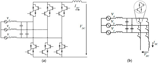
Figure 18.
AC/DC matrix topology. (a) Converter representation (b) simplified representation.
Many DC fast charging topologies often use a bulky capacitor on the DC link, while matrix converters can link the AC source to the battery with minimum filtering components and without the requirement of an additional DC–DC converter [128], still allowing bidirectional power flow. The absence of an energy storage link makes this topology an attractive alternative to the VSI as the size of the converter can be reduced and a higher reliability of the system can be achieved [129,130].
For safety reasons, DC fast-charging stations may require galvanic isolation between the AC grid and the DC link [131]. In [132] the author proposed a resonant matrix converter topology for a 500 V DC fast-charging station that uses a high-frequency transformer to guarantee galvanic isolation with increased power density.
Several modulation strategies have been proposed to control the CSR [133,134]. In [135] an ultrasparse matrix rectifier topology is applied to a battery charger where only 3 switching components are used. It provides low harmonic distortion in absorbed currents and a near unity power factor is achieved over a wide operating output power range. However, this topology does not allow bidirectional power flow.
6.2. Matrix Converters in Energy Storage Applications
In V2G applications the converter needs to operate in 2 modes: charging mode and discharging mode hence bidirectional CSI are essential to these applications. CSI can use the energy stored in the batteries by injecting power back into the grid, to help balancing the generation and consumption of energy [136]. In the scope of demand response in SGs, the owner of the EV can economically benefit from having the vehicle connected to the grid by providing voltage regulation and reactive power compensation to the grid. In [137], the authors proposed a single-stage topology for an energy storage system featuring galvanic isolation between the grid and the energy storage device. One CSI is used in [138] for a V2G application, where a sectionalized optimized modulation strategy is proposed that reduces the output current ripple.
As an example, simulation results using a CSR supplying power to a set of batteries are shown in Figure 19. Two similar batteries are connected to a 450 V DC bus at different instants and the input of the CSR is connected to a 400 V/690 V three-phase system. A non-linear controller was designed and implemented for this situation and is able to (1) control the output voltage to track the value 450 V; (2) control the output current ripple to be bounded by a specified limit and (3) adjust the input power factor to be near unity.
Figure 19.
(a) Output voltage (b) output current of the current source rectifier (CSR).
Figure 20 shows the grid voltages and currents in each phase where it is possible to verify that the current waveform is in phase with the input voltage waveform and the power factor is very close to unity.
Figure 20.
Simulation results of the proposed converter: input voltages (blue) and input currents (orange).
7. Sustainable Transportation Applications Enabled by the Use of Matrix Converters
The path towards more sustainable transportation plays a key role in the urgent need to reduce CO2 emissions. Accounting for almost one seventh of the global CO2 emissions and with a rising trend, the transportation sector requires the development of new technologies able to reduce the carbon footprint. This section presents contributions of matrix converters that aim to reach such sustainability in the aviation, marine and railway transports.
7.1. More Electric Aircraft
With the increasing growth of air traffic passenger demands, the aviation sector faces a wide set of new challenges. Civil aircraft represent 2.5% of the total carbon dioxide emissions [139], a figure that will likely grow in the future years, not only due to the increasing demand of this sector, but also due to the transition of road transportation technologies to reduced carbon footprint transports such as EVs.
More Electric Aircraft is a proposed concept in which the typical hydraulic, pneumatic and mechanical power sources that are required for all secondary power loads other than the aircraft thrust itself are replaced by electric power sources, promising increased efficiency, versatility, fault tolerance and weight reduction.
Power electronics is the key enabling technology for electrification of aircraft [140], [141]. The need to build complex power systems with both AC and DC high-power buses at different voltages and different frequencies, while attaining extremely high power densities, is a current and a future challenge that yet requires more research and development.
The inherent power density characteristics of matrix converters makes them good candidates to enable prominent technologies in the More Electric Aircraft, especially for AC/AC conversion [142].
The use of a matrix converter as a ground power unit (GPU) has been proposed in [143] for the generation of high-quality 400 Hz three-phase supply featuring a 4 leg direct matrix converter.
Matrix converters have also been proposed to convert power from the variable frequency generator (360 Hz–800 Hz) to a constant 400 Hz 110 VAC 3 Phase power bus [144] highlighting the minimum filtering requirements of the proposed solution. The use of indirect matrix converters as an interface between the generator and the 400 Hz bus is proposed in [145] where decoupled control strategies are provided for starting and generator operations. Matrix converters also allow the use of multi-phase generators such as shown in [146,147], reducing the generators stress and increasing the overall reliability. New matrix converter-based topologies such as that proposed in [148] allow the creation of both a three-phase 400 Hz and DC buses using an indirect matrix converter with an additional intermediate stage for the regulation of a DC bus.
Even though some authors do not consider the matrix converter as the preferred alternative for AC/DC conversion for More Electric Aircraft [142] several authors draw attention to the benefits of the use of matrix converters combined with high frequency transformers to create isolated DC buses [149]. Non isolated AC/DC matrix converters for aircraft use can also be found in literature [150], where authors suggest that the input power quality and the power density of the proposed converter makes it a desirable solution for large step-down voltage gains.
Electro Mechanical Actuators (EMAs) are also a major component of the More Electric Aircraft where the use of matrix converters can be beneficial especially when the EMA supply is provided in AC. One particular application of a matrix converter as a brushless DC motor driver is presented in [151], where a fault tolerant controller is developed for a five-output phase matrix converter-based driver. A comparison between a single stage matrix converter and dual-stage CSI-VSI drivers for EMAs is presented in [151] revealing efficiency advantages of the use of a single stage direct matrix converter that ultimately leads to less heatsink requirements and, therefore, higher power density.
7.2. Marine and Railway Aplications
Matrix converters can be used in electrical propulsion systems between generators and propulsion motors that power ships, they allow variable motor speed, provide efficient operation across the output power range and maximize volumetric density and weight which are extremely important in marine applications [152].
An application of single phase matrix converters can be found in [153] where a configuration for a main traction converter for locomotives with a medium frequency transformer operating at 400 Hz, and a cascade association of single phase matrix converters is proposed in order to withstand a supply voltage of 25 kV, resulting in a reduction of losses, weight and volume. The control strategies for this topology can be found in [154].
8. Challenges and Research Needs of Matrix Converters
As briefly approached on this work, developments on semiconductor technologies will have significant impact on the successful industrial penetration of matrix converter-based solutions for the promising future applications described throughout this work, to tackle the MC main challenges of higher efficiency and higher voltage operation capability. As a converter mainly composed by semiconductor switches, it is expected that matrix converters will benefit the most from breakthroughs in semiconductor technologies.
One such breakthrough is the wideband-gap device which is now widely available on the power semiconductor market. Silicon carbide (SiC) MOSFETs/IGBTs and gallium nitride (GaN) JFETs are two semiconductor technologies that enable the use of matrix converters with higher efficiencies, higher withstand voltages while improving power density.
Bidirectional JFETs [155], as depicted in Figure 21, could be the ultimate semiconductor switch for matrix converters since they provide a four-quadrant controlled switch using only one channel and a dual gate drive. This effectively addresses the problem of having two semiconductor devices (transistors or diodes) in series with the current path, resulting in reduced conduction losses. A matrix converter with 98% efficiency using GaN Bi-directional switches has been demonstrated in [156] where the characteristics of this switch are compared to the typical IGBT + Diode-based switch.
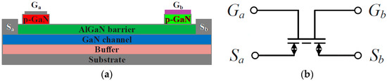
Figure 21.
Bi-directional gallium nitride (GaN) high-electron mobility transistor (HEMT) junction field effect transistors (JFET): (a) structure, (b) symbol voltages and currents (adapted from [155]).
While GaN JFETS are candidates to improve Matrix converter efficiency, new compound semiconductor materials such as Ga2O3 may strongly increase the high voltage capability of matrix converters. Gallium oxide bandgap is nearly 5 electron volts, therefore larger then GaN (3.4 eV) and well above silicon (1.1 eV). Thus, while the silicon critical field strength is typically hundreds of kV/cm, and about 3.3 MV/cm in GaN, in Ga2O3 it now attains 5.3 MV/cm and may reach 8 MV/cm (800 V/μm) [157]. Gallium oxide may achieve high operating voltages using just a few μm of Ga2O3 (7 kV would require 10 μm, while a comparable Si IGBT needs above 100 μm). Although semiconductor materials such as diamond and aluminium nitride present even larger bandgaps, unfortunately they do not allow ion-implantation of dopants during epitaxial growth like Ga2O3. This feature of Ga2O3 allows the use of well established commercial lithography and processing techniques in use for silicon devices. Moreover, it is possible to make large wafers (150 mm) of crystalline Ga2O3, and the oxide thermal stability allows its production using high-volume commercial techniques developed to make silicon wafers, such as edge-defined, or film-fed crystal growth [157]. Recently, Ga2O3 JFETs with operation like the high-electron mobility transistor (HEMT) were developed showing on-state resistances similar to GaN HEMTs.
The main weaknesses of Ga2O3 are the low thermal conductivity, one-tenth of SiC and one-fifth that of Silicon, and the lack of p-type doped semiconductors. While the lack of p-types is not a problem for power matrix converters, the low thermal conductivity may be resolved by using high thermal conductivity dielectric fillers to shunt heat from the contact electrodes and the top µm of the material (where most of the heat is generated) to a suitable heat sink.
Compared to a 1200 V, 3 kW Silicon matrix converter switching at 20 kHz, a Silicon Carbide matrix converter switching at 150 kHz, and operating at higher temperature can reduce the packaging volume to one-third of the silicon size, while it may be expected that a comparable Ga2O3 matrix converter could reach the MHz range with half the size of the SiC package. However, much research must be done to achieve fast multi-kilovolt-class power transistors. In particular, as Ga2O3 may attain frequencies in the 10 GHz range [157], research on new magnetic and dielectric materials must be undertaken before the Ga2O3 disruptive technology may be ready for commercial applications. Meanwhile, given the high voltage and high operating frequency, research on analysis and modelling of bidirectional JFETs, on mitigation of switching oscillations in JFET-based bidirectional switches, on integrated drivers with short circuit protection, on the commutation of bidirectional JFET in matrix converters, together with research on magnetic materials, electromagnetic shielding, and input and output filters should be carried on.
In terms of topologies, the challenges of matrix converters concentrate on improving the efficiency of transmission by increasing modularity, power density and reducing power losses. For instance, modular topologies with fewer stages of conversion and lower switch count per module could be capable of replacing the state-of-the-art converters in new applications like those described in this work. On hybrid applications that need galvanic isolation in the interconnection of AC and DC microgrids, the development of topologies that provide soft switching capability when supplying high-frequency transformers will lead to more compact and efficient systems.
Specifically, for the applications of SSTs, a novel topology in Figure 22 has the potential research and future application value where four bidirectional switches are replaced by three bidirectional switches at the primary side of the transformer and only one H-bridge with bidirectional switches is used at the secondary side, leading to a reduced switch count for the entire system compared to the structure in [29]. In the meantime, this topology also has the possibility of constructing a hybrid grid using less conversion stages compared to the conventional SST’s topologies in [158] where a DC link is unavoidable when constructing a hybrid grid system.
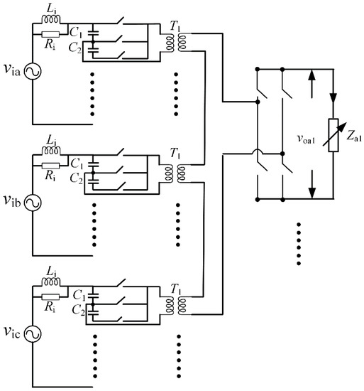
Figure 22.
A novel topology proposed for the applications of SSTs.
One of the challenges is the balancing of the capacitor voltages since capacitors in series are generally a preferred solution for the high voltage side of SSTs [159,160]. Along with controllers, modulation methods are extremely important to ensure adequate balancing of the capacitor voltages. Figure 23 depicts the influence of modulation methods in the capacitor voltages where a triangular carrier for a half-Venturini modulator wave yields balanced capacitor voltages (Figure 23a), whereas a sawtooth carrier yields unbalanced capacitor voltages (Figure 23b).
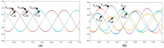
Figure 23.
Capacitor voltages with different modulation. (a) Capacitor voltages of half-Venturini adopted with triangle carrier wave (balanced); (b) capacitor voltages of half-Ventruini adopted with sawtooth carrier wave (unbalanced).
Such applications require novel control strategies to tackle these emerging topologies and functions. Currently, MPC algorithms in matrix converters allow a higher number of degrees of freedom by using an appropriate cost function capable of dealing with several goals at once, choosing the optimal available state that minimizes deviations from set-points. On the other hand, in specific applications such as electric drives, matrix converter topologies may contain enough semiconductors to lead to an unbearable number of possible switching states for the MPC. Research to use the redundant states for operation under faulty semiconductors is needed. New approaches need to be developed to account for the upcoming challenges on smart grids and sustainable transportation such as emulating inertia, multilayer control, improve power quality, managing energy storage systems, among others.
Non-linear controllers such as Lyapunov-based methods and backstepping are promising techniques that can make use of high-frequency modulation techniques taking advantage of the allowable high switching frequency of wideband-gap devices.
Meanwhile, the arrangement of FPGAs and microprocessors in the same unit, such as system-on-chip technology may facilitate the implementation of matrix converters by allowing the processes of control, modulation and bidirectional switches commutation to be implemented faster on the same chip.
9. Conclusions
This work focused on presenting matrix converter applications on future grid, transportation and drive innovation technologies, based on the current research trends supported by an extensive literature review. The contributions of matrix converters were divided into 5 categories, technologies for smart and resilient grids, renewables connection to the grid, innovation in electrical drives, integration of E mobility technologies and evolution towards more sustainable transportation.
It is intended to show that the matrix converter has the potential to be part of cutting-edge research to improve these future technologies where all of them play a major role in the sustainability of industry, cities, mobility, and energy production.
The use of matrix converters in these applications is more relevant now than ever before mainly by virtue of breakthroughs in semiconductors technologies. Matrix converters rely almost uniquely on semiconductor devices, allowing considerably higher power densities and increased robustness by decreasing the usage of passive components and enabling more fault-tolerant converter topologies. These advantages are highlighted across the whole spectrum of works reviewed in this paper certifying the matrix converter as a viable candidate to enable a set of technologies that are decisive to the evolution of the topics covered in this work.
The paper proposes and discusses some research areas with space for improvement, mainly concerning advanced power devices, new topologies, modern control strategies and modulation techniques. Progresses in the semiconductor industry and in digital processors technology may prove worthy to overcome efficiency and high-voltage capability challenges. This will make matrix converters a viable solution for future large-scale applications.
Author Contributions
Conceptualization, A.B., G.P., P.C., S.F.P. and J.F.S.; methodology, A.B., G.P., P.C., L.Z., T.G., S.F.P. and J.F.S.; investigation, A.B., G.P., P.C., L.Z., T.G.; writing—original draft preparation, A.B., G.P., P.C., L.Z., T.G.; writing—review and editing, S.F.P. and J.F.S.; supervision, S.F.P. and J.F.S. All authors have read and agreed to the published version of the manuscript.
Funding
This work was supported in part by Portugal funds through Fundação para a Ciência e Tecnologia (FCT) with project reference UIDB/50021/2020, by project PTDC/EEI-EE/32550/2017 and by FCT PhD grants with references SFRH/BD/146591/2019, SFRH/BD/146619/2019 and SFRH/BD/129864/2017.
Data Availability Statement
Base implementation in VHDL of a current-based four step commutation method is available in the following link: https://github.com/pccosta/MatrixConverter4StepCommutation (accessed on 18 May 2021).
Conflicts of Interest
The authors declare no conflict of interest.
References
- Wheeler, P.W.; Rodríguez, J.; Clare, J.C.; Empringham, L.; Weinstein, A. Matrix converters: A technology review. IEEE Trans. Ind. Electron. 2002, 49, 276–288. [Google Scholar] [CrossRef]
- Zhou, K.; Huang, L.; Luo, X.; Li, Z.; Li, J.; Dai, G.; Zhang, B. Characterization and Performance Evaluation of the Superjunction RB-IGBT in Matrix Converter. IEEE Trans. Power Electron. 2018, 33, 3289–3301. [Google Scholar] [CrossRef]
- Takahashi, H.; Kaneda, M.; Minato, T. 1200V class reverse blocking IGBT (RB-IGBT) for AC matrix converter. In Proceedings of the IEEE International Symposium on Power Semiconductor Devices and ICs (ISPSD), Kitakyushu, Japan, 24–27 May 2004; Volume 16, pp. 121–124. [Google Scholar]
- Friedli, T.; Kolar, J.W. Milestones in matrix converter research. IEEJ J. Ind. Appl. 2012, 1, 2–14. [Google Scholar] [CrossRef]
- Nguyen-Duy, K.; Liu, T.H.; Chen, D.F.; Hung, J.Y. Improvement of matrix converter drive reliability by online fault detection and a fault-tolerant switching strategy. IEEE Trans. Ind. Electron. 2012, 59, 244–256. [Google Scholar] [CrossRef]
- Dasika, J.D.; Saeedifard, M. A fault-tolerant strategy to control the matrix converter under an open-switch failure. IEEE Trans. Ind. Electron. 2015, 62, 680–691. [Google Scholar] [CrossRef]
- Khwan-On, S.; de Lillo, L.; Empringham, L.; Wheeler, P. Fault-tolerant matrix converter motor drives with fault detection of open switch faults. IEEE Trans. Ind. Electron. 2011, 59, 257–268. [Google Scholar] [CrossRef]
- Obi, M.; Bass, R. Trends and challenges of grid-connected photovoltaic systems—A review. Renew. Sustain. Energy Rev. 2016, 58, 1082–1094. [Google Scholar] [CrossRef]
- Mohd, A.; Ortjohann, E.; Schmelter, A.; Hamsic, N.; Morton, D. Challenges in integrating distributed Energy storage systems into future smart grid. In Proceedings of the 2008 IEEE International Symposium on Industrial Electronics, Cambridge, UK, 30 June–2 July 2008; pp. 1627–1632. [Google Scholar]
- Milano, F.; Dorfler, F.; Hug, G.; Hill, D.J.; Verbič, G. Foundations and challenges of low-inertia systems (Invited Paper). In Proceedings of the 20th Power Systems Computation Conference, PSCC 2018, Dublin, Ireland, 11–15 June 2018; pp. 1–25. [Google Scholar]
- Selvan, K.C.; Arunsaiikar, G. Grid integration of hybrid renewable energy system using versatile matrix converter. In Proceedings of the 2nd IEEE National Conference on Emerging Trends in New and Renewable Energy Sources and Energy Management (NCET NRES EM 2014), Chennai, India, 16–17 December 2014; IEEE: New York, NY, USA, 2015. No. Vmc. pp. 153–158. [Google Scholar]
- Sun, Y.; Li, X.; Su, M.; Wang, H.; Dan, H.; Xiong, W. Indirect matrix converter-based topology and modulation schemes for enhancing input reactive power capability. IEEE Trans. Power Electron. 2015, 30, 4669–4681. [Google Scholar] [CrossRef]
- Gambôa, P.; Silva, J.F.; Pinto, S.F.; Margato, E. Predictive optimal matrix converter control for a dynamic voltage restorer with flywheel energy storage. In Proceedings of the IECON (Industrial Electronics Conference), Porto, Portugal, 3–5 November 2009; No. 1. pp. 759–764. [Google Scholar]
- Liserre, M.; Buticchi, G.; Andresen, M.; de Carne, G.; Costa, L.F.; Zou, Z.X. The Smart Transformer: Impact on the Electric Grid and Technology Challenges. IEEE Ind. Electron. Mag. 2016, 10, 46–58. [Google Scholar] [CrossRef]
- Huber, J.E.; Kolar, J.W. Solid-State Transformers: On the Origins and Evolution of Key Concepts. IEEE Ind. Electron. Mag. 2016, 10, 19–28. [Google Scholar] [CrossRef]
- Lopez, J.V.; Garcia, S.M.; Rodriguez, J.C.C.; Garcia, R.V.; Fernandez, S.M.; Olay, C.C. Electronic tap-changing stabilizers for medium-voltage lines optimum balanced circuit. IEEE Trans. Power Deliv. 2012, 27, 1909–1918. [Google Scholar] [CrossRef]
- Lozano, J.M.; Ramirez, J.M.; Correa, R.E. A novel Dynamic Voltage Restorer based on matrix converters. In Proceedings of the International Symposium: Modern Electric Power Systems, MEPS’10, Wrocław, Poland, 20–22 September 2010. No. 1145. [Google Scholar]
- Shabanpour, A.; Seifi, A.R. A Dynamic Voltage Restorer Based on matrix converter with fuzzy controller. Adv. Electr. Electron. Eng. 2012, 10, 143–151. [Google Scholar] [CrossRef]
- Szczesniak, P.; Kaniewski, J. Hybrid Transformer with Matrix Converter. IEEE Trans. Power Deliv. 2016, 31, 1388–1396. [Google Scholar] [CrossRef]
- Szczesniak, P.; Kaniewski, J. A voltage regulator/conditioner based on a hybrid transformer with matrix converter. In Proceedings of the IECON (Industrial Electronics Conference), Dallas, TX, USA, 29 October–1 November 2014; pp. 3292–3297. [Google Scholar]
- Pinto, S.F.; Alcaria, P.; Monteiro, J.; Silva, J.F. Matrix Converter-Based Active Distribution Transformer. IEEE Trans. Power Deliv. 2016, 31, 1493–1501. [Google Scholar] [CrossRef]
- Szcześniak, P. Comparison of control methods for a dynamic voltage restorer using a three-phase matrix converter. Simulation 2016, 92, 1053–1063. [Google Scholar] [CrossRef]
- Kolar, J.W.; Ortiz, G. Solid-State-Transformers: Key Components of Future Traction and Smart Grid Systems. In Proceedings of the 2014 International Power Electronics Conference, Hiroshima, Japan, 18–21 May 2014; No. Ipec. pp. 22–35. [Google Scholar]
- Boroyevich, D.; Cvetković, I.; Dong, D.; Burgos, R.; Wang, F.; Lee, F. Future electronic power distribution systems—A contemplative view. In Proceedings of the International Conference on Optimisation of Electrical and Electronic Equipment, OPTIM, Brasov, Romania, 20–22 May 2010; pp. 1369–1380. [Google Scholar]
- Dujic, D.; Kieferndorf, F.; Canales, F.; Drofenik, U. Power electronic traction transformer technology. In Proceedings of the 2012 IEEE 7th International Power Electronics and Motion Control Conference—ECCE Asia, IPEMC 2012, Harbin, China, 2–5 June 2012; IEEE: New York, NY, USA, 2012; Volume 1, pp. 636–642. [Google Scholar]
- Satyamsetti, V.; Michealides, A.; Hadjiantonis, A. Forecasting on solid state transformer applications. In Proceedings of the International Conference on Intelligent Sustainable Systems, ICISS 2017, Palladam, India, 7–8 December 2017; No. Iciss. pp. 330–335. [Google Scholar]
- Pinto, S.; Mendes, P.; Silva, J.F. Modular Matrix Converter Based Solid State Transformer for smart grids. Electr. Power Syst. Res. 2016, 136, 189–200. [Google Scholar] [CrossRef]
- Nasir, U.; Costabeber, A.; Wheeler, P.; Rivera, M.; Clare, J. A Three-Phase Modular Isolated Matrix Converter. IEEE Trans. Power Electron. 2019, 34, 11760–11773. [Google Scholar] [CrossRef]
- Nasir, U.; Costabeber, A.; Rivera, M.; Wheeler, P.; Clare, J. A Leakage-Inductance-Tolerant Commutation Strategy for Isolated AC/AC Converters. IEEE J. Emerg. Sel. Top. Power Electron. 2019, 7, 467–479. [Google Scholar] [CrossRef]
- Liu, Y.; Liu, Y.; Ge, B.; Abu-Rub, H. Interactive Grid Interfacing System by Matrix-Converter-Based Solid State Transformer with Model Predictive Control. IEEE Trans. Ind. Inform. 2020, 16, 2533–2541. [Google Scholar] [CrossRef]
- Banaei, M.R.; Salary, E. Mitigation of voltage sag, swell and power factor correction using solid-state transformer based matrix converter in output stage. Alex. Eng. J. 2014, 53, 563–572. [Google Scholar] [CrossRef]
- Saha, J.; Yadav, G.N.B.; Panda, S.K. A Matrix-Based Solid-State-Transformer for A Hybrid Nanogrid. In Proceedings of the 2018 IEEE International Conference on Power Electronics, Drives and Energy Systems, Chennai, India, 18–21 December 2018. [Google Scholar]
- Divan, D.; Johal, H. Distributed FACTS—A new concept for realizing grid power flow control. IEEE Trans. Power Electron. 2007, 22, 2253–2260. [Google Scholar] [CrossRef]
- Rohouma, W.; Balog, R.S.; Peerzada, A.A.; Begovic, M.M. Development of a capacitor-less D-STATCOM for power quality improvement in low voltage network. In Proceedings of the 2019 IEEE 13th International Conference on Compatibility, Power Electronics and Power Engineering, CPE-POWERENG 2019, Sonderborg, Denmark, 23–25 April 2019; pp. 1–5. [Google Scholar]
- Shadmand, M.B.; Mosa, M.; Balog, R.S.; Abu-Rub, H. Model predictive control of a capacitorless matrix converter-based STATCOM. IEEE J. Emerg. Sel. Top. Power Electron. 2017, 5, 796–808. [Google Scholar] [CrossRef]
- Holtsmark, N.; Molinas, M. Reactive power compensation capability of a matrix converter-based FACTS device. In Proceedings of the 2011 IEEE PES Trondheim PowerTech: The Power of Technology for a Sustainable Society, POWERTECH 2011, Trondheim, Norway, 19–23 June 2011; pp. 1–6. [Google Scholar]
- Monteiro, J.; Silva, J.F.; Pinto, S.F.; Palma, J. Matrix converter-based unified power-flow controllers: Advanced direct power control method. IEEE Trans. Power Deliv. 2011, 26, 420–430. [Google Scholar] [CrossRef]
- Monteiro, J.; Silva, J.F.; Pinto, S.F.; Palma, J. Linear and sliding-mode control design for matrix converter-based unified power flow controllers. IEEE Trans. Power Electron. 2014, 29, 3357–3367. [Google Scholar] [CrossRef]
- Kroposki, B.; Johnson, B.; Zhang, Y.; Gevorgian, V.; Denholm, P.; Hodge, B.-M.; Hannegan, B. Achieving a 100% Renewable Grid: Operating Electric Power Systems with Extremely High Levels of Variable Renewable Energy. IEEE Power Energy Mag. 2017, 15, 61–73. [Google Scholar] [CrossRef]
- Asrari, A.; Wu, T.; Lotfifard, S. The Impacts of Distributed Energy Sources on Distribution Network Reconfiguration. IEEE Trans. Energy Convers. 2016, 31, 606–613. [Google Scholar] [CrossRef]
- Teodorescu, R.; Liserre, M.; Rodríguez, P. Grid Converters for Photovoltaic and Wind Power Systems; John Wiley & Sons Ltd.: Hoboken, NJ, USA, 2011. [Google Scholar]
- Singh, B.; Chandra, A.; Al-Haddad, K. Power Quality Problems and Mitigation Techniques; John Wiley & Sons Ltd.: Hoboken, NJ, USA, 2015. [Google Scholar]
- Tang, C.-Y.; Chen, Y.-T.; Chen, Y.-M. PV Power System with Multi-Mode Operation and Low-Voltage Ride-Through Capability. IEEE Trans. Ind. Electron. 2015, 62, 7524–7533. [Google Scholar] [CrossRef]
- Baran, M.E.; Hooshyar, H.; Shen, Z.; Huang, A. Accommodating High PV Penetration on Distribution Feeders. IEEE Trans. Smart Grid 2012, 3, 1039–1046. [Google Scholar] [CrossRef]
- Marei, M.I.; El-Saadany, E.F.; Salama, M.M.A. A Flexible DG Interface Based on a New RLS Algorithm for Power Quality Improvement. IEEE Syst. J. 2012, 6, 68–75. [Google Scholar] [CrossRef]
- Ghanbari, T.; Farjah, E.; Naseri, F. Power quality improvement of radial feeders using an efficient method. Electr. Power Syst. Res. 2018, 163, 140–153. [Google Scholar] [CrossRef]
- Gayatri, M.T.L.; Parimi, A.M.; Kumar, A.V.P. A review of reactive power compensation techniques in microgrids. Renew. Sustain. Energy Rev. 2018, 81, 1030–1036. [Google Scholar] [CrossRef]
- Ali, M.S.; Haque, M.M.; Wolfs, P. A review of topological ordering based voltage rise mitigation methods for LV distribution networks with high levels of photovoltaic penetration. Renew. Sustain. Energy Rev. 2019, 103, 463–476. [Google Scholar] [CrossRef]
- López-Erauskin, R.; Geury, T.; González, A.; Gyselinck, J.; Hervás, M.E.; Fabre, A. Testing the Enhanced Functionalities of Commercial PV Inverters Under Realistic Atmospheric and Abnormal Grid Conditions. In Proceedings of the 5th Solar Integration Workshop, Brussels, Belgium, 19–20 October 2015. [Google Scholar]
- Bae, Y.; Vu, T.-K.K.; Kim, R.-Y.Y. Implemental control strategy for grid stabilization of grid-connected PV system based on German grid code in symmetrical low-to-medium voltage network. IEEE Trans. Energy Convers. 2013, 28, 619–631. [Google Scholar] [CrossRef]
- Saadat, N.; Choi, S.S.; Vilathgamuwa, D.M. A Series-Connected Photovoltaic Distributed Generator Capable of Enhancing Power Quality. IEEE Trans. Energy Convers. 2013, 28, 1026–1035. [Google Scholar] [CrossRef]
- Zeng, Z.; Yang, H.; Tang, S.; Zhao, R. Objective-Oriented Power Quality Compensation of Multifunctional Grid-Tied Inverters and Its Application in Microgrids. IEEE Trans. Power Electron. 2015, 30, 1255–1265. [Google Scholar] [CrossRef]
- Wandhare, R.G.; Agarwal, V. Reactive Power Capacity Enhancement of a PV-Grid System to Increase PV Penetration Level in Smart Grid Scenario. IEEE Trans. Smart Grid 2014, 5, 1845–1854. [Google Scholar] [CrossRef]
- Geury, T.; Pinto, S.; Gyselinck, J. Current source inverter-based photovoltaic system with enhanced active filtering functionalities. IET Power Electron. 2015, 8, 2483–2491. [Google Scholar] [CrossRef]
- Chilipi, R.R.; al Sayari, N.; Beig, A.R.; Al Hosani, K. A Multitasking Control Algorithm for Grid-Connected Inverters in Distributed Generation Applications Using Adaptive Noise Cancellation Filters. IEEE Trans. Energy Convers. 2016, 31, 714–727. [Google Scholar] [CrossRef]
- Madonna, V.; Migliazza, G.; Giangrande, P.; Lorenzani, E.; Buticchi, G.; Galea, M. The Rebirth of the Current Source Inverter: Advantages for Aerospace Motor Design. IEEE Ind. Electron. Mag. 2019, 13, 65–76. [Google Scholar] [CrossRef]
- Lorenzani, E.; Immovilli, F.; Migliazza, G.; Frigieri, M.; Bianchini, C.; Davoli, M. CSI7: A modified three-phase current-source inverter for modular photovoltaic applications. IEEE Trans. Ind. Electron. 2017, 64, 7. [Google Scholar] [CrossRef]
- Youssef, E.; Costa, P.; Pinto, S.; Amin, A.; Samahy, A. Direct Power Control of a Single Stage Current Source Inverter Grid-Tied PV System. Energies 2020, 13, 3165. [Google Scholar] [CrossRef]
- Dash, P.P.; Kazerani, M. Dynamic modeling and performance analysis of a grid-connected current-source inverter-based photovoltaic system IEEE Trans. IEEE Trans. Sustain. Energy 2011, 2, 4. [Google Scholar] [CrossRef]
- Sahan, B.; Araújo, S.V.; Nöding, C.; Zacharias, P. Comparative Evaluation of Three-Phase Current Source Inverters for Grid Interfacing of Distributed and Renewable Energy Systems. IEEE Trans. Power Electron. 2011, 26, 2304–2318. [Google Scholar] [CrossRef]
- Cossutta, P.; Aguirre, M.P.; Cao, A.; Raffo, S.; Valla, M.I. Single-Stage Fuel Cell to Grid Interface with Multilevel Current-Source Inverters. IEEE Trans. Ind. Electron. 2015, 62, 5256–5264. [Google Scholar] [CrossRef]
- Klumpner, C. A new single-stage current source inverter for photovoltaic and fuel cell applications using reverse blocking IGBTs. In Proceedings of the IEEE Power Electronics Specialists Conference, Orlando, FL, USA, 17–21 June 2007; pp. 1683–1689. [Google Scholar]
- Zhou, Y.; Huang, W.; Zhao, P.; Zhao, J. Coupled-inductor single-stage boost inverter for grid-connected photovoltaic system. IET Power Electron. 2014, 7, 259–270. [Google Scholar] [CrossRef]
- Guo, X.; Xu, D.; Wu, B. Four-Leg Current-Source Inverter with a New Space Vector Modulation for Common-Mode Voltage Suppression. IEEE Trans. Ind. Electron. 2015, 62, 6003–6007. [Google Scholar] [CrossRef]
- Anand, S.; Gundlapalli, S.K.; Fernandes, B.G. Transformer-Less Grid Feeding Current Source Inverter for Solar Photovoltaic System. IEEE Trans. Ind. Electron. 2014, 61, 5334–5344. [Google Scholar] [CrossRef]
- Photong, C.; Klumpner, C.; Wheeler, P. A current source inverter with series connected AC capacitors for photovoltaic application with grid fault ride through capability. In Proceedings of the 2009 35th Annual Conference of IEEE Industrial Electronics, Porto, Portugal, 3–5 November 2009. [Google Scholar]
- Geury, T.; Pinto, S.; Gyselinck, J.; Wheeler, P. An indirect matrix converter-based unified power quality conditioner for a PV inverter with enhanced power quality functionality. In Proceedings of the 2015 IEEE Innovative Smart Grid Technologies—Asia (ISGT ASIA), Bangkok, Thailand, 3–6 November 2015. [Google Scholar]
- Campanhol, L.B.G.; da Silva, S.A.O.; de Oliveira, A.A.; Bacon, V.D. Single-Stage Three-Phase Grid-Tied PV System with Universal Filtering Capability Applied to DG Systems and AC Microgrids. IEEE Trans. Power Electron. 2017, 32, 9131–9142. [Google Scholar] [CrossRef]
- Devassy, S.; Singh, B. Design and Performance Analysis of Three-Phase Solar PV Integrated UPQC. IEEE Trans. Ind. Appl. 2018, 54, 73–81. [Google Scholar] [CrossRef]
- Khadkikar, V. Enhancing Electric Power Quality Using UPQC: A Comprehensive Overview. IEEE Trans. Power Electron. 2012, 27, 2284–2297. [Google Scholar] [CrossRef]
- Geury, T.; Pinto, S.; Gyselinck, J. Direct control method for a PV system integrated in an Indirect Matrix Converter-based UPQC. In Proceedings of the 2016 the 4th IEEE International Conference on Smart Energy Grid Engineering, Oshawa, ON, Canada, 21–24 August 2016. [Google Scholar]
- Empringham, L.; Kolar, J.W.; Rodriguez, J.; Wheeler, P.W.; Clare, J.C. Technological issues and industrial application of matrix converters: A review. IEEE Trans. Ind. Electron. 2013, 60, 4260–4271. [Google Scholar] [CrossRef]
- Vijayagopal, M.; Silva, C.; Empringham, L.; de Lillo, L. Direct Predictive Current-Error Vector Control for a Direct Matrix Converter. IEEE Trans. Power Electron. 2019, 34, 1925–1935. [Google Scholar] [CrossRef]
- Hamouda, M.; Blanchette, H.F.; Al-Haddad, K. Unity Power Factor Operation of Indirect Matrix Converter Tied to Unbalanced Grid. IEEE Trans. Power Electron. 2016, 31, 1095–1107. [Google Scholar] [CrossRef]
- Pena, R.; Cardenas, R.; Reyes, E.; Clare, J.; Wheeler, P. Control of a Doubly Fed Induction Generator via an Indirect Matrix Converter with Changing DC Voltage. IEEE Trans. Ind. Electron. 2011, 58, 4664–4674. [Google Scholar] [CrossRef]
- Friedli, T.; Kolar, J.W.; Rodriguez, J.; Wheeler, P.W. Comparative Evaluation of Three-Phase AC/AC Matrix Converter and Voltage DC-Link Back-to-Back Converter Systems. IEEE Trans. Ind. Electron. 2012, 59, 4487–4510. [Google Scholar] [CrossRef]
- Kolar, J.W.; Schafmeister, F.; Round, S.D.; Ertl, H. Novel Three-Phase AC/AC Sparse Matrix Converters. IEEE Trans. Power Electron. 2007, 22, 1649–1661. [Google Scholar] [CrossRef]
- European Wind Energy Association. UpWind: Design Limits and Solutions for Very Large Wind Turbines; Brussels, Belgium. 2011; Available online: http://www.ewea.org/fileadmin/files/library/publications/reports/UpWind_Report.pdf (accessed on 1 May 2021).
- Mensou, S.; Essadki, A.; Nasser, T.; Idrissi, B.B. A direct power control of a DFIG based-WECS during symmetrical voltage dips. Prot. Control. Mod. Power Syst. 2020, 5, 1–12. [Google Scholar] [CrossRef]
- Cárdenas, R.; Peña, R.; Clare, J.; Wheeler, P. Analytical and experimental evaluation of a WECS based on a cage induction generator fed by a matrix converter. IEEE Trans. Energy Convers. 2011, 26, 204–215. [Google Scholar] [CrossRef]
- Mondal, S.; Kastha, D. Improved Direct Torque and Reactive Power Control of a Matrix-Converter-Fed Grid-Connected Doubly Fed Induction Generator. IEEE Trans. Ind. Electron. 2015, 62, 7590–7598. [Google Scholar] [CrossRef]
- Mondal, S.; Kastha, D. Maximum Active and Reactive Power Capability of a Matrix Converter-Fed DFIG-Based Wind Energy Conversion System. IEEE J. Emerg. Sel. Top. Power Electron. 2017, 5, 1322–1333. [Google Scholar] [CrossRef]
- Elizondo, J.L.; Olloqui, A.; Rivera, M.; Macias, M.E.; Probst, O.; Micheloud, O.M.; Rodriguez, J. Model-based predictive rotor current control for grid synchronization of a DFIG driven by an indirect matrix converter. IEEE J. Emerg. Sel. Top. Power Electron. 2014, 2, 715–726. [Google Scholar] [CrossRef]
- Jiang, Z.; Xie, K. Identification and effect analysis of the weak parts of large-scale wind energy conversion system using the reliability tracing technique. Prz. Elektrotechniczny 2012, 88, 192–196. [Google Scholar]
- Semken, R.S.; Polikarpova, M.; Röyttä, P.; Alexandrova, J.; Pyrhönen, J.; Nerg, J.; Mikkola, A.; Backman, J. Direct-drive permanent magnet generators for high-power wind turbines: Benefits and limiting factors. IET Renew. Power Gener. 2012, 6, 1–8. [Google Scholar] [CrossRef]
- Hojabri, H.; Mokhtari, H.; Chang, L. Reactive Power Control of Permanent-Magnet. IEEE Trans. Power Deliv. 2013, 28, 575–584. [Google Scholar] [CrossRef]
- Karaman, E.; Farasat, M.; Trzynadlowski, A.M. Indirect matrix converters as generator-grid interfaces for wind energy systems. IEEE J. Emerg. Sel. Top. Power Electron. 2014, 2, 776–783. [Google Scholar] [CrossRef]
- Singh, A.; Benzaquen, J.; Mirafzal, B. Current Source Generator-Converter Topology for Direct-Drive Wind Turbines. IEEE Trans. Ind. Appl. 2018, 54, 1663–1670. [Google Scholar] [CrossRef]
- Diaz, M.; Cardenas, R.; Espinoza, M.; Rojas, F.; Mora, A.; Clare, J.C.; Wheeler, P. Control of Wind Energy Conversion Systems Based on the Modular Multilevel Matrix Converter. IEEE Trans. Ind. Electron. 2017, 64, 8799–8810. [Google Scholar] [CrossRef]
- Barrera-Cardenas, R.; Molinas, M. Comparative study of wind turbine power converters based on medium-frequency AC-link for offshore DC-grids. IEEE J. Emerg. Sel. Top. Power Electron. 2015, 3, 525–541. [Google Scholar] [CrossRef]
- Yuan, C.; Zhou, R.; Tong, M. Topologies and control of low-frequency alternating current for offshore wind farms based on modular multilevel matrix converter. J. Eng. 2019, 2019, 2271–2277. [Google Scholar] [CrossRef]
- Abebe, R.; Vakil, G.; Calzo, G.L.; Cox, T.; Lambert, S.; Johnson, M.; Gerada, C.; Mecrow, B. Integrated motor drives: State of the art and future trends. IET Electr. Power Appl. 2016, 10, 757–771. [Google Scholar] [CrossRef]
- Wang, J.; Li, Y.; Han, Y. Integrated Modular Motor Drive Design with GaN Power FETs. IEEE Trans. Ind. Appl. 2015, 51, 3198–3207. [Google Scholar] [CrossRef]
- Levi, E.; Bodo, N.; Dordevic, O.; Jones, M. Recent advances in power electronic converter control for multiphase drive systems. In Proceedings of the 2013 IEEE Workshop on Electrical Machines Design, Control and Diagnosis, Paris, France, 11–12 March 2013; pp. 158–167. [Google Scholar]
- Levi, E.; Bojoi, R.; Profumo, F.; Toliyat, H.A.; Williamson, S. Multiphase induction motor drives—A technology status review. IET Electr. Power Appl. 2007, 1, 489–516. [Google Scholar] [CrossRef]
- Levi, E. Multiphase electric machines for variable-speed applications. IEEE Trans. Ind. Electron. 2008, 55, 1893–1909. [Google Scholar] [CrossRef]
- Toulabi, M.S.; Salmon, J.; Knight, A.M. Design, Control, and Experimental Test of an Open-Winding IPM Synchronous Motor. IEEE Trans. Ind. Electron. 2017, 64, 2760–2769. [Google Scholar] [CrossRef]
- Araújo, A.V.R.R.S.; Rodrigues, R.A.; de Paula, H.; Baccarini, L.M.R. Premature Wear and Recurring Bearing Failures in an Inverter Driven Induction Motor—Part I: Investigation of the Problem. In Proceedings of the 2013 IEEE Industry Applications Society Annual Meeting, Lake Buena Vista, FL, USA, 6–11 October 2013; Volume 6, pp. 1–6. [Google Scholar]
- Gupta, R.K.; Mohapatra, K.K.; Somani, A.; Mohan, N. Direct-matrix-converter-based drive for a three-phase open-end-winding AC machine with advanced features. IEEE Trans. Ind. Electron. 2010, 57, 4032–4042. [Google Scholar] [CrossRef]
- Rząsa, J. Research on dual matrix converter feeding an open-end-winding load controlled with the use of rotating space vectors—Part I. In Proceedings of the IECON 2013—39th Annual Conference of the IEEE Industrial Electronics Society, Vienna, Austria, 10–13 November 2013; pp. 4919–4924. [Google Scholar]
- Rzasa, J.; Garus, G. Research on dual matrix converter feeding an open end winding load controlled with the use of rotating space vectors—Part II. In Proceedings of the IECON 2013—39th Annual Conference of the IEEE Industrial Electronics Society, Vienna, Austria, 10–13 November 2013; pp. 4925–4930. [Google Scholar]
- Iqbal, A.; Ahmed, S.M.; Abu-Rub, H. Space vector PWM technique for a three-to-five-phase matrix converter. IEEE Trans. Ind. Appl. 2012, 48, 697–707. [Google Scholar] [CrossRef]
- Ahmed, S.M.; Salam, Z.; Abu-Rub, H. An improved space vector modulation for a three-to-seven-phase matrix converter with reduced number of switching vectors. IEEE Trans. Ind. Electron. 2015, 62, 3327–3337. [Google Scholar] [CrossRef]
- Ahmed, S.M.; Iqbal, A.; Abu-Rub, H.; Rodriguez, J.; Rojas, C.A.; Saleh, M. Simple carrier-based PWM technique for a three-to-nine-phase direct ac-ac converter. IEEE Trans. Ind. Electron. 2011, 58, 5014–5023. [Google Scholar]
- Ali, M.; Iqbal, A.; Khan, M.R.; Ayyub, M.; Anees, M.A. Generalized Theory and Analysis of Scalar Modulation Techniques for a m × n Matrix Converter. IEEE Trans. Power Electron. 2017, 32, 4864–4877. [Google Scholar] [CrossRef]
- Ahmed, S.M.; Abu-Rub, H.; Salarti, Z.; Rivera, M.; Ellabban, O. Generalized carrier based pulse width modulation technique for a three to n-phase dual matrix converter. In Proceedings of the IECON 2014—40th Annual Conference of the IEEE Industrial Electronics Society, Dallas, TX, USA, 29 October–1 November 2014; pp. 3298–3304. [Google Scholar]
- Ahmed, S.M.; Abu-Rub, H.; Salam, Z. Space vector control of dual matrix converters based five-phase open-end winding drive. In Proceedings of the 2014 IEEE Conference on Energy Conversion, Johor Bahru, Malaysia, 13–14 October 2014; pp. 348–353. [Google Scholar]
- Ahmed, S.M.; Abu-Rub, H.; Salam, Z. Common-mode voltage elimination in a three-to-five-phase dual matrix converter feeding a five-phase open-end drive using space-vector modulation technique. IEEE Trans. Ind. Electron. 2015, 62, 6051–6063. [Google Scholar] [CrossRef]
- Rahman, K.; Iqbal, A.; Al-Hitmi, M.A.; Dordevic, O.; Ahmad, S. Performance Analysis of a Three-to-Five Phase Dual Matrix Converter Based on Space Vector Pulse Width Modulation. IEEE Access 2019, 7, 12307–12318. [Google Scholar] [CrossRef]
- Ahmed, S.M.; Salam, Z.; Abu-Rub, H. Common-mode voltage elimination in a three-to-seven phase dual matrix converter feeding a seven phase open-end induction motor drive. In Proceedings of the 2014 IEEE Conference on Energy Conversion, Johor Bahru, Malaysia, 13–14 October 2014; pp. 207–212. [Google Scholar]
- Nguyen, T.D.; Lee, H.H. Carrier-based PWM technique for three-to-five phase indirect matrix converters. In Proceedings of the IECON 2011—37th Annual Conference of the IEEE Industrial Electronics Society, Melbourne, Australia, 7–10 November 2011; pp. 3662–3667. [Google Scholar]
- Nguyen, T.D.; Lee, H.H. Development of a Three-to-Five-Phase Indirect Matrix Converter with Carrier-Based PWM Based on Space-Vector Modulation Analysis. IEEE Trans. Ind. Electron. 2016, 63, 13–24. [Google Scholar] [CrossRef]
- Rahman, K.; Iqbal, A.; Al-Emadi, N.; Ben-Brahim, L. Common mode voltage reduction in a three-to-five phase matrix converter fed induction motor drive. IET Power Electron. 2017, 10, 817–825. [Google Scholar] [CrossRef]
- Chai, M.; Xiao, D.; Dutta, R.; Fletcher, J.E. Space vector PWM techniques for three-to-five-phase indirect matrix converter in the overmodulation region. IEEE Trans. Ind. Electron. 2016, 63, 550–561. [Google Scholar] [CrossRef]
- Riedemann, J.; Cárdenas, R.; Clare, J.; Wheeler, P.; Blasco-gimenez, R. Control strategy of a dual-inverter system for an open-end winding induction machine based on indirect matrix converter. In Proceedings of the Power Electronics and Applications (EPE’14-ECCE Europe), Lappeenranta, Finland, 26–28 August 2014; pp. 1–8. [Google Scholar]
- Riedemann, J.; Pena, R.; Cárdenas, R.; Rivera, M.; Blasco-Gimenez, R.; Clare, J.; Wheeler, P. Control of an open-end winding induction machine via a two-output indirect matrix converter. In Proceedings of the IEEE Applied Power Electronics Conference and Exposition—APEC, Fort Worth, TX, USA, 16–20 March 2014; pp. 1537–1544. [Google Scholar]
- Riedemann, J.; Clare, J.C.; Wheeler, P.W.; Blasco-Gimenez, R.; Rivera, M.; Pena, R. Open-End Winding Induction Machine Fed by a Dual-Output Indirect Matrix Converter. IEEE Trans. Ind. Electron. 2016, 63, 4118–4128. [Google Scholar] [CrossRef]
- Tran, Q.H.; Nguyen, T.D.; Lee, H.H. A SVM method for five-leg indirect matrix converters with open-end winding load. In Proceedings of the 2015 9th International Conference on Power Electronics and ECCE Asia (ICPE-ECCE Asia), Seoul, Korea, 1–5 June 2015; pp. 934–939. [Google Scholar]
- Tran, Q.H.; Nguyen, T.D.; Lee, H.H. Three-vector modulation scheme to improve output performance for five-leg indirect matrix converter fed open-end load. In Proceedings of the 2016 IEEE 8th International Power Electronics and Motion Control. Conference (IPEMC-ECCE Asia), Hefei, China, 22–26 May 2016; pp. 2133–2138. [Google Scholar]
- Tran, Q.H.; Lee, H.H. A Three-Vector Modulation Strategy for Indirect Matrix Converter Fed Open-End Load to Reduce Common-Mode Voltage with Improved Output Performance. IEEE Trans. Power Electron. 2017, 32, 7904–7915. [Google Scholar] [CrossRef]
- Tewari, S.; Gupta, R.K.; Mohan, N. Three-level indirect matrix converter based open-end winding AC machine drive. In Proceedings of the IECON 2011—37th Annual Conference of the IEEE Industrial Electronics Society, Melbourne, Australia, 7–10 November 2011; No. 1. pp. 1636–1641. [Google Scholar]
- Tewari, S.; Gupta, R.K.; Somani, A.; Mohan, N. Indirect matrix converter based open-end winding AC drives with zero common-mode voltage. In Proceedings of the IEEE Applied Power Electronics Conference and Exposition—APEC, Long Beach, CA, USA, 20–24 March 2016; IEEE: New York, NY, USA, 2016; Volume 2016, pp. 1520–1527. [Google Scholar]
- Tewari, S.; Mohan, N. Matrix Converter Based Open-End Winding Drives with Common-Mode Elimination: Topologies, Analysis, and Comparison. IEEE Trans. Power Electron. 2017, 8993, 1–18. [Google Scholar] [CrossRef]
- Bento, A.; Luís, R.; Pinto, S.; Silva, J.F. A Novel Multilevel T-Type Indirect Matrix Converter for Three-phase Open-end AC Loads. In Proceedings of the IECON 2019—45th Annual Conference of the IEEE Industrial Electronics Society, Lisbon, Portugal, 14–17 September 2019; pp. 6575–6580. [Google Scholar]
- IEA. Global EV Outlook 2020; IEA: Paris, France, 2020. [Google Scholar]
- Chen, T.; Zhang, X.-P.; Wang, J.; Li, J.; Wu, C.; Hu, M.; Bian, H. A Review on Electric Vehicle Charging Infrastructure Development in the UK. J. Mod. Power Syst. Clean Energy 2020, 8, 193–205. [Google Scholar] [CrossRef]
- Chaudhry, H.; Bohn, T. A V2G application using DC fast charging and its impact on the grid. In Proceedings of the 2012 IEEE Transportation Electrification Conference and Expo (ITEC), Dearborn, MI, USA, 18–20 June 2012. [Google Scholar]
- Nguyen, T.-L.; Lee, H.-H. An Enhanced Control Strategy for AC-DC Matrix Converters under Unbalanced Grid Voltage. IEEE Trans. Ind. Electron. 2020, 67, 1718–1727. [Google Scholar] [CrossRef]
- Wang, H.; Blaabjerg, F. Reliability of Capacitors for DC-Link Applications in Power Electronic Converters-An Overview. IEEE Trans. Ind. Appl. 2014, 50, 3569–3578. [Google Scholar] [CrossRef]
- Song, Y.; Wang, B. Survey on Reliability of Power Electronic Systems. IEEE Trans. Power Electron. 2013, 28, 591–604. [Google Scholar] [CrossRef]
- Schrittwieser, L.; Leibl, M.; Kolar, J.W. 99% Efficient isolated three-phase matrix-type DAB buck-boost PFC rectifier. IEEE Trans. Power Electron. 2020, 35, 138–157. [Google Scholar] [CrossRef]
- Sandoval, J.J.; Essakiappan, S.; Enjeti, P. A bidirectional series resonant matrix converter topology for electric vehicle DC fast charging. In Proceedings of the IEEE Applied Power Electronics Conference and Exposition—APEC, Charlotte, NC, USA, 15–19 March 2015; IEEE: New York, NY, USA, 2015; Volume 2015, pp. 3109–3116. [Google Scholar]
- You, K.; Xiao, D.; Rahman, M.F.; Uddin, M.N. Applying reduced general direct space vector modulation approach of AC-AC matrix converter theory to achieve direct power factor controlled three-phase AC-DC matrix rectifier. IEEE Trans. Ind. Appl. 2014, 50, 2243–2257. [Google Scholar] [CrossRef]
- Afsharian, J.; Xu, D.; Wu, B.; Gong, B.; Yang, Z. The Optimal PWM Modulation and Commutation Scheme for a Three-Phase Isolated Buck Matrix-Type Rectifier. IEEE Trans. Power Electron. 2018, 33, 110–124. [Google Scholar] [CrossRef]
- Metidji, R.; Metidji, B.; Mendil, B. Design and Implementation of a Unity Power Factor Fuzzy Battery Charger using an Ultrasparse Matrix Rectifier. IEEE Trans. Power Electron. 2013, 28, 2269–2276. [Google Scholar] [CrossRef]
- Feng, B.; Lin, H.; Wang, X. Modulation and control of ac/dc matrix converter for battery energy storage application. IET Power Electron. 2015, 8, 1583–1594. [Google Scholar] [CrossRef]
- Varajao, D.; Araujo, R.E.; Miranda, L.M.; Lopes, J.A.P. Modulation Strategy for a Single-Stage Bidirectional and Isolated AC\DC Matrix Converter for Energy Storage Systems. IEEE Trans. Ind. Electron. 2018, 65, 3458–3468. [Google Scholar] [CrossRef]
- Su, M.; Wang, H.; Sun, Y.; Yang, J.; Xiong, W.; Liu, Y. AC/DC Matrix Converter with an Optimized Modulation Strategy for V2G Applications. IEEE Trans. Power Electron. 2013, 28, 5736–5745. [Google Scholar] [CrossRef]
- Grote, M.; Williams, I.; Preston, J. Direct carbon dioxide emissions from civil aircraft. Atmos. Environ. 2014, 95, 214–224. [Google Scholar] [CrossRef]
- Aerospace, W.; Power, N. The More Electric Aircraft. IEEE Electrif. Mag. 2014, 44, 6–12. [Google Scholar]
- Chen, J.; Wang, C.; Chen, J. Investigation on the selection of electric power system architecture for future more electric aircraft. IEEE Trans. Transp. Electrif. 2018, 4, 563–576. [Google Scholar] [CrossRef]
- Buticchi, G.; Liserre, M.; Al-Haddad, K. On-Board Microgrids for the More Electric Aircraft. IEEE Trans. Ind. Electron. 2019, 66, 5585–5587. [Google Scholar] [CrossRef]
- Rohouma, W.; Zanchetta, P.; Wheeler, P.W.; Empringham, L. A Four-Leg Matrix Converter Ground Power Unit with Repetitive Voltage Control. IEEE Trans. Ind. Electron. 2015, 62, 2032–2040. [Google Scholar] [CrossRef]
- Kobravi, K.; Iravani, R.; Kojori, H.A. A review and implementation of Matrix-Converter for aerospace application. In Proceedings of the 2012 IEEE Energy Conversion Congress and Exposition, ECCE 2012, Raleigh, NC, USA, 15–20 September 2012; pp. 698–705. [Google Scholar]
- Lei, J.; Zhou, B.; Wei, J.; Qin, X.; Bian, J. Aircraft starter/generator system based on indirect matrix converter. In Proceedings of the IECON 2014—40th Annual Conference of the IEEE Industrial Electronics Society, Dallas, TX, USA, 29 October–1 November 2014; pp. 4840–4846. [Google Scholar]
- Mohamad, A.S. Modeling of a steady-state VSCF aircraft electrical generator based on a matrix converter with high number of input phases. In Proceedings of the 2015 IEEE Student Conference on Research and Development, SCOReD 2015, Kuala Lumpur, Malaysia, 13–14 December 2015; pp. 500–505. [Google Scholar]
- Bojoi, R.; Neacsu, M.G.; Tenconi, A. Analysis and survey of multi-phase power electronic converter topologies for the more electric aircraft applications. In Proceedings of the SPEEDAM 2012—21st International Symposium on Power Electronics, Electrical Drives, Automation and Motion, Sorrento, Italy, 20–22 June 2012; pp. 440–445. [Google Scholar]
- Shi, B.; Zhou, B.; Hu, D. A novel dual-output indirect matrix converter for more electric aircraft. In Proceedings of the IECON 2017—43rd Annual Conference of the IEEE Industrial Electronics Society, Beijing, China, 29 October—1 November 2017; Volume 2017, pp. 4083–4087. [Google Scholar]
- Singh, A.K.; Das, P.; Panda, S.K. A novel matrix based isolated three phase AC-DC converter with reduced switching losses. In Proceedings of the IEEE Applied Power Electronics Conference and Exposition—APEC, Charlotte, NC, USA, 15–19 March 2015; IEEE: New York, NY, USA, 2015; Volume 2015, pp. 1875–1880. [Google Scholar]
- Singh, A.K.; Jeyasankar, E.; Das, P.; Panda, S.K. A Matrix-Based Nonisolated Three-Phase AC-DC Rectifier with Large Step-Down Voltage Gain. IEEE Trans. Power Electron. 2017, 32, 4796–4811. [Google Scholar] [CrossRef]
- Huang, X.; Goodman, A.; Gerada, C.; Fang, Y.; Lu, Q. A single sided matrix converter drive for a brushless DC motor in aerospace applications. IEEE Trans. Ind. Electron. 2012, 59, 3542–3552. [Google Scholar] [CrossRef]
- Bucknall, R.W.G.; Ciaramella, K.M. On the Conceptual Design and Performance of a Matrix Converter for Marine Electric Propulsion. IEEE Trans. Power Electron. 2010, 25, 1497–1508. [Google Scholar] [CrossRef]
- Drábek, P.; Peroutka, Z.; Pittermann, M.; Cédl, M. New configuration of traction converter with medium-frequency transformer using matrix converters. IEEE Trans. Ind. Electron. 2011, 58, 5041–5048. [Google Scholar] [CrossRef]
- Bednar, B.; Drabek, P.; Pittermann, M. Novel control strategy of traction converter with medium frequency transformer. In Proceedings of the ELEKTRO 2016—11th International Conference, Strbske Pleso, Slovakia, 16–18 May 2016; pp. 254–259. [Google Scholar]
- Kuring, C.; Hilt, O.; Bocker, J.; Wolf, M.; Dieckerhoff, S.; Wurfl, J. Novel monolithically integrated bidirectional GaN HEMT. In Proceedings of the 2018 IEEE Energy Conversion Congress and Exposition, ECCE 2018, Portland, OR, USA, 23–27 September 2018; pp. 876–883. [Google Scholar]
- Umeda, H.; Yamada, Y.; Asanuma, K.; Kusama, F.; Kinoshita, Y.; Ueno, H.; Ishida, H.; Hatsuda, T.; Ueda, T. High power 3-phase to 3-phase matrix converter using dual-gate GaN bidirectional switches. In Proceedings of the IEEE Applied Power Electronics Conference and Exposition—APEC, San Antonio, TX, USA, 4–8 March 2018; Volume 2018, pp. 894–897. [Google Scholar]
- Jessen, G.H. The Supercharged Semiconductor: Gallium oxide could make powerful radios and switch thousands of volts. IEEE Spectrum 2021, 58, 36–42. [Google Scholar] [CrossRef]
- Gao, R.; She, X.; Husain, I.; Huang, A.Q. Solid-State-Transformer-Interfaced Permanent Magnet Wind Turbine Distributed Generation System with Power Management Functions. IEEE Trans. Ind. Appl. 2017, 53, 3849–3861. [Google Scholar] [CrossRef]
- Pugliese, S.; Andresen, M.; Mastromauro, R.A.; Buticchi, G.; Stasi, S.; Liserre, M. A New Voltage Balancing Technique for a Three-Stage Modular Smart Transformer Interfacing a DC Multibus. IEEE Trans. Power Electron. 2019, 34, 2829–2840. [Google Scholar] [CrossRef]
- Moosavi, M.; Farivar, G.; Member, S.; Iman-Eini, H. Operating Region for Cascaded H-Bridge Converters. IEEE Trans. Power Electron. 2014, 29, 5044–5053. [Google Scholar] [CrossRef]
Publisher’s Note: MDPI stays neutral with regard to jurisdictional claims in published maps and institutional affiliations. |
© 2021 by the authors. Licensee MDPI, Basel, Switzerland. This article is an open access article distributed under the terms and conditions of the Creative Commons Attribution (CC BY) license (https://creativecommons.org/licenses/by/4.0/).