Abstract
To address the support problem of large-diameter drilling shafts in the west area of Zhangji coal mine, a thinner shaft lining structure composed of double layers of steel plate and high-performance concrete is proposed herein. Firstly, a series of tests of high-performance concrete preparation were carried out, and the optimized mix ratio of pumping concrete with 60–70 MPa strength for shaft lining of the drilled shaft was obtained. Then, shaft lining models were designed according to the similarity theory, and the mechanical properties of the shaft lining were experimentally studied by loading test. The test results showed that the stress state of concrete in the shaft was obviously improved, and the compressive strength of concrete was increased by 1.97–2.52 times. Finally, the results of the study were applied to a shaft in the control strata of the inlet shaft in the west area of Zhangji coal mine, which made it possible to use the drilling method to construct the shaft. The following field measurement showed that the annular strain of the shaft lining concrete was −487 με, which is far less than the ultimate strain value of C65 concrete, and the shaft lining structure was kept safe and reliable.
1. Introduction
The shaft drilling method, a modern mechanical shaft sinking method, is one of the most effective methods for sinking shafts through deep alluvium in coal mines. In this method, a drill bit is used to crush the rock, and rock fragments are removed under the protection of a slurry wall. After drilling to the designated location, a shaft lining prefabricated on the ground is sunk by flotation. Finally, the gap between the lining and the surrounding rock is filled with cement to constrain the shaft. This method, characterized primarily by excellent safety (all the construction personnel are on the ground) and reliable quality of the poured concrete shaft lining, allows for the mechanized construction of vertical shafts in coal mines [1,2,3] and is particularly suitable for use in the construction of new air shafts in operating coal mines.
In recent years, to ensure the safety of ventilation, some operating coal mines constructed air shafts of large diameter using the drill method. Zhangji coal mine is a large modern mine. According to safety reconstruction requirements, an intake shaft and a return air shaft were to be constructed in the west zone of this coal mine. They were designed to have net diameters of 8.3 and 7.2 m, drilling diameters of 10.8 and 9.6 m, and depths of 458.0 and 440.0 m, respectively. Each of the two shafts needed to pass through 401.2 m thick alluvial strata.
The intake shaft had a net diameter of 8.3 m and a drilling diameter of 10.8 m, making it the largest vertical shaft ever constructed using the mine shaft drilling method in China and elsewhere. According to shaft lining structure design theory [4,5], as the shaft diameter increases, a shaft lining structure with higher strength is required to withstand the high pressure from water and soil in the deep alluvium. Generally, the bearing capacity of a shaft lining could be improved by increasing its thickness, increasing the compressive strength of the concrete [6,7], and using a steel-plate-confined concrete structure. However, due to the limited hoisting capacity of construction equipment, the deadweight of each section of a shaft lining cannot exceed 2000 kN [8], which limits the extent to which the shaft lining thickness could be increased. Meanwhile, for technical reasons relating to site construction, the concrete strength should not be too high. The bearing capacity of the composite structure of steel plate and concrete could be improved when the high tensile strength of steel plate and high compressive strength of concrete are utilized effectively. To improve the composite effect of steel and concrete, anchor clamps are added in the inner steel cylinder and concrete [9,10,11]. Consequently, a dual-steel-plate-confined high-performance composite concrete shaft lining is needed to improve the bearing capacity of the shaft lining [12,13,14]. In other words, a thin and high-strength shaft lining structure should be used to address the challenge of providing support for large-diameter drill shafts.
Regarding research on high-strength lining structures for drill shafts, Hong et al. studied an inner-steel-plate-confined concrete shaft lining structure [15,16,17]. Qi et al. studied the mechanical characteristics of high-strength steel-fiber-reinforced concrete shaft lining with inner steel plate [18]. In addition, Yao et al. and Zhang et al. examined the mechanical properties of dual-steel-plate-confined high-strength concrete shaft linings [19,20]. Cai et al. studied the mechanical characteristics of a two-layer steel plate concrete shaft lining under nonuniform pressure [21]. However, the aforementioned two types of steel-plate-confined concrete shaft lining structures were relatively thick. Consequently, the results could not be directly applied to the construction of the intake shaft, namely, a large-diameter drill shaft.
To date, the research and application of dual-steel-plate-confined high-performance composite concrete shaft linings with large diameters and small thicknesses has yet to be reported in the context of shaft drilling. There is a lack of research on the deformation, strength, and bearing capacity of these shaft linings. To provide a basis for engineering design and construction, in this paper we present a model test study on a high-performance shaft lining structure of this type and a field measurement analysis of its engineering application.
2. Similarity Criteria
Due to their large geometric sizes and high bearing capacity, it is challenging to conduct full-scale tests on this type of high-performance shaft lining structure. Thus, a reduced-scale model test was conducted in this study. The similarity criteria expressed in (1)–(3) for the elastic model test are derived from equilibrium, geometric, and physical equations, respectively, as shown below [22,23]:
where is the strain similarity ratio, is the geometric similarity ratio, is the displacement similarity ratio, is the surface force similarity ratio, is the stress similarity ratio, is the elastic modulus similarity ratio, and is the Poisson ratio similarity ratio.
Because a drill shaft lining of this type has a composite structure consisting of two materials (namely, inner and outer steel plates and high-performance concrete), the following condition needs to be satisfied to ensure strict similarity in strain between the full-scale shaft lining and each model: . Therefore, Formulas (1)–(3) could be simplified to Formula (4).
To ensure that the failure load and the failure form of the shaft lining model were exactly similar to those of the full-scale shaft lining, the following strength similarity conditions also needed to be satisfied: (a) the stress–strain curves of the model and prototype are similar in the loading process; (b) the strength of each part of the model and prototype is similar; (c) the failure criterion of the model and prototype failure is similar. Obviously, to satisfy these similarity conditions, the materials of the model needed to be the same as those of the prototype. Thus, , , , . Formula (4) could then be simplified to Formula (5):
where is the steel content similarity ratio and is the strength similarity ratio.
3. Design of Shaft Lining Model Parameters
Based on the hoisting capacity of the construction equipment, each section of the drill shaft with a reasonable height was preliminarily designed to be no thicker than 800 mm. The ultimate thickness would be optimized based on the model test results obtained in this study. Thus, three thicknesses (600, 700, and 800 mm) were designed for the full-scale shaft lining, based on which simulation tests were conducted. Based on the raw material supply and field pumping conditions, three concrete strength grades (C60, C65, and C70) were used according to “Code for design of concrete structures” (GB50010-2010) [24]. Based on the machining conditions, three thicknesses (10, 16, and 20 mm) were designed for the inner steel plate, and two thicknesses (10 and 16 mm) were designed for the outer steel plate. The steel grade of the outer and inner plates, along with the anchor clamps, was Q345 according to “Standard for design of steel structure” (GB50017-2017) [25].
Based on Formula (5), Table 1 summarizes the parameters of the model specimens determined for the model test, the parameters of the full-scale shaft lining, and the dimensions of the loading system for the shaft lining simulation test. Each specimen had an outer diameter of 925 mm and a height of 562.5 mm. Figure 1 shows the sizes of the shaft lining models. One U-shaped anchor was welded onto the inner steel plate surface for every 20 cm2 (shown in Figure 2). The thickness and width of the steel plate for the anchor were 2 mm and 0.5 mm, respectively. The height and width of the anchor were half the thickness of the shaft lining model.

Table 1.
Parameters of the shaft lining model specimens.
Figure 1.
Profile of the shaft lining model specimen.
Figure 2.
Anchor clamps welded onto the surface of the inner steel plate.
4. Shaft Lining Model Machining and Test Methods
4.1. High-Performance Pump Concrete Preparation Test
According to the similarity theory, the same materials as those at the site should be used in the test. Because high-performance concrete needs to be pumped to the casting position in engineering practice, the concrete needed to be prepared in the laboratory test firstly.
Based on the special construction conditions and application environment for the intake and return air shaft linings in the west zone of Zhangji coal mine, the following concrete preparation requirements for C60, C65, and C70 were determined: (1) compressive strength meeting the design requirement; (2) concrete slump of 180–220 mm to ensure the fluidity required for pumping; (3) good workability; (4) a simple preparation process; and (5) low heat of hydration, sufficient crack resistance, and high impermeability.
Based on the abovementioned preparation requirements, the mix proportion was designed according to “Specification for mix proportion design of ordinary concrete” firstly. Then, the following materials were selected: Hailuo P.O 52.5 ordinary Portland cement, river sand with a fineness modulus of 2.9, crushed basalt rock (5–25 mm in diameter), a ZF-1B pumping aid (Nanjing Zhongfei Concrete Additive Plant), grade I fly ash (Huainan Pingwei Electric Power Plant), and ground slag (Fine Building Material Co. Ltd.). Finally, three mix ratios for three types of drill shaft lining concrete were obtained by orthogonal test. The mix ratios are listed in Table 2 [26,27].
Table 2.
Mix ratios for concrete to be pumped into the shaft lining.
4.2. Mechanical Properties Testing of Concrete and Steel Plate
Before the shaft lining models were processed, compressive strength tests of concrete of three grades were carried out using a CSS-YAW3000 electro-hydraulic servo pressure machine manufactured by Changchun Testing Machine Research Institute co. LTD, and yield strength tests of the steel plates were carried out using a WDW-D1000kN universal testing machine. The two tests were conducted according to “Standard of test method of mechanical properties on ordinary concrete” (GB/T 50081-2002) [28] and “Metallic materials—Tensile testing at ambient temperature” (GB/T 228-2002) [29], respectively. According to the tests, the 28-day compressive strengths of C60, C65, and C70 concrete were 61.1 MPa, 66.5 MPa, and 70.8 MPa, respectively, and the lower yield point strength of the steel plate was 341.6 Mpa.
4.3. Shaft Lining Model Preparation and Test Method
Specimens of the shaft lining model were prepared by pouring concrete into special molds to ensure that the boundary conditions of the two ends of each specimen strictly followed those of the full-scale shaft lining. After curing, the two ends of each specimen were finely machined on a lathe and a grinding machine in a workshop to achieve the smooth finish required for the test. Figure 3 shows a specimen after the machining process. During installation, two rubber seal rings were placed at each end of each specimen model to ensure that the model could slide freely in the radial direction and that its two ends were sealed. To subject each specimen to planar stress during the loading process, rigid bolts were used to constrain the cover plates at its two ends. Figure 4 shows the loading system used in the test. The lateral pressure on the shaft lining was simulated by applying high-pressure oil using an oil pump.
Figure 3.
Well-processed shaft lining model.
Figure 4.
Loading device for simulation testing.
The pre-established loading scheme was implemented after the loading test on each specimen. First, preloading was performed three times. Then, the specimen was subjected to multistage constant loading. At each stage, constant load was maintained for 10–20 min. The strain was measured after the deformation of the shaft lining tended to stabilize. Finally, the ultimate bearing capacity of the specimen was determined by loading until failure.
To determine the stress–strain characteristics during the loading process, each specimen of the shaft lining model was divided vertically into two layers, and four measuring zones were set equidistantly along the circumferential direction in each layer. In each measuring zone, a measuring point was set on each of the surface of the inner steel plate, the surface of the outer steel plate, and the inner side of the concrete. At each measuring point, a strain gauge was placed in each of the transverse and longitudinal directions. A strain brick was embedded in the concrete on the inner side of the concrete layer. In addition, a hydraulic sensor installed in the loading system for the high-performance shaft lining test was also used to measure the load applied to the specimen and its ultimate bearing capacity.
5. Results and Discussion
5.1. Strain Characteristics of the Shaft Lining Model
Large amounts of strain data were obtained from the shaft lining model loading test and were subsequently processed and analyzed. On this basis, load–strain curves were plotted. Figure 5, Figure 6, Figure 7 and Figure 8 show the load–hoop strain curves of the specimens ZJ1, ZJ4, ZJ6, and ZJ8, respectively.
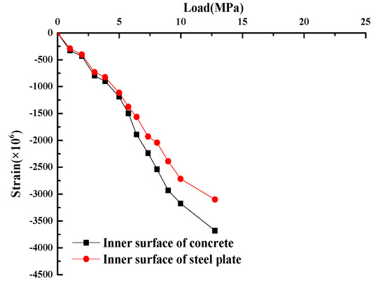
Figure 5.
Load–hoop strain curves of model ZJ1.
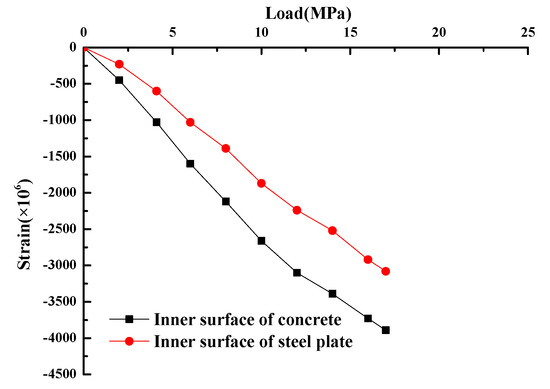
Figure 6.
Load–hoop strain curves of model ZJ4.
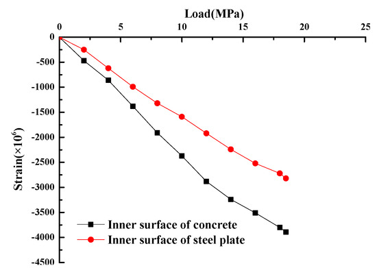
Figure 7.
Load–hoop strain curves of model ZJ6.
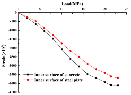
Figure 8.
Load–hoop strain curves of model ZJ8.
The following characteristics can be observed from the load–strain curves of the specimens in the whole loading process shown in Figure 5, Figure 6, Figure 7 and Figure 8.
At the initial stage of loading, due to the small load, the hoop strains of the steel plate and concrete composing the shaft lining structure were each linearly correlated to the load. In addition, changes in the strains of the concrete and steel plate were found to display essentially consistent trends. This stage could be viewed as the elastic stage of the shaft lining. The ultimate elastic load of the shaft lining was approximately 30%–40% of the failure load.
As the external load continued to increase, a linear relationship no longer applied between the hoop strain of the steel plate and the load and between the hoop strain of the concrete layer and the load; instead, an increasingly pronounced nonlinear relationship was observed, and the strain increment increased. In addition, the strain of the steel plate increased much faster than did that of the concrete. At this time, the shaft lining entered the plastic stage. As a result of the combined action of the inner and outer steel plates and the intermediate concrete layer, the deformation of the two was mutually constrained, resulting in a significant increase in the plastic deformation of the shaft lining. In particular, the inner and outer steel cylinders constrained the concrete layer, and consequently, its plastic properties became increasingly pronounced. Before the failure of the shaft lining, the hoop strains of the specimens ZJ1, ZJ4, ZJ6, and ZJ8 reached −3106 με, −3070 με, −2820 με, and −3680 με, respectively, corresponding to an increase in the toughness of the composite shaft lining and, therefore, an improvement in its safety.
5.2. Stress Characteristics of the Shaft Lining Model
The strain measurements obtained during the loading process were converted to stress values using the experimental stress analysis method. On this basis, the load–stress curves of the specimens were plotted. Figure 9, Figure 10, Figure 11 and Figure 12 show the load–hoop stress curves of the steel plates and concrete layers contained in specimens ZJ1, ZJ4, ZJ6, and ZJ8, respectively.
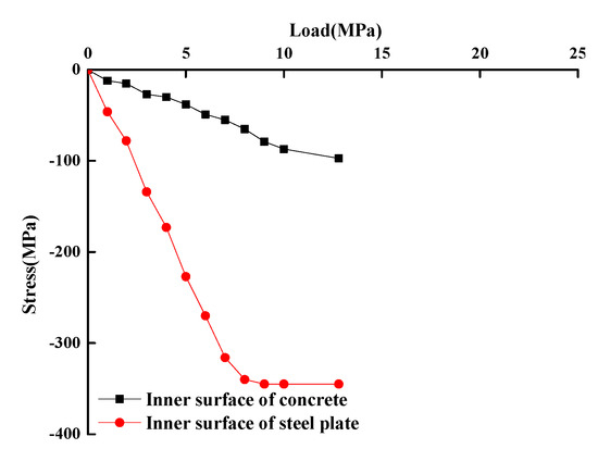
Figure 9.
Load–hoop stress curve of specimen ZJ1.
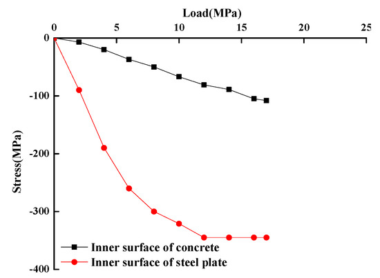
Figure 10.
Load–hoop stress curve of specimen ZJ4.
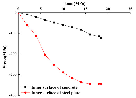
Figure 11.
Load–hoop stress curve of specimen ZJ6.
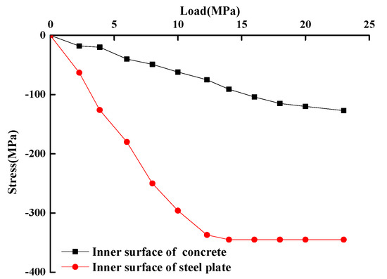
Figure 12.
Load–hoop stress curve of specimen ZJ8.
As demonstrated in Figure 9, Figure 10, Figure 11 and Figure 12, when the load was small, the shaft lining structure displayed well-behaved linear elastic characteristics. The stress on the steel plate and the concrete layer both increased nearly linearly as the load increased. As the external load increased, the stress increased at an increasing rate, deviating from the linear pattern. Thus, the shaft lining structure entered the plastic stage. As the specimen entered the plastic deformation stage, the inner steel plate did not buckle and fail because of the anchoring action of the anchor clamps. The inner steel plate, together with the outer steel plate, strongly constrained the concrete layer between them and prevented this layer from undergoing deformation or crack initiation. As a result, the compressive strength of the concrete increased significantly, and this material displayed notable plastic properties [30]. Compared with the test results of the other shaft lining models, a similar change rule of stress was shown.
By analyzing Figure 9, Figure 10, Figure 11 and Figure 12, we observed that the maximum hoop stress on the shaft lining concrete in the specimens ZJ1, ZJ4, ZJ6, and ZJ8 reached 97.3 MPa, 108.0 MPa, 122.6 MPa, and 132.7 MPa, respectively, during the loading process until failure, much higher than the compressive strength determined from cube tests performed on the concrete used to fabricate the specimens (61.7 MPa, 60.2 MPa, 70.6 MPa, and 65.8 MPa, respectively). This finding suggests that the concrete in this type of shaft lining structure is under triaxial compressive stress and, consequently, that its actual compressive strength is significantly higher than its uniaxial strength. This type of composite shaft lining structure is enhanced by this mechanism.
5.3. Bearing Capacity of the Shaft Lining Model
Table 3 summarizes the failure loads for the specimens of the shaft lining model. The thin specimens of the steel-plate-confined high-performance composite concrete shaft lining model each had a high bearing capacity and therefore provided reasonable support for the large-diameter drill shaft.
Table 3.
Model specimen loading results.
To analyze the strength improvement coefficient of this type of composite shaft lining structure, based on the limit equilibrium conditions and the concrete strength theory, an equation for calculating the ultimate bearing capacity (Pb) was established:
where m is the compressive strength improvement coefficient of the concrete, Ra is the axial compressive strength of the concrete, Re is the lower yield point strength of the steel plates, b is the outer radius of the shaft lining, h is the thickness of the shaft lining, and hgn and hgw are the thicknesses of the inner and outer steel plates, respectively.
Table 3 summarizes the compressive strength improvement coefficients of the concrete in the composite shaft lining structure calculated using Equation (4) based on the test values of the bearing capacity. As demonstrated in Table 3, due to the constraints exerted by the inner and outer steel plates, the concrete layer in this shaft lining structure was under triaxial compression and, consequently, its compressive strength increased significantly by a factor of 1.97–2.52. This result is consistent with the results reported by researchers in China and elsewhere on the improvement of the compressive strength of concrete under compressive stresses [31,32,33,34]. In addition, the values of the improvement coefficient also meet the requirements for the compressive strength improvement coefficient of concrete in the current standard of China [24], which suggests that this parameter should be taken into consideration in design calculations of this type of shaft lining structure to allow the structure to reflect its actual reliability.
Based on testing and theoretical analyses, factors affecting the compressive strength improvement coefficient (m) of concrete in this type of thin, high-performance shaft lining structure include the thickness of the shaft lining, the lower point yield strength and thickness of the steel plates (hg represents the sum of the thicknesses of the inner and outer steel plates), the inner diameter of the shaft lining (2a), and the compressive strength of the concrete layer (Ra). The expression of “m” can thus be determined by a dimensional analysis method using the data in Table 3 [35]:
The correlation coefficient of Formula (7) was represented by R2 (R2 = 0.942) and satisfied the requirement of relevance.
5.4. Failure Form of the Shaft Lining Model
When the model specimen was loaded to near failure, the inner steel plate began to deform due to obvious longitudinal yield between two local anchor clamps firstly. Then, the concrete part close to the deformed part of the inner steel plate changed from a triaxial state to a biaxial state. Thus, it caused failure of the concrete and the outer steel plate. Generally, the inner steel plate had a convex layer, the outer steel plate had a concave layer, and the middle concrete had compression–shear failure along the oblique section of the inner and outer steel plates in terms of buckling [36,37]. The failure form of the model is shown in Figure 13. It can be seen that the concrete was subjected to triaxial compression due to the effective restraint of the inner and outer steel plates on the concrete, which significantly improved the concrete strength [38,39]. For the anchor clamps welded to the inner steel plate, the middle concrete layer acted as an anchorage to the inner steel plate, preventing premature instability of the inner steel plate barrel and improving its bearing capacity. The composite effect of the steel plates and concrete improved the bearing capacity of the structure.
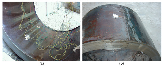
Figure 13.
Failure form of the shaft lining model: (a) inner surface (b) outer surface.
When the shaft lining models were loaded to near failure, the inner steel plate was unstable due to obvious longitudinal yield; it can be seen from Figure 13 that a plastic yield surface appeared in the inner and outer steel plates and compression–shear failure appeared in the concrete between the two steel plates. Due to the operative constraint from steel plates, the brittleness of the concrete was weakened but the plasticity was enhanced significantly. The failure form was obviously different from that of concrete under uniaxial compression. This showed that the composite action of steel plates and concrete gave the shaft lining model excellent ductility characteristics.
6. Engineering Application
Following design optimization based on the aforementioned test results, the construction parameters for the dual-steel-plate-confined high-performance concrete shaft lining structure for the intake shaft in the west zone of Zhangji coal mine were determined: the thickness of the shaft lining at the vertical depth range of 378–435 m was 800 mm, the thickness of the inner steel plate was 20 mm, the thickness of the outer steel plate was 16 mm, and the concrete strength grade was C65. The shaft lining in the control layer was no thicker than 800 mm, thereby ensuring that the shaft could be constructed using the drilling method.
According to the drill shaft lining design theory, the shaft lining could withstand 4.815 MPa of pressure from water and soil at the bottom of the alluvial strata at a depth of 401.22 m. The test results in Figure 14 show that the hoop stress on the inner side of the concrete in the dual-steel-plate-confined high-performance composite concrete shaft lining structure was only approximately 28 MPa (only 1/4 of the ultimate stress for the concrete) under a load of 4.815 MPa. This finding indicates that the concrete in the dual-steel-plate-confined high-performance composite concrete shaft lining structure has a considerably higher compressive strength and is in an elastic state under normal working loads; consequently, the shaft lining structure is safe and reliable.
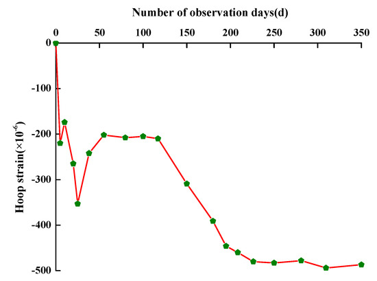
Figure 14.
Hoop strain of the shaft lining concrete in the field over time.
Based on the engineering geological conditions and construction drawing, an AS-9/500 drilling rig equipped with a gantry crane with a hoisting capacity of 2000 kN was selected to hoist the drilling equipment and prefabricated shaft lining. During construction, a four-stage reaming and drilling scheme was adopted to produce a drilling diameter of 10.8 m. Subsequently, the shaft lining was sunk by flotation, and then the gap between the lining and the surrounding soil was filled. The project was completed without incident. The constructed shaft had a tilt ratio of only 0.252‰, was not immersed in water, and was of excellent quality. This shaft (net diameter: 8.3 m) set a record for the largest-diameter shaft ever constructed using mine shaft drilling in China or elsewhere.
The design parameters of the shaft lining were optimized based on the test results. To understand its deformation in the control layer under stress in real time and evaluate its safety during operation, the deformation of the shaft lining structure was monitored under stress.
Field measurements were conducted using vibrating-wire sensors. A test site was set at the 20th section of the shaft lining (corresponding to the layer at a depth of 398.0 m). When fabricating this section of the shaft lining, concrete strain gauges were embedded, and the busbars of all the measuring components were placed in a recessed junction box, which was connected to a 35 mm2 core armored signal-shielding control cable when sinking the shaft lining by flotation. Real-time monitoring was performed on the ground.
Large amounts of field data were obtained from long-term monitoring. Figure 14 shows the measurements of the hoop strain of the concrete in the shaft lining.
Measurements began when the slurry submerged the layer where the measuring components were located after the 20th section of the shaft lining was sunk. Water (as needed) was added as a counterweight in real time when sinking the shaft lining. The sinking of the shaft lining was completed on the 20th day. At this time, the water in the shaft was 144 m from the opening. Starting on the 25th day, the gap between the shaft and the surrounding soil began to be filled to cement the shaft. This process was completed on the 38th day. Draining started on the 112th day and was completed on the 195th day. Subsequently, long-term observations were conducted.
As demonstrated in Figure 14, at the stage when the shaft lining was under normal stress conditions after the draining process, in the lower part of the intake shaft, the hoop strain of the concrete layer in the composite concrete shaft lining structure stabilized at approximately −487 με, far smaller than the ultimate strain of C65 concrete. This result suggests that the shaft lining was in an elastic working state under external loading, thereby demonstrating the safety and reliability of the optimized shaft lining structure design.
7. Conclusions
According to the basic principle of similarity model tests, a large-diameter composite shaft lining model test was reasonably designed. After practical engineering application and analysis of field measurements, the following main conclusions were obtained:
- (1)
- Under the hoop constraints of the inner and outer steel plate, the ultimate strain of the specimens of the dual-steel-plate-confined high-performance composite shaft lining structure reached −3106 με, −3070 με, −2820 με, and −3680 με, respectively, demonstrating that the brittleness of the concrete was improved considerably.
- (2)
- The model test results showed that the compressive strength of the concrete in the dual-steel-plate-confined high-performance composite concrete shaft lining structure for large-diameter drill shafts increased by a factor of 1.97–2.52, resulting in a considerable increase in its bearing capacity.
- (3)
- The model test results showed that the maximum thickness of the dual-steel-plate-confined high-performance composite concrete shaft lining structure could be 800 mm to satisfy the safety requirements of the control layer of the intake shaft in the west zone of Zhangji coal mine. In the end, the project was recognized as a new record for constructing a large-diameter shaft using the drilling method.
- (4)
- The field measurement data showed that the hoop strain of the concrete layer in this new type of shaft lining structure was −487 με, far smaller than the ultimate strain of C65 concrete. This result demonstrates that this shaft lining structure is safe and reliable under typical working loads.
The main purpose of the study was to solve the engineering technical problem of a shaft lining with large diameter using the drilling method. Next, we will systematically study the influence of factors such as the diameter and thickness of the shaft lining, the thickness of the outer and inner steel plate, strength of concrete, and size of the anchor by combining numerical calculations and model testing, so as to find the optimal design parameters. In future research, optical fiber sensors and other advanced test elements will be used to monitor the strain of the shaft lining model. Then, the stress and deformation characteristics of the cross section of the shaft lining model will be analyzed systematically, and the mechanical mechanism will finally be revealed completely.
Structural model testing is a research method used to solve support problems in underground engineering. Usually, the geometric similarity ratio is 5–20. The larger the similarity ratio, the larger the size effect error. However, when the geometric similarity is small and the model specimen is large, the error is usually within the allowable range for engineering. The geometric similarity ratio of the shaft lining model test was 10.7, which belonged to a larger structure model, so the test error was small. In future research, experimental research with different similarity ratios should be carried out to obtain the size effect rule.
Author Contributions
Conceptualization, Z.Y. and P.Z.; methodology, Z.Y.; software, W.X.; validation, Z.Y., H.C. and W.X.; formal analysis, X.L.; investigation, P.Z.; resources, H.C.; data curation, W.X.; writing—original draft preparation, P.Z.; writing—review and editing, Z.Y.; visualization, X.L.; supervision, Z.Y.; project administration, W.X.; funding acquisition, H.C. All authors have read and agreed to the published version of the manuscript.
Funding
This research was supported by the Anhui University discipline professional talented person (No. gxbjZD09), the Science Research Foundation for Young Teachers in Anhui University of Science and Technology (QN201710), and Anhui Provincial College of Natural Science Research Key Project (KJ2018A0098).
Conflicts of Interest
The authors declare no conflict of interest.
References
- Cui, Y.L. A Concise Handbook of Mine Construction Engineering; China Coal Industry Press: Beijing, China, 2003; pp. 1423–1429. [Google Scholar]
- Yang, R.S.; Chen, J. Development status and prospects of mine shaft construction equipment and technology. Mine Constr. Tech. 2015, 36, 1–4. [Google Scholar]
- Liu, Z.Q. Development and prospect of mechanical shaft boring technology. J. China Coal Soc. 2013, 38, 1116–1122. [Google Scholar]
- Chinese Standard GB50384-2007. China Coal Construction Association. In Code for Design of Coal Mine Shaft and Chamber; China Planning Press: Beijing, China, 2007. (In Chinese) [Google Scholar]
- Zhang, R.L.; He, G.W.; Li, D. Designing Guidebook of Coal Mining; China Coal Industry Press: Beijing, China, 2002; pp. 1743–1751. [Google Scholar]
- Wang, C.; Yang, C.H.; Liu, F.; Wan, C.J.; Pu, X.C. Preparation of ultra-high performance concrete with common technology and materials. Cement Conc. Compos. 2012, 34, 538–544. [Google Scholar] [CrossRef]
- Abdulkareem, O.M.; Ben, F.; Amor Bouasker, M.; Khelidj, A. Mixture design and early age investigations of more sustainable UHPC. Cons. Build. Mater. 2018, 163, 235–246. [Google Scholar] [CrossRef]
- Zhang, Y.C. Drilling Construction Guidebook; China Coal Industry Press: Beijing, China, 2010. [Google Scholar]
- Du, H.; Zhang, B.; Hu, X.; Kou, L.; Xia, Y. Experimental study on shear behavior of bolt connectors in steel-concrete composite beams. J. Build. Struct. 2017, 38, 308–314. [Google Scholar]
- Chen, J.; Wang, W.; Ding, F.X.; Xiang, P.; Yu, Y.J.; Liu, X.M.; Xu, F.; Yang, C.Q.; Long, S.G. Behavior of an advanced bolted shear connector in prefabricated steel-concrete composite beams. Materials 2019, 12, 2958. [Google Scholar] [CrossRef]
- Ling, Y.H.; Zheng, Z.Y.; Yang, T.Y.; Ma, H.W. Behavior and modeling of the bearing capacity of shear stud connectors. Intern. J. Steel Struc. 2019, 19, 650–659. [Google Scholar] [CrossRef]
- Huang, Z.Y.; Liew, J.Y.R. Steel-concrete-steel sandwich composite structures subjected to extreme loads. Intern. J. Steel Struc. 2016, 16, 1009–1028. [Google Scholar] [CrossRef]
- Liew, J.Y.R.; Yan, J.B.; Huang, Z.Y. Steel-concrete-steel sandwich composite structures-recent innovations. J. Constr. Steel Res. 2017, 130, 202–221. [Google Scholar] [CrossRef]
- Chin, C.L.; Ma, C.K.; Tan, J.Y.; Ong, C.B.; Awang, A.Z.; Omar, W. Review on development of external steel-confined concrete. Cons. Build. Mater. 2019, 211, 919–931. [Google Scholar] [CrossRef]
- Hong, B.Q. The research and application of confined concrete structure in shaft lining. J. China Coal Soc. 2002, 25, 150–154. [Google Scholar]
- Wang, C. Study on the Mechanical Characteristics of Bored Shaft Lining Consisting of Inner Steel Sheet and Reinforced Concrete in 600m Thick Alluvium; China Coal Research Institute: Beijing, China, 2003; pp. 19–61. [Google Scholar]
- Hong, B.Q.; Zang, G.M.; Tao, J. Design and installation of sidewall of 600 m deep well in Longgu mine. China Coal 2004, 6, 9–12. [Google Scholar]
- Qi, S.Z.; Yang, W.H. Study of mechanical characteristics of high strength steel fiber reinforced concrete shaft lining with inner steel plate. Coal Eng. 2011, 48, 103–106. [Google Scholar]
- Yao, Z.S.; Rong, C.X. Numerical simulation on strength of composite shift lining of high strength concrete and double steel cylinder. J. Liaoning Tech. Univ. 2004, 23, 321–323. [Google Scholar]
- Zhang, C.; Wang, X.Q.; He, F.G.; Lin, J.H. Numerical simulation on mechanical characteristics of confined concrete drilling shift lining of double steel plate. Mine Const. Technol. 2008, 29, 22–24. [Google Scholar]
- Cai, H.B.; Cheng, H.; Huang, Y.C. Study on mechanical characteristic of two-layer steel plate concrete shaft lining under non uniform pressure. Appl. Mech. Mater. 2013, 351–352, 17–21. [Google Scholar] [CrossRef]
- Wei, X.X.; Lai, Y.M. Theory and Application of Similar Method; Lanzhou University Press: Lanzhou, China, 2001. [Google Scholar]
- Yang, J.J. The Similarity Theory and Structural Model Test; Wuhan University of Science and Technology Press: Wuhan, China, 2005; pp. 15–26. [Google Scholar]
- Chinese Standard GB50010-2010. China Ministry of Housing and Urban-Rural Development. In Code for Design of Concrete Structures; China Architecture and Building Press: Beijing, China, 2013. (In Chinese) [Google Scholar]
- Chinese Standard GB50017-2017. China Ministry of Housing and Urban-Rural Development. In Standard for Design of Steel Structures; China Architecture and Building Press: Beijing, China, 2017. (In Chinese) [Google Scholar]
- Yao, Z.S.; Chen, H.; Song, H.Q. Preparation and application of high strength and high performance concrete of drilling shaft lining in special deep alluvium. China Min. Mag. 2007, 16, 77–79. [Google Scholar]
- Chinese Standard JGJ55-2011. China Ministry of Housing and Urban-Rural Development. In Specification for Mix Proportion Design of Ordinary Concrete; China Architecture and Building Press: Beijing, China, 2011. (In Chinese) [Google Scholar]
- Chinese Standard GB/T50081-2002. China Academy of Building Research. In Standard for Test Method of Mechanical Properties on Ordinary Concrete; China Architecture and Building Press: Beijing, China, 2003. (In Chinese) [Google Scholar]
- Chinese Standard GB/T228—2010. China Steel Research Institute. In Metallic Materials—Tensile Testing—Part 1: Method of Test at Room Temperature; China Standard Press: Beijing, China, 2011. (In Chinese) [Google Scholar]
- Li, H. High Strength Concrete and Composite Structure; Science Press: Beijing, China, 2004. [Google Scholar]
- Guo, Z.H. Principle and Application of the Concrete Strength and Constitutive Relationship; China Architecture and Buildings Press: Beijing, China, 2004. [Google Scholar]
- Song, Y.P. The Constitutive Relationship and Failure Criterion of Concrete under Multi-Axial Stresses; China Water Power Press: Beijing, China, 2002. [Google Scholar]
- O’Shea, M.D.; Bridge, R.Q. Design of Circular Thin-Walled Concrete Filled Steel Tubes. J. Struc. Eng. 2000, 126, 1295–1303. [Google Scholar] [CrossRef]
- Luo, D.N.; Li, Q.B.; Hu, Y.; Chen, T. Strength criterion for high-strength concrete based on the unified strength theory. J. Hydra. Eng. 2015, 46, 74–82. [Google Scholar]
- Yao, Z.S.; Zhao, L.X.; Chen, H.; Xu, H.S. Optimization design and measurement analysis on inter lining of high strength reinforced concrete frozen shaft lining with deep topsoil. J. China Coal Soc. 2019, 44, 2125–2132. [Google Scholar]
- Song, Y.P.; Wen, W.; Wang, H.L. Analysis on compression-shear strength of roller compacted concrete. J. Water Res. Arch. Eng. 2012, 6, 46–49. [Google Scholar]
- Liu, J.H. Application of Compression-Shear Strength of Steel Fiber Reinforced Concrete in the Design of Tunnel Lining; Southwest Jiaotong University: Chengdu, China, 2006. [Google Scholar]
- Bažant, Z.P.; Pfeiffer, P.A. Shear fracture tests of concrete. Mater. Struc. 1986, 19, 111. [Google Scholar] [CrossRef]
- Yu, Z.P.; Huang, Q.; Xie, X.H.; Xiao, N. Experimental study and failure criterion analysis of plain concrete under combined compression-shear stress. Constr. Build. Mater. 2018, 179, 198–206. [Google Scholar] [CrossRef]
© 2020 by the authors. Licensee MDPI, Basel, Switzerland. This article is an open access article distributed under the terms and conditions of the Creative Commons Attribution (CC BY) license (http://creativecommons.org/licenses/by/4.0/).