Abstract
This paper proposes the application of an adjustable speed diesel engine-driven power plant employing a doubly-fed induction generator to an isolated small-scale power system including renewable power sources. This type of power plant can contribute to fast and flexible power balancing regulation under vacillating power supply such as wind, solar and other renewable power sources. Installation of a battery system is also considered, which can assist in coordinating the power plant to augment renewable power sources in the isolated power system.
1. Introduction
There are many small islands with residential areas in which power systems are often small-scale and isolated. In most cases, electrical power sources in such power systems are supplied from diesel engine-driven power plants. However, such plants have a negative environmental impact. Therefore, effective utilization of renewable power on islands is a crucial matter because there are often abundant wind energy sources there. However, because of vacillating renewable power due to dependence on weather conditions, the electricity quality of small-scale power systems with renewable power sources may decline. Hence, even a small amount of renewable power sources may not be introduced. Against this background, various design methods of microgrids, which include diesel power plants, energy storage systems and renewable energy sources, have been proposed that consider various viewpoints. Most of these studies are premised on the utilization of energy storage devices, and stabilization control studies using batteries for the balance between supply and demand in the microgrid have also been reported [1,2,3,4,5,6]. In some cases, flywheel energy storage systems are introduced into diesel power generator-based microgrids instead of chemical batteries [7,8].
The problem which requires an energy storage device can be significant if the main electrical power source is supplied by a conventional fixed speed synchronous generator (FS-SG). According to such situations, several kinds of strategies focusing on the main generator operation have been reported to regulate a microgrid system incorporating renewable power sources [9,10,11]. Most of these systems are composed of a conventional synchronous generator driven by a diesel engine as the main power source, and an energy storage system is considered in some cases. On the other hand, if the main generator can control its output quickly, then a balance between the generation and consumption in the power system will be effectively maintained. Under such consideration, applications of an adjustable speed diesel generator have been proposed in several reports [12,13,14]. However, there are few reports that provide detailed analyses of a small power system composed of a diesel power plant and a wind power station as a renewable power source, as well as their cooperative control system performed under natural variable wind conditions. In this paper, a new control strategy for the design and operation of a small-scale power system is proposed in order to improve its frequency stability against vacillating power from a wind power station. A diesel engine driven adjustable speed generator (ASG) employing a doubly-fed induction generator (DFIG) and a cooperatively controlled battery are adopted. In our previous reports [15,16], we presented that frequency stabilization can be achieved effectively by the installation of an ASG. As only two profiles of fluctuating power were considered there; however, the effectiveness of the ASG control was not sufficiently evaluated. Moreover, in these reports, a conventional proportional–differential (PD) controller with fixed control parameters was applied to the frequency stabilization by using the ASG. Therefore, it was unclear whether the ASG could sufficiently regulate the grid frequency under the variations of the fluctuating power or not. This was because the conventional PD controller with fixed gains could not always achieve excellent performance under various conditions of the controlled system. Accordingly, in this study, a fuzzy logic control based PD controller was applied to the frequency control system by using the ASG. In general, fuzzy logic control is robust and can be expected to achieve sufficient performance under a variety of controlled system conditions, such as randomly fluctuating power from renewable power sources. In addition, as it is expected that more batteries will be introduced into power systems in the future, the battery energy storage system (BESS) is also considered in this paper, and a cooperative frequency control system with an ASG is designed. In this paper, to evaluate the validity of the proposed cooperative control, a degree of the smoothing effect of system frequency is investigated by simulation analyses with respect to various conditions of the small-scale power system, and then a possible amount of wind power installation is assessed. The simulation analysis is carried out using the PSCAD/EMTDC simulation program.
2. Overview of the System and Its Modeling
2.1. Topology of the Small-Scale Power System
Though there are a lot of topologies in small-scale power systems, an isolated small-scale power system model, which represents an island with residential areas, is used in this paper (shown in Figure 1). DG1 and DG2 are thermal power plants driven by diesel engines. DG1 is a fixed speed synchronous generator (FS-SG) equipped with a speed governor and an automatic voltage regulator. DG2 is assumed to include two types of generators in this study. One is the same type as DG1 with the role of conventional FS-SG, and the other is an adjustable speed generator (ASG) that employs a doubly-fed induction generator (DFIG), which is the new strategy proposed in this paper for a small-scale power system. The difference between the performances of the two types of generators for DG2 is evaluated from the point of view of stabilization of the power system frequency fluctuation. The wind power station is modeled as a single permanent magnet synchronous generator equipped with a power converter and aerodynamic variable speed wind turbine. Loads A and B represent a consumer and are modeled using constant impedance components. Rated voltage at each node and impedance of each transmission line and transformer are shown in Figure 1, but the power rating of generators is not indicated because several combinations of generator power rating are considered in this study. However, the total capacity of DG1 and DG2 is fixed to 10 MVA. The impedance of each transformer is based on the self-capacity base. The parameters of the power plants and loads are shown in Table 1.
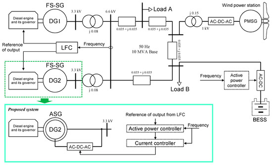
Figure 1.
Model of small-scale power system.

Table 1.
Parameters of power plant and loads.
2.2. Model of the Diesel Engine Driven Power Plant
The speed governor and torque output model shown in Figure 2 is used for diesel engine-driven power plants DG1 and DG2, respectively. Several types of diesel engine and governor models have been presented; however, an uncomplicated model is adopted in this study [17,18]. The speed governor regulates the power of the diesel engine so as to keep its speed at a preset reference speed. In the case of an FS-SG generator, it is essentially controlled by a governor free mode with droop characteristics. In the case of ASG, the speed governor should control the varying speed to return it back to the preset reference more precisely; therefore, PID controller is used. The range of torque output of the diesel engine is limited, in general, between 50% and 100%, which is a typical range from the point of view of fuel cost and the lifetime of the diesel engine. Moreover, in consideration of mechanical stress reduction of the engine, the rate of change of the torque output also needs to be limited to 90%/minute, for example. Parameters of the model are expressed in Table 2, and machine parameters of the conventional FS-SG are expressed in Table 3.
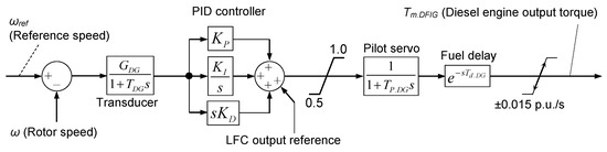
Figure 2.
Speed governor and torque output model of a diesel engine.
Table 2.
Parameters of the diesel governors.
Table 3.
Electrical parameters of the fixed speed synchronous generator (FS-SG).
In addition to the governor free control, the outputs of DG1 and DG2 are also regulated by load frequency control (LFC), which maintains a balance between the power demand and consumption over more than several minutes. The LFC configuration is shown in Figure 3. Output commands for LFC are distributed to DG1 and DG2 in accordance with a ratio of power rating of each generator.
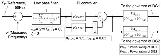
Figure 3.
Model of a load frequency control (LFC).
Figure 4 shows the model of automatic voltage regulator installed in FS-SG. Figure 5 shows a fundamental structure of the adjustable speed generator (ASG), which consists of a doubly-fed induction generator (DFIG) and its AC excitation control. This system has an advantage in that active and reactive power can be controlled independently. Moreover, only a partial power rating of the electronic power converter is needed, which corresponds to the maximum slip from the synchronous speed. In this study, the reactive power is regulated to maintain a constant terminal voltage of the ASG. The active power of the ASG can be utilized in response to power system frequency behavior, as explained in Section 3. The speed governor of DG2 in the case of ASG is basically the same as in Figure 2, while the reference speed is set to 1.044 pu, at which the controllable kinetic energy is halved. In this study, the adjustable speed range of the ASG is from 0.7 to 1.3 pu (thus, the power converter capacity is 30% of the ASG power rating), and controllable kinetic energy is regarded as 0% when the speed is minimum (0.7 pu) and is 100% when the speed is maximum (1.3 pu). The controllable kinetic energy becomes 50% at the speed of 1.044 pu, as expressed in Equation (1). The machine parameters of the DFIG are shown in Table 4.
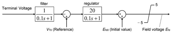
Figure 4.
Automatic voltage regulator for the conventional FS-SG.
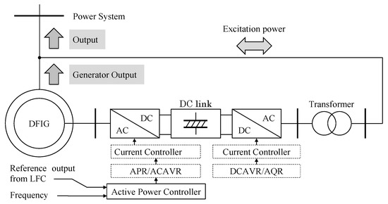
Figure 5.
Overview of the adjustable speed generator (ASG) and its control system.
Table 4.
Electrical parameters of the doubly-fed induction generator (DFIG) as the ASG.
2.3. Model of Battery Energy Storage System (BESS)
In this study, it is assumed that a battery energy storage system (BESS) is installed at the connection point of Load B, as shown in Figure 1, and additional regulation by the battery charging/discharging control for the system frequency is triggered for a limited time when steep frequency fluctuation occurs so that the ASG cannot regulate sufficiently. The BESS is simulated by using an ideal voltage source without considering any power consumption or the chemical characteristics of the battery. The power of the BESS is determined according to the explanation provided in Section 4.
2.4. Model of the Wind Power Station
The single wind generator in the wind power station consists of a permanent magnet synchronous generator (PMSG), AC-DC-AC power converter and a wind turbine, of which aerodynamical characteristics are expressed as follows in Equations (2)–(5) [19]. The speed of the wind turbine is controlled by a pitch angle controller, as shown in Figure 6, which is operated when the speed exceeds the rated speed. The output of the PMSG is regulated according to the maximum power point tracking (MPPT) characteristics. Table 5 shows the machine parameters of the PMSG.
where Pwtb is the output of the wind turbine (W), λ is the tip speed ratio, R is the length of the turbine blade (m), ωwtb is the speed of the wind turbine (rad/s), ρ is the air density (kg/m3), β is the pitch angle of the turbine blade (deg) and Vw is the wind speed (m/s).
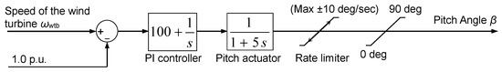
Figure 6.
Pitch angle controller of the variable speed wind turbine.
Table 5.
Electrical parameters of the permanent magnet synchronous generator (PMSG).
3. Active Power Control of the ASG to Suppress Frequency Fluctuation
When the ASG is adopted as DG2, ASG controls its output power in order to suppress the frequency fluctuations of the power system. In this study, the DFIG is adopted as the ASG, and a fuzzy logic controller is installed for generating the reference of DFIG active power, as shown in Figure 7. Due to the installation of the fuzzy logic controller, it is expected that the frequency control system can achieve sufficient performance under a variety of controlled power system conditions, such as randomly fluctuating power from the wind farm. Though there are several fuzzy logic control methods, Takagi–Sugeno fuzzy logic is adopted in this study [20]. Measured frequency deviation ΔF and its differential value are used for fuzzy logic control, and the reference for DFIG active power is calculated by using the fuzzy rule shown in Table 6 and the membership function shown in Figure 8a,b. Parameters shown in Figure 7 and Figure 8 and Table 6 have been determined by trial and error method. Specifically, the gains GP, GD and GO shown in Figure 7, and the values on the horizontal axes in the membership functions shown in Figure 8a,b have been repeatedly employed in various patterns, and the values making the system response more stable (i.e., non-oscillatory) and improving the frequency fluctuation suppression effect have been selected. Moreover, when the DFIG rotor speed approaches its limit, speed change will be restrained by correcting the reference. This process is shown in Figure 9, from which it is seen that, when the kinetic energy of the DFIG becomes less than 45%, an additional negative value for correcting the reference, PDFIG_correc, is added in order to decrease the output of the DFIG. On the other hand, when the kinetic energy of the DFIG becomes greater than 60%, a positive PDFIG_correc is added in order to increase the output of the DFIG. In this way, the threshold values and slopes are kept within the permissible range.
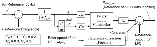
Figure 7.
Active power controller of the DFIG as the ASG.
Table 6.
Fuzzy rules of the fuzzy logic controller of the DFIG.
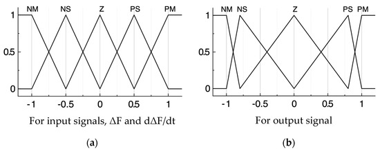
Figure 8.
Membership function of the fuzzy logic controller of the DFIG.
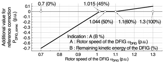
Figure 9.
Reference correction of the DFIG active power depending on its rotor speed.
4. Cooperative Control of BESS
It is well known that a battery system can contribute well to suppressing power system frequency fluctuations. In this study, it is assumed that a battery energy storage system (BESS) is installed near the consumer and can be regulated so as to suppress frequency fluctuations in cooperation with the ASG. Though a lot of schemes have been proposed for BESS power control, fuzzy logic control is adopted in this study, as shown in Figure 10. The design concept of the battery controller is the same as that of the ASG. According to frequency deviation, output power reference is calculated based on the fuzzy control parameters shown in Figure 11 and Table 7. However, the control gain for the input signal and the membership function of the fuzzy control system in the BESS are different from those of DFIG and are tuned to behave cooperatively to further enhance the effectiveness of the control by DFIG. The fuzzy control contains differential operations in order to respond quickly to fast changes in the frequency. This scheme of control is basically the same as the control scheme of the ASG, but the roles of BESS and ASG are shared by the setting of different control gains, as mentioned above.
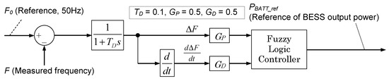
Figure 10.
Active power controller of the battery energy storage system (BESS).
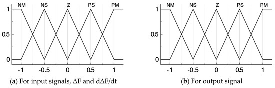
Figure 11.
Membership function of the fuzzy logic controller of the BESS.
Table 7.
Fuzzy rules of the fuzzy logic controller of the BESS.
5. Simulation Analysis
5.1. Simulation Settings
In order to evaluate the efficacy of the proposed approach to suppress the frequency fluctuations in a small-scale power system by the adjustable speed diesel engine-driven generator, system behavior under vacillating power from a wind power station in the power system was analyzed. Wind speed data, which was a measured record of the real wind in Hokkaido, Japan, was applied to the simulation analysis. This was because it was important to assess the performance of the proposed approach under a situation of natural wind conditions where the ability of the adjustable speed diesel engine-driven power plant to stabilize the power system frequency could be evaluated. Nine profiles of wind power obtained from the natural wind conditions were used in the simulation analysis (shown in Figure 12) and were referred to as Wind No.1 to 9. The wind speed data used in each profile was for 1 h, with a 1 s interval, and the resultant wind power had various different average levels and different vacillating levels corresponding to standard deviation (shown in Figure 12). Simulation analyses for four cases performed in this paper for the combination of two diesel generators are shown in Table 1. The rated capacity of the wind power station was set to 0.5 MW. This was based on the ideal range of controllable output of the ASG in Case 2 of Table 1. Though the rated output of the ASG in Case 2 was 2.5 MW, the actual output should have been within the range from 1.25 (50%) to 2.5 MW (100%) due to the limited range of the diesel engine output. In this situation, when the ASG output was 1.875 MW (75%), the center of the output range, then the ASG could provide ideal control, i.e., increase or decrease the output within ±0.625 MW (±25%). However, since the output correction (shown in Figure 9) was included in the control system, the ASG could hardly output the power near the upper limit (0.625 MW). Therefore, the rated output of the wind power station was set to 80% of 0.625 MW temporarily (thus, it was 0.5 MW). The power consumption of Load A and B were both 3.75 MW (75% of the power system capacity).
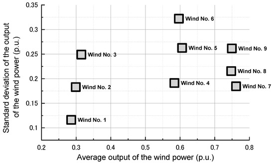
Figure 12.
Profiles of the wind power station output.
5.2. Simulation Results 1—Effect of the ASG Installation
Figure 13 shows the calculated standard deviations of the fluctuating frequency of the power system in Case 1 to Case 4 under nine wind generator output profiles. The BESS assistance is not considered. It can be seen that the frequency fluctuation can effectively be reduced in the proposed method (Case 2 to Case 4) compared to the conventional case (Case 1). In the case of Winds No.6 and 9, frequency fluctuations are large, but when half of the power generation is supplied from the ASG, the fluctuations can be reduced to about half of that in Case 1. Figure 14 shows the standard deviation of the varying rotor speed of the ASG. It can be seen that the larger the power rating of the ASG, the smaller the rotor speed variation of the ASG.
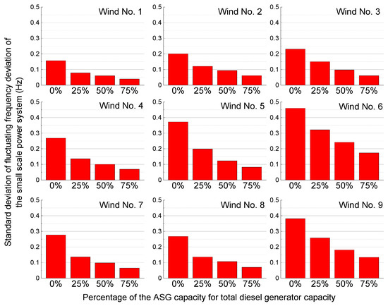
Figure 13.
Standard deviation of the power system frequency.
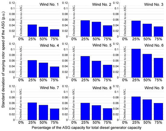
Figure 14.
Standard deviation of the rotor speed of the ASG.
5.3. Simulation Results 2—Effect of the Additional BESS Assisting
The effect of the BESS assisting the ASG control explained in Section 4 is evaluated in this section. The BESS controls its power to suppress the power system frequency fluctuation directly. Simulation results for the case of Wind No.6 are presented here because its fluctuation level is highest, as shown in Figure 12. The left part of Figure 15 shows the standard deviation of the power system frequency. As shown in Figure 15, power system frequency fluctuations can be suppressed more effectively than the case with only the ASG. Maximum battery power is also shown in the center part of Figure 15. Even when all of the diesel generators are conventional FS-SG, the BESS exhibits good performance. However, a larger BESS capacity will be needed. As the ASG capacity increases, the maximum output of the BESS decreases, and thus the power capacity of the BESS can be reduced. The right part of Figure 15 shows the standard deviation of the varying rotor speed of the ASG. It becomes smaller in the case where BESS is installed. It can also be said that the mechanical stress of the ASG can be reduced. Therefore, it can be concluded that the proposed combined control of the ASG and the BESS is very effective for stabilizing power system frequency fluctuations.
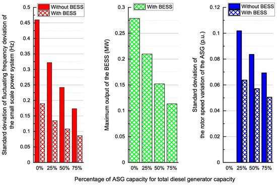
Figure 15.
Standard deviation of the power system frequency, maximum power of the BESS and rotor speed variation of the ASG.
6. Conclusions
In this paper, the adjustable speed generator (ASG) is proposed for diesel engine-driven power plants to stabilize the frequency fluctuations of a small-scale power system, and its performance is evaluated through simulation analyses by using natural wind conditions. In addition to the employment of the ASG in the diesel power plant, the battery energy storage system (BESS) is also proposed to support the frequency control of the ASG. Additionally, a fuzzy logic controller is installed into the ASG and BESS control systems to realize flexible and cooperative control against a large variety of fluctuating power.
The simulation results show that the proposed ASG can regulate the frequency fluctuations of the small-scale power system efficaciously, and its control ability can be enhanced by adding the cooperative power regulation of the BESS. Consequently, it can be concluded that wind power utilization in an isolated small-scale power system can be augmented by employing the proposed coordinating control system of the ASG based diesel engine-driven power plant and the cooperation of the BESS.
Author Contributions
R.T. prepared the theoretical concept and simulation models, carried out simulations and evaluations, and wrote the manuscript. A.U. and J.T. evaluated the validity of the manuscript. All authors have read and agreed to the published version of the manuscript.
Funding
This study was supported by JSPS KAKENHI Grant-in-Aid for Scientific Research (C), Grant Number JP18K04099, from the Ministry of Education, Science, Sport and Culture of Japan.
Conflicts of Interest
The authors declare no conflict of interest regarding the publication of this paper.
References
- Yu, W.; Li, S.; Zhu, Y.; Yang, C.-F. Management and Distribution Strategies for Dynamic Power in a Ship’s Micro-Grid System Based on Photovoltaic Cell, Diesel Generator, and Lithium Battery. Energies 2019, 12, 4505. [Google Scholar] [CrossRef]
- Belila, A.; Benbouzid, M.; Berkouk, E.; Amirat, Y. On Energy Management Control of a PV-Diesel-ESS Based Microgrid in a Stand-Alone Context. Energies 2018, 11, 2164. [Google Scholar] [CrossRef]
- Worku, M.Y.; Hassan, M.A.; Abido, M.A. Real Time Energy Management and Control of Renewable Energy based Microgrid in Grid Connected and Island Modes. Energies 2019, 12, 276. [Google Scholar] [CrossRef]
- Moon, H.-J.; Kim, Y.-J.; Chang, J.-W.; Moon, S. Decentralised Active Power Control Strategy for Real-Time Power Balance in an Isolated Microgrid with an Energy Storage System and Diesel Generators. Energies 2019, 12, 511. [Google Scholar] [CrossRef]
- Chang, J.-W.; Lee, G.-S.; Moon, H.-J.; Glick, M.B.; Moon, S.-I. Coordinated Frequency and State-of-Charge Control with Multi-Battery Energy Storage Systems and Diesel Generators in an Isolated Microgrid. Energies 2019, 12, 1614. [Google Scholar] [CrossRef]
- Wu, Y.-K.; Tang, K.-T.; Lin, Z.K.; Tan, W.-S. Flexible Power System Defense Strategies in an Isolated Microgrid System with High Renewable Power Generation. Appl. Sci. 2020, 10, 3184. [Google Scholar] [CrossRef]
- Sebastián, R.; Pena-Alzola, R. Flywheel Energy Storage and Dump Load to Control the Active Power Excess in a Wind Diesel Power System. Energies 2020, 13, 2029. [Google Scholar] [CrossRef]
- Sakamoto, O.; Yamashita, K.; Kitauchi, Y.; Nanahara, T.; Inoue, T.; Arakaki, T.; Fukuda, H. Improvement of a voltage-stabilizing control system for integration of wind power generation into a small island power system. In Proceedings of the 2011 2nd IEEE PES International Conference and Exhibition on Innovative Smart Grid Technologies, Manchester, UK, 5–7 December 2011; pp. 1–7. [Google Scholar]
- Salazar, J.; Tadeo, F.; Prada, C. Modelling Of Diesel Generator Sets That Assist Off-Grid Renewable Energy Microgrids. J. Renew. Ener. Sustain. Dev. 2015, 1. [Google Scholar] [CrossRef]
- Torres, M.; Lopes, L.A.C. Inverter-Based Diesel Generator Emulator for the Study of Frequency Variations in a Laboratory-Scale Autonomous Power System. Energy Power Eng. 2013, 5, 274–283. [Google Scholar] [CrossRef]
- Chen, W.; Bazzi, A.M.; Hare, J.Z.; Gupta, S. Real-time integrated model of a micro-grid with distributed clean energy generators and their power electronics. In Proceedings of the 2016 IEEE Applied Power Electronics Conference and Exposition (APEC), Long Beach, CA, USA, 20–24 March 2016; pp. 2666–2672. [Google Scholar]
- Waris, T.; Nayar, C. Variable speed constant frequency diesel power conversion system using doubly fed induction generator (DFIG). In Proceedings of the 2008 IEEE Power Electronics Specialists Conference, Rhodes, Greece, 15–19 June 2008; pp. 2728–2734. [Google Scholar]
- Zhou, Z.; Camara, M.B.; Dakyo, B. Coordinated Power Control of Variable-Speed Diesel Generators and Lithium-Battery on a Hybrid Electric Boat. IEEE Trans. Veh. Technol. 2016, 66, 5775–5784. [Google Scholar] [CrossRef]
- Leuchter, J.; Rerucha, V.; Krupka, Z.; Bauer, P. Dynamic Behavior of Mobile Generator Set with Variable Speed and Diesel Engine. In Proceedings of the 2007 IEEE Power Electronics Specialists Conference, Orlando, FL, USA, 17–21 June 2007; pp. 2287–2293. [Google Scholar]
- Takahashi, R.; Umemura, A.; Tamura, J. An application of adjustable speed diesel power plant to frequency control of small scale power system with renewable energy sources. In Proceedings of the 2019 IEEE PES Asia-Pacific Power and Energy Engineering Conference (APPEEC), Macao, China, 1–4 December 2019. [Google Scholar]
- Takahashi, R.; Umemura, A.; Tamura, J. Stability Enhancement of Small-Scale Power Grid with Renewable Power Sources by Variable Speed Diesel Power Plant*. J. Power Energy Eng. 2020, 8, 1–17. [Google Scholar] [CrossRef]
- Roy, S.; Malik, O.P.; Hope, G.S. A k-Step Predictive Scheme for Speed Control of Diesel Driven Power Plants. IEEE Trans. Ind. Appl. 1993, 29, 389–396. [Google Scholar] [CrossRef]
- Ahmad, A.; Siddiqui, A.S. Modeling of A Wind Diesel Integrated System With No Storage. Int. J. Emerging Technol. Adv. Eng. 2014, 4, 106–112. [Google Scholar]
- Wasynczuk, O.; Man, D.T.; Sullivan, J.P. Dynamic Behavior of a Class of Wind Turbine Generators during Random Wind Fluctuations. IEEE Trans. Power Appar. Syst. 1981, 2837–2854. [Google Scholar] [CrossRef]
- Huang, D.; Nguang, S.K. Takagi–Sugeno Fuzzy Control System. Lect. Notes Control Inf. Sci. 2009, 386, 87–91. [Google Scholar] [CrossRef]
Publisher’s Note: MDPI stays neutral with regard to jurisdictional claims in published maps and institutional affiliations. |
© 2020 by the authors. Licensee MDPI, Basel, Switzerland. This article is an open access article distributed under the terms and conditions of the Creative Commons Attribution (CC BY) license (http://creativecommons.org/licenses/by/4.0/).