Energy Consumption Comparison of a Single Variable-Speed Pump and a System of Two Pumps: Variable-Speed and Fixed-Speed


 ,
,  , and
, and
Abstract
Featured Application
Abstract
1. Introduction
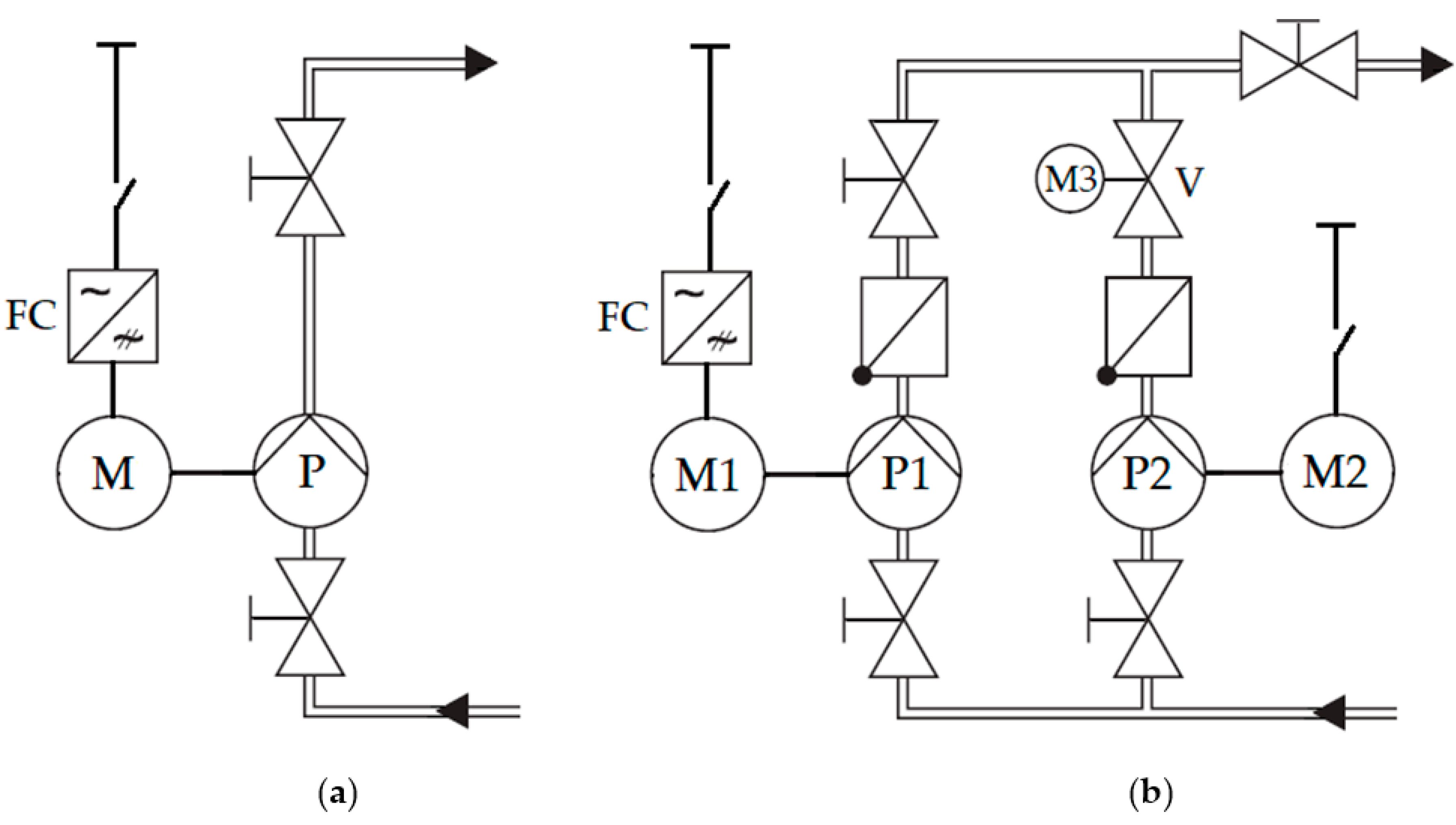
2. Structure of the Examined Pump Systems
- The pumping system with a single pump supplied with a VSD, the nominal power of 1500 W, and the nominal speed of 2900 rpm. Water supply is controlled by the speed control method;
- The multi-pump system with two parallel pumps, the nominal power of 750 W, and the nominal speed of 2900 rpm. The electric drive of the first pump is equipped with a VSD, and the second pump has an induction motor connected directly to a grid. The water supply is controlled by the VSD of the first pump and by throttling of the second pump.
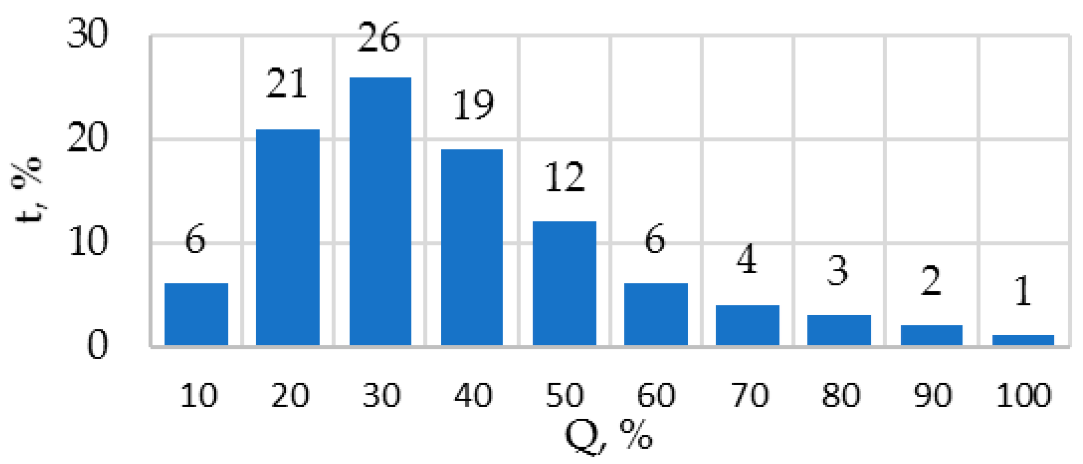
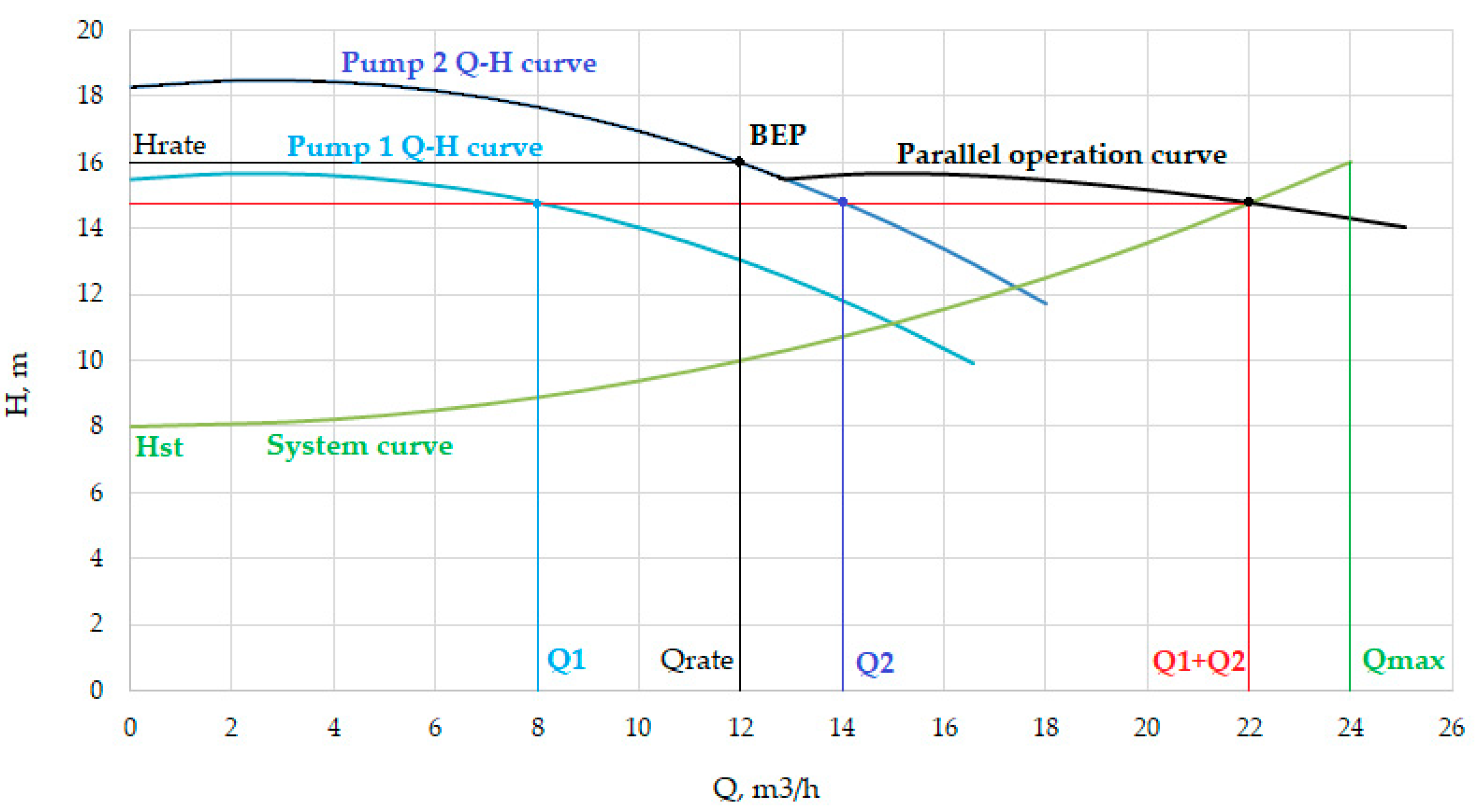
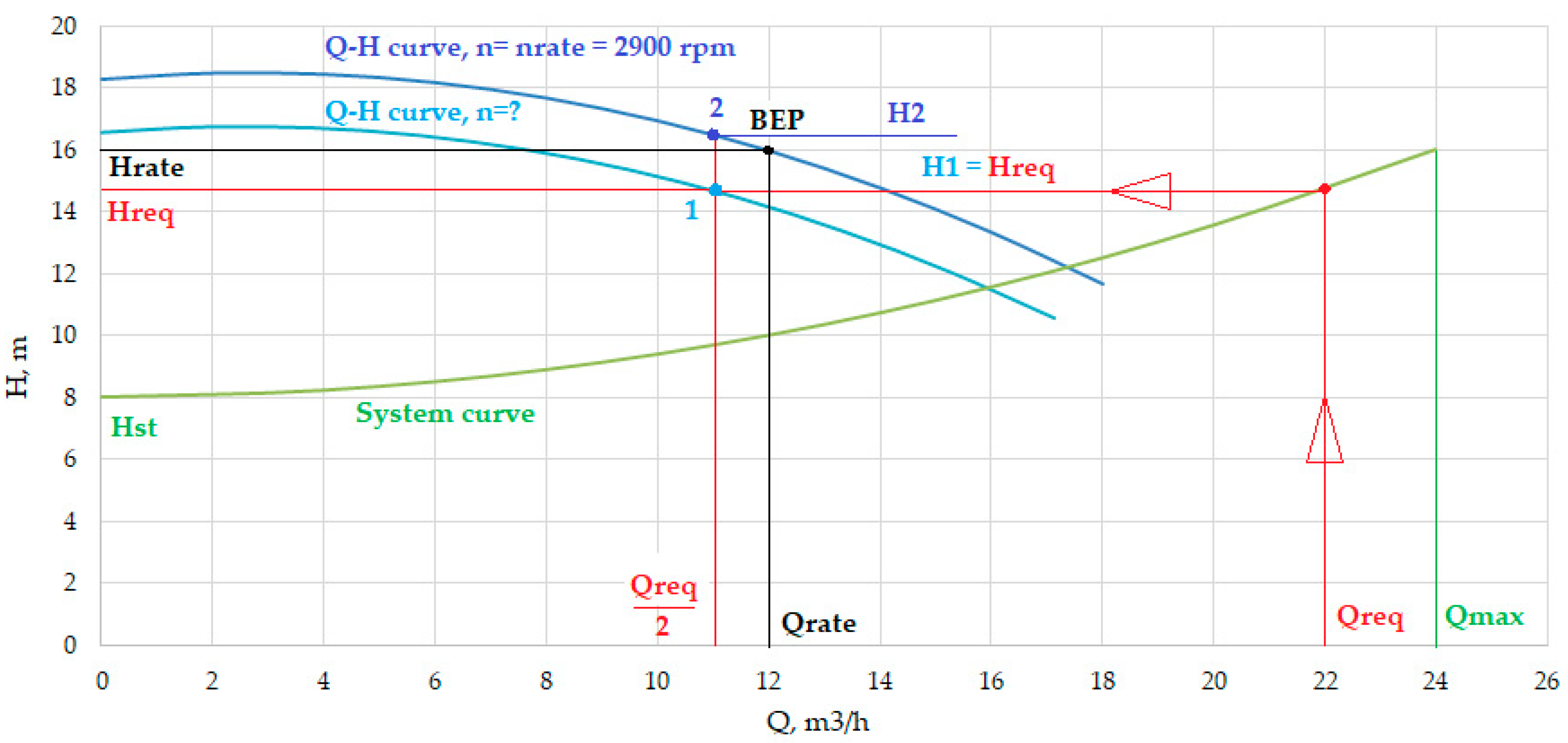
3. Operating Point Calculation for Pumps
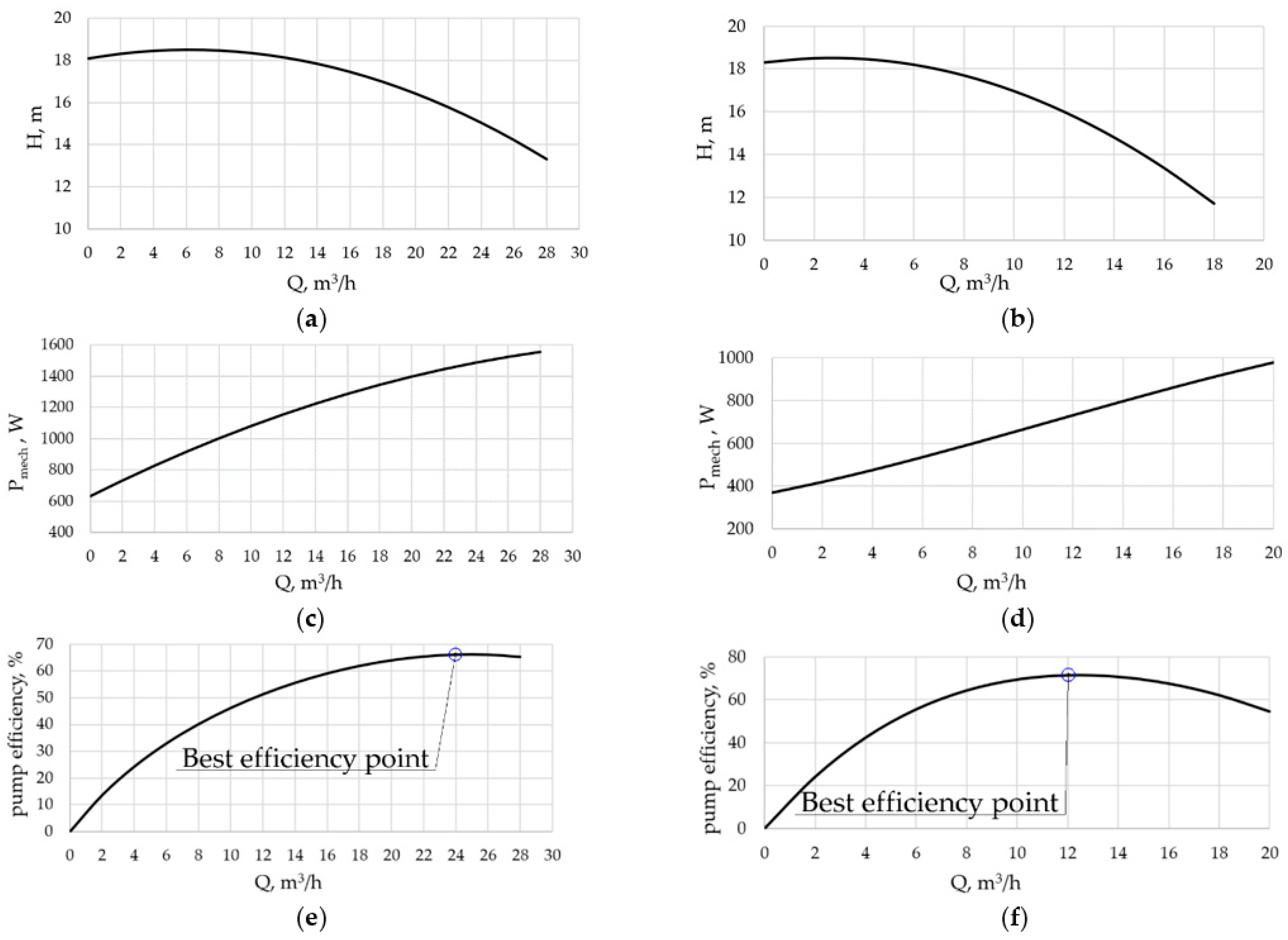
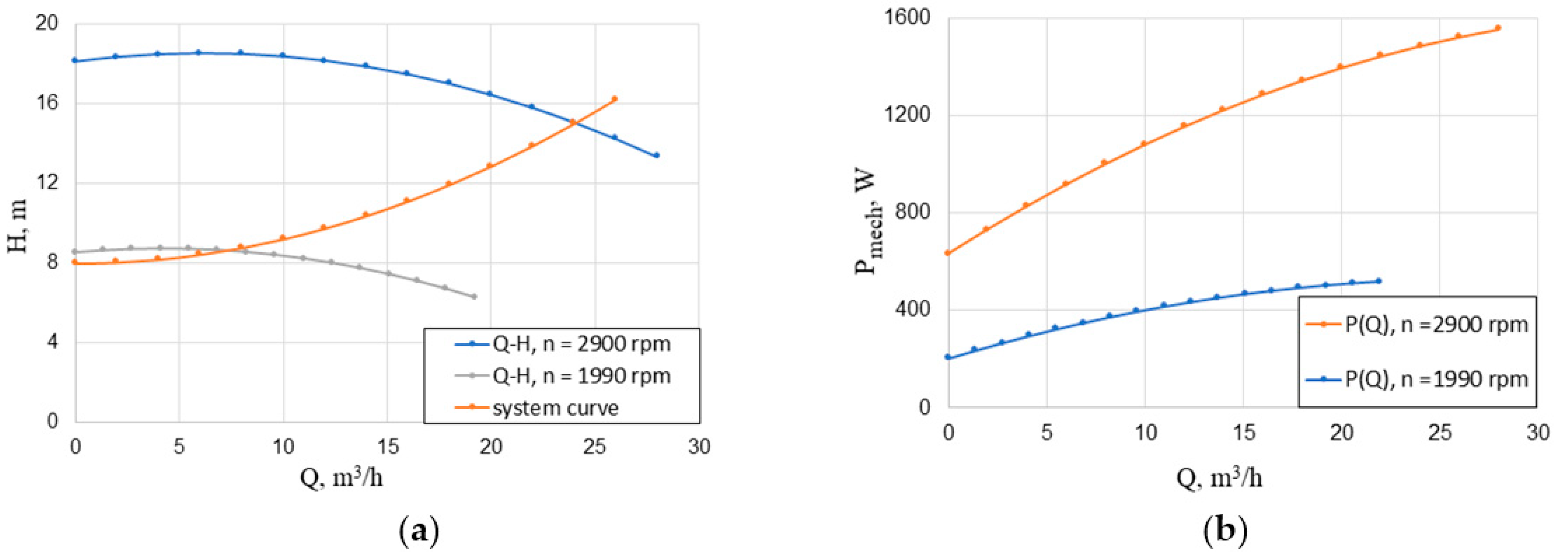
4. Determination of Pump Characteristics and Mechanical Power during the Operation Cycle
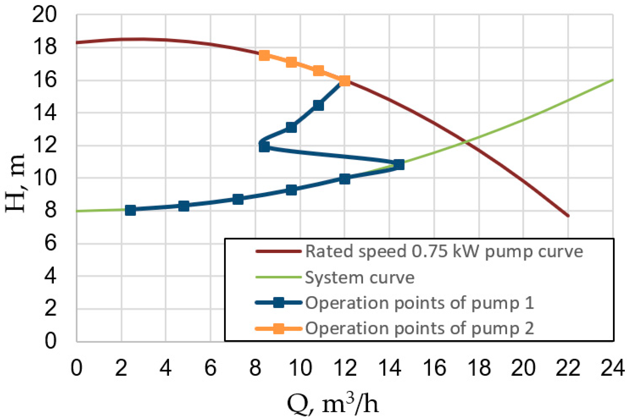
- Water flowrate regulation in the range from 0 to 60% is achieved by speed variation of the variable speed pump. A non-adjustable pump in this range of flows is not switched on and is closed by a return valve to prevent water from flowing through it in the backward direction;
- Water flowrate regulation in the range from 60 to 100% is achieved by the operation of both pumps. Water is supplied by joint control of the rotational speed of the 1st pump according to the regulation law (10) and of throttling the 2nd pump. In a dynamic mode, this type of regulation can be achieved with the help of proportional-integral (PI) controllers.
5. Assessment of Energy Consumption of the Two Considered Pump Systems
6. Conclusions
- The single-pump system is equipped with a single variable speed drive. The multi-pump system is equipped with one variable speed drive that is fed by a frequency converter and a non-adjustable drive connected directly to a grid;
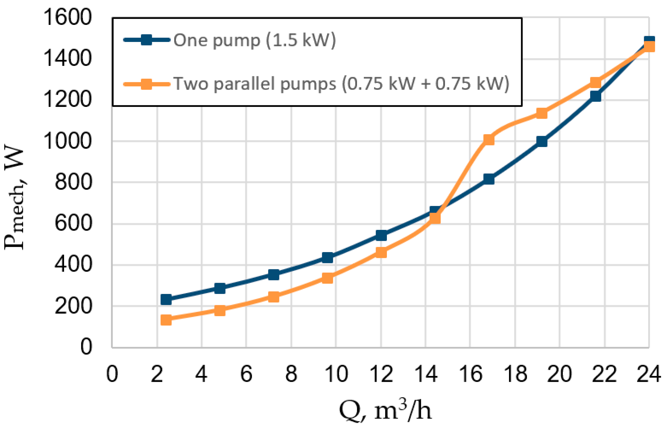
- The comparison of energy consumption for both pump system configurations shows that the usage of a multi-pump system supplied with two low-power pumps instead of a high-power pump in the single-pump system can lead to 29.8% energy savings;
- The energy savings are achieved due to the application of pumps and variable speed drives with a lower rated power and, therefore, with low losses in the operation modes in which the flowrate can be provided by one of the two pumps.
- Despite a rather low efficiency of the multi-pump system at high flowrates, the gain in the efficiency at the most frequent low flowrates results in an increase in the overall efficiency and energy saving.
- In future works, the optimization of the energy consumption of the considered configurations of multi-pump systems will be presented using mathematical optimization methods, considering the characteristics of motors and frequency converters.
Author Contributions
Funding
Acknowledgments
Conflicts of Interest
References
- European Commission. Study on Improving the Energy Efficiency of Pumps; Standards Publishing: London, UK, 2001. [Google Scholar]
- Nelik, L. Centrifugal and Rotary Pumps. Fundamentals with Applications; CRC Press: Boca Raton, FL, USA, 1999. [Google Scholar]
- Goman, V.; Oshurbekov, S.; Kazakbaev, V.; Prakht, V.; Dmitrievskii, V. Energy Efficiency Analysis of Fixed-Speed Pump Drives with Various Types of Motors. Appl. Sci. 2019, 9, 5295. [Google Scholar] [CrossRef]
- Kazakbaev, V.; Prakht, V.; Dmitrievskii, V.; Ibrahim, M.N.; Oshurbekov, S.; Sarapulov, S. Efficiency Analysis of Low Electric Power Drives Employing Induction and Synchronous Reluctance Motors in Pump Applications. Energies 2019, 12, 1144. [Google Scholar] [CrossRef]
- Shankar, V.K.A.; Umashankar, S.; Paramasivam, S.; Hanigovszki, N. A comprehensive review on energy efficiency enhancement initiatives in centrifugal pumping system. Appl. Energy 2016, 181, 495–513. [Google Scholar] [CrossRef]
- Viholainen, J. Energy-Efficient Control Strategies for Variable Speed Driven Parallel Pumping System Based on Pump Operation Point Monitoring with Frequency Converters. Ph.D Thesis, Lappeenranta University of Technology, Lappeenranta, Finland, 2014. [Google Scholar]
- Ahonen, T. Monitoring of Centrifugal Pump Operation by a Frequency Converter. Ph.D. Thesis, Lappeenranta University of Technology, Lappeenranta, Finland, 2011. [Google Scholar]
- Wu, P.; Lai, Z.; Wu, D.; Wang, L. Optimization Research of Parallel Pump System for Improving Energy Efficiency. J. Water Resour. Plan. Manag. 2015, 141, 04014094. [Google Scholar] [CrossRef]
- Viholainen, J.; Tamminen, J.; Ahonen, T.; Ahola, J.; Vakkilainen, E.; Soukka, R. Energy-efficient control strategy for variable speed-driven parallel pumping systems. Energy Effic. 2012, 6, 495–509. [Google Scholar] [CrossRef]
- Koor, M.; Vassiljev, A.; Koppel, T. Optimal Pump Count Prediction Algorithm for Identical Pumps Working in Parallel Mode. Procedia Eng. 2014, 70, 951–958. [Google Scholar] [CrossRef]
- Wen, Y.; Zhang, X.; Wang, P. The Relationship Between the Maximum Efficiency and the Flow of Centrifugal Pumps in Parallel Operation. J. Press. Vessel. Technol. 2010, 132, 034501. [Google Scholar] [CrossRef]
- Olszewski, P.; Arafeh, J. Parametric analysis of pumping station with parallel-configured centrifugal pumps towards self-learning applications. Appl. Energy 2018, 231, 1146–1158. [Google Scholar] [CrossRef]
- Olszewski, P. Genetic optimization and experimental verification of complex parallel pumping station with centrifugal pumps. Appl. Energy 2016, 178, 527–539. [Google Scholar] [CrossRef]
- Ahmed, A.; Moharam, B.; Rashad, E. Power Saving of Multi Pump-Motor Systems Using Variable Speed Drives. In Proceedings of the 2018 Twentieth International Middle East Power Systems Conference (MEPCON), Cairo, Egypt, 18–20 December 2018. [Google Scholar]
- Pandey, S.; Singh, R.P.; Mahar, P.S. Optimal Pipe Sizing and Operation of Multistage Centrifugal Pumps for Water Supply. J. Pipeline Syst. Eng. Pr. 2020, 11, 04020007. [Google Scholar] [CrossRef]
- Jia, M.; Zhang, J.; Xu, Y. Optimization Design of Industrial Water Supply Pump Station Considering the Influence of Atmospheric Temperature on Operation Cost. IEEE Access 2020, 8, 161702–161712. [Google Scholar] [CrossRef]
- Luo, Y.; Xiong, Z.; Sun, H.; Guo, Y. Research on energy-saving operation control model of the multi-type configuration centrifugal pump system with single invert. Adv. Mech. Eng. 2017, 9, 1–10. [Google Scholar] [CrossRef]
- Sike, H.; Xuejing, J.; Huifen, G. Optimization of the Number of Multiple Pumps Running Simultaneously in Open Cycle Cooling Water System in Power Plant. Energy Procedia 2012, 17, 1161–1168. [Google Scholar] [CrossRef]
- Jepsen, K.L.; Hansen, L.; Mai, C.; Yang, Z. Power consumption optimization for multiple parallel centrifugal pumps. In Proceedings of the 2017 IEEE Conference on Control Technology and Applications (CCTA), Mauna Lani, HI, USA, 27–30 August 2017. [Google Scholar]
- Saggewiss, G.; Kotwitz, R.; McIntosh, D. AFD synchronizing applications: Identifying potential methods and benefits. In Proceedings of the 2001 Petroleum and Chemical Industry Technical Conference (Cat. No.01CH37265), Toronto, ON, Canada, 26 September 2001; pp. 83–89. [Google Scholar] [CrossRef]
- Automation Pump, Pump Genius. Product Description, WEG. Document Code: 50059602, Revision 04, January 2019. Available online: https://static.weg.net/medias/downloadcenter/hb3/hda/WEG-pump-genius-50059602-brochure-en.pdf (accessed on 1 December 2020).
- Low Voltage AC Drives for Water, Wastewater & Irrigation Applications, FRENIC-AQUA, Product Description, Fuji Electric. Document Code: 24A1-E-0013, August 2012. Available online: https://www.fujielectric.com/products/ac_drives_lv/frenic-aqua/info/function.html (accessed on 1 December 2020).
- Stoffel, B. Assessing the Energy Efficiency of Pumps and Pump Units, 1st ed.; Elsevier: Darmstadt, Germany, 2015. [Google Scholar]
- Calpeda, N.M. Close Coupled Centrifugal Pumps with Flanged Connections, Catalogue; Calpeda S.p.A: Vicenza, Italy, 2018. [Google Scholar]
- Europump. Extended Product Approach for Pumps; Europump: Brussels, Belgium, 2014. [Google Scholar]
- Rotating Electrical Machines—Part 2-3: Specific Test Methods for Determining Losses and Efficiency of Converter-Fed AC Induction Motors; IEC 60034-2-3/Ed1; Standards Publishing: Geneva, Switzerland, 2013.
- The World’s Most Efficient Magnet-less Pump Motor; KSB SuPremE in IE5; KSB AG: Frankenthal, Germany, 2020.
- Low Voltage Process Performance Motors according to EU MEPS, Catalog, ABB, Document Code: 9AKK105944 EN 11-2014, October 2014. Available online: https://library.e.abb.com/public/23ff859eee0200c3c1257e1a002770a2/Catalog_Process_performance_acc_to_EU_MEPS_9AKK105944%20EN%2010_2014.low.pdf?filename=Catalog_Process_performance_acc_to_EU_MEPS_9AKK105944%20EN%2010_2014.low.pdf (accessed on 1 December 2020).
- Optidrive P2, AC Variable Speed Drive, 0.75 kW–250 kW / 1HP–350HP, 200–480 Volt 1 & 3 Phase; Advanced User Guide, Revision 1.00; Invertek Drives Ltd.: Buttington, UK, 2012; Available online: https://inverterdrive.com/file/Invertek-P2-Advanced-Guide (accessed on 1 December 2020).
- Safin, N.; Kazakbaev, V.; Prakht, V.; Dmitrievskii, V.; Sarapulov, S. Interpolation and analysis of the efficiency of a synchronous reluctance electric drive at various load points of a fan profile. In Proceedings of the 2018 25th International Workshop on Electric Drives: Optimization in Control of Electric Drives (IWED), Moscow, Russia, 31 January–2 February 2018. [Google Scholar]
- Eurostat Data. Eurostat Data for the Industrial Consumers in Germany; Eurostat: Eurostat—European Statistics; European Commission: Luxembourg, 2019. [Google Scholar]


| Qreq, % | 10 | 20 | 30 | 40 | 50 | 60 | 70 | 80 | 90 | 100 |
|---|---|---|---|---|---|---|---|---|---|---|
| n, rpm | 1918 | 1940 | 1991 | 2068.7 | 2181.4 | 2288 | 2424 | 2572 | 2731 | 2900 |
| Qreq, m3/h | 2.4 | 4.8 | 7.2 | 9.6 | 12 | 14.4 | 16.8 | 19.2 | 21.6 | 24 |
| H, m | 8.07 | 8.28 | 8.63 | 9.13 | 9.89 | 10.53 | 12.39 | 12.51 | 13.7 | 15 |
| Pmech, W | 234 | 290 | 356 | 437 | 547 | 663 | 817 | 1002 | 12,223 | 14,856 |
| Qreq, % | Qreq, m3/h | Q1, m3/h | Q2, m3/h | H1, m | H2, m | Pmech1, W | Pmech2, W | Pmech = Pmech1 + Pmech2, W | n1, rpm | n2, rpm |
|---|---|---|---|---|---|---|---|---|---|---|
| 10 | 2.4 | 2.4 | - | 8.1 | - | 136 | - | 136 | 1918 | - |
| 20 | 4.8 | 4.8 | - | 8.3 | - | 181 | - | 181 | 1975 | - |
| 30 | 7.2 | 7.2 | - | 8.7 | - | 247 | - | 247 | 2081 | - |
| 40 | 9.6 | 9.6 | - | 9.3 | - | 338 | - | 338 | 2229 | - |
| 50 | 12 | 12 | - | 10.0 | - | 463 | - | 463 | 2409 | - |
| 60 | 14.4 | 14.4 | - | 10.9 | - | 628 | - | 628 | 2615 | - |
| 70 | 16.8 | 8.4 | 8.4 | 11.9 | 17.6 | 394 | 616 | 1010 | 2433 | 2900 |
| 80 | 19.2 | 9.6 | 9.6 | 13.1 | 17.1 | 486 | 654 | 1140 | 2579 | 2900 |
| 90 | 21.6 | 10.8 | 10.8 | 14.5 | 16.6 | 598 | 691 | 1289 | 2736 | 2900 |
| 100 | 24 | 12 | 12 | 16.0 | 16.0 | 730 | 729 | 1460 | 2901 | 2900 |
| Operation Point | 1 | 2 | 3 | 4 | 5 | 6 | 7 |
|---|---|---|---|---|---|---|---|
| n, % | 90 | 50 | 90 | 50 | 25 | 50 | 25 |
| T, % | 100 | 100 | 50 | 50 | 100 | 25 | 25 |
| ηmotor IM-1.5 kW | 0.853 | 0.728 | 0.865 | 0.819 | 0.533 | 0.822 | 0.772 |
| ηmotor IM-750 W | 0.830 | 0.768 | 0.809 | 0.749 | 0.645 | 0.653 | 0.523 |
| ηconv. FC-1.5 kW | 0.965 | 0.947 | 0.952 | 0.925 | 0.905 | 0.888 | 0.784 |
| ηconv. FC-750 W | 0.937 | 0.906 | 0.898 | 0.849 | 0.857 | 0.771 | 0.686 |
| Qreq, % | 10 | 20 | 30 | 40 | 50 | 60 | 70 | 80 | 90 | 100 | |
|---|---|---|---|---|---|---|---|---|---|---|---|
| Qreq, m3/h | 2.40 | 4.80 | 7.20 | 9.60 | 12.0 | 14.4 | 16.8 | 19.2 | 21.6 | 24.0 | |
| System with one pump (FC-IM) | ηmotor | 0.431 | 0.507 | 0.580 | 0.651 | 0.723 | 0.783 | 0.838 | 0.874 | 0.879 | 0.834 |
| ηconv. | 0.939 | 0.944 | 0.950 | 0.955 | 0.960 | 0.963 | 0.964 | 0.961 | 0.957 | 0.952 | |
| Two parallel pumps (FC-IM1) + IM2 | ηmotor1 | 0.699 | 0.734 | 0.778 | 0.816 | 0.840 | 0.831 | 0.818 | 0.826 | 0.819 | 0.792 |
| ηmotor2 | - | - | - | - | - | - | 0.796 | 0.797 | 0.796 | 0.792 | |
| ηconv.1 | 0.431 | 0.507 | 0.580 | 0.651 | 0.723 | 0.783 | 0.838 | 0.874 | 0.879 | 0.834 | |
| Qreq, % | 10 | 20 | 30 | 40 | 50 | 60 | 70 | 80 | 90 | 100 | |
|---|---|---|---|---|---|---|---|---|---|---|---|
| Qreq, m3/h | 2.40 | 4.80 | 7.20 | 9.60 | 12.0 | 14.4 | 16.8 | 19.2 | 21.6 | 24.0 | |
| P1, W | Two parallel pumps | 213 | 272 | 347 | 453 | 599 | 812 | 1300 | 1465 | 1668 | 1928 |
| One pump | 580 | 605 | 646 | 704 | 788 | 880 | 1012 | 1192 | 1454 | 1872 | |
| Pump System | Eday, kWh | Eyear, kWh | Cyear, € | Syear, % | Syear, € |
|---|---|---|---|---|---|
| Two parallel pumps (FC-IM1) + IM2 | 12.37 | 4516 | 919 | 29.8 | 391.1 |
| System with one pump (FC-IM) | 17.63 | 6437 | 1310 | - | - |
Publisher’s Note: MDPI stays neutral with regard to jurisdictional claims in published maps and institutional affiliations. |
© 2020 by the authors. Licensee MDPI, Basel, Switzerland. This article is an open access article distributed under the terms and conditions of the Creative Commons Attribution (CC BY) license (http://creativecommons.org/licenses/by/4.0/).
Share and Cite
Oshurbekov, S.; Kazakbaev, V.; Prakht, V.; Dmitrievskii, V.; Gevorkov, L. Energy Consumption Comparison of a Single Variable-Speed Pump and a System of Two Pumps: Variable-Speed and Fixed-Speed. Appl. Sci. 2020, 10, 8820. https://doi.org/10.3390/app10248820
Oshurbekov S, Kazakbaev V, Prakht V, Dmitrievskii V, Gevorkov L. Energy Consumption Comparison of a Single Variable-Speed Pump and a System of Two Pumps: Variable-Speed and Fixed-Speed. Applied Sciences. 2020; 10(24):8820. https://doi.org/10.3390/app10248820
Chicago/Turabian StyleOshurbekov, Safarbek, Vadim Kazakbaev, Vladimir Prakht, Vladimir Dmitrievskii, and Levon Gevorkov. 2020. "Energy Consumption Comparison of a Single Variable-Speed Pump and a System of Two Pumps: Variable-Speed and Fixed-Speed" Applied Sciences 10, no. 24: 8820. https://doi.org/10.3390/app10248820
APA StyleOshurbekov, S., Kazakbaev, V., Prakht, V., Dmitrievskii, V., & Gevorkov, L. (2020). Energy Consumption Comparison of a Single Variable-Speed Pump and a System of Two Pumps: Variable-Speed and Fixed-Speed. Applied Sciences, 10(24), 8820. https://doi.org/10.3390/app10248820