Article

Failure Mechanism of Multilayer Ceramic Capacitors under Transient High Impact

ZNDY of Ministerial Key Laboratory, School of Mechanical Engineering, Nanjing University of Science and Technology, Nanjing 210094, China
*
Authors to whom correspondence should be addressed.
Appl. Sci. 2020, 10(23), 8435; https://doi.org/10.3390/app10238435
Submission received: 28 October 2020 / Revised: 24 November 2020 / Accepted: 25 November 2020 / Published: 26 November 2020
(This article belongs to the Special Issue Armour and Protection Systems)

Abstract

:
In recent years, penetrating weapons have been used more and more to attack increasingly hard targets; therefore, the impact of such a penetrating process has increased to an extremely high level. As an important component of a fuze, the reliability of the ceramic capacitor in high-impact environments is key for the normal working of the fuze. In this paper, we found that a high-impact causes parameter drift of the multilayer ceramic capacitor (MLCC), which further causes the fuze to misfire. This paper mainly studies the internal mechanism of the MLCC’s parameter drift during high impact. Firstly, transient physical phenomena, such as capacitance fluctuation and the leakage current increase of the ceramic capacitor under a high acceleration impact, were studied experimentally by a Machete hammer, revealing the relationship between the capacitance change, leakage current change, and acceleration under different working conditions. Secondly, a mechanical model of the ceramic capacitor is established to simulate the change in capacitance value, which shows that the main factor of the capacitance change is the deformation-derived change in the facing area between the electrodes. Lastly, an equivalent circuit model is established to simulate the change in the leakage current, which shows that the main factor of the leakage current change is the piezoelectric resistance of the ceramic dielectric.

Graphical Abstract

1. Introduction

A penetration weapon is a kind of high-value ammunition used for attacking strategic hard targets, such as weapon depots, missile launching sites, airport runways, and command centers. A penetration fuze is the “brain” of a penetrating weapon system, which precisely controls the burst point [1]. For the penetration fuze, a reliable power supply is the basis of its normal functioning. So, the multilayer ceramic capacitor (MLCC), which is the main energy-storage component of a penetration fuze, plays an important role in the reliability of the whole penetration weapon. Because the penetration fuze experiences an extreme impact, mechanical environment (acceleration up to hundreds of thousands of gravity g, lasting for a millisecond-wide pulse) [2,3], the reliability of the MLCC under high impact is very important.
Previous studies on the reliability of an MLCC under high-acceleration impact mostly focused on structural failure [4,5,6,7,8,9,10,11]. Prume et al. established a finite element simulation model for electrical, mechanical, and thermal coupling of an MLCC [12]; Lee et al. used a multi-scale homogenization modeling method to characterize the structural characteristics of multilayer ceramic capacitors [13]; Zhang et al. used the equivalent mechanical model to describe the impact-driven deformation of an MLCC and reveals that the electric field distortion resulting from the deformation can easily cause ceramic capacitor failure [14]; and He et al. discussed the failure of an MLCC through a high overload impact dynamic experiment and analyzed the influence of such a failure on the fuze system [15]. At present, the dynamic impact experiment and mechanical failure modeling are the most common ways to study the failure of an MLCC.
However, even there is no structural failure, it does not mean that no functional failure occurs in the MLCC and other electronic devices. Current research hotspots are focused on stress concentration and structural damage due to high impact. In actual working conditions, the MLCC did not have structural damage, but the penetration fuze still misfired due to the parameter drift. This paper focuses on the failure mechanism of an MLCC under high-impact conditions. In addition, it has been revealed that the tantalum capacitors and supercapacitors, two other kinds of energy-storage devices for a penetration fuze, still have capacitance parameter fluctuation without structural damage under a high-acceleration impact [16]. Gao et al. studied a fuze misfire caused by the sudden increase in leakage current of the tantalum capacitor under a high-g impact load [17]. Therefore, for an MLCC subjected to a strong impact, besides the structural failure, the functional failure problem of the parameter fluctuation is also important for practical application. However, the research in this area is still relatively scarce. In this paper, the changes in MLCC capacitance and leakage current upon subjection to a high impact are presented in real time, and the internal mechanism causing the electrical parameter changes is studied by physical field modeling and equivalent circuit modeling, which provides significant guiding towards the reliable use of an MLCC in a penetration fuze.

2. Experimental Study on MLCC Parameter Fluctuation Failure

2.1. Structure and Principle of an MLCC

A multilayer ceramic capacitor is mainly composed of an inner electrode, outer electrode, and ceramic dielectric material. A multilayer ceramic capacitor is composed of ceramic dielectric membranes printed with internal electrodes (mainly made of nickel, silver, palladium, and other metal materials) in a staggered manner. After one-time high-temperature sintering, the ceramic plates are formed, and the outer electrodes are sealed at both ends of the ceramic plates to form a monolith-like structure, as shown in Figure 1 [18,19].

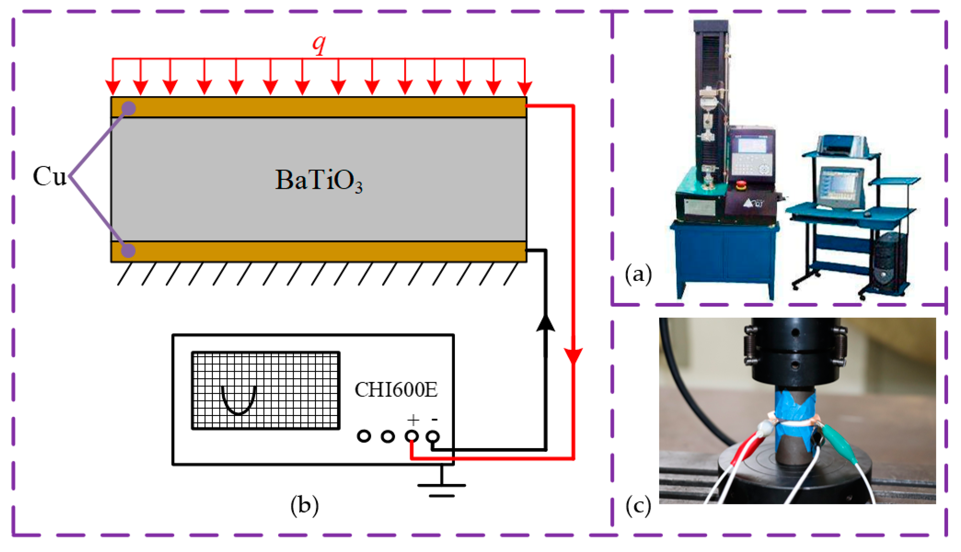
2.2. MLCC High-Impact Test System

An MLCC is often used as the main energy-storage element of a penetration fuze, which needs to withstand extreme environments, such as long pulse and high-g impact acceleration in the process of launching and penetrating. The impact can cause changes in the electrical parameters of the MLCC, among which the capacitance capacity and leakage current change are the most important to evaluate the capacitance failure. A Machete hammer is the most widely applied experimental system to research such extreme high-g impact environments, whose impact pulse width can reach hundreds of microseconds and impact value can reach up to tens of thousands of g. By adjusting the corresponding gear of a machete pawl, different acceleration values can be obtained upon releasing the pawl, which can simulate the actual mechanical environment of the fuze during the penetration process. The experimental system of the Machete hammer is shown in Figure 2.
Four kinds of ceramic capacitors with different capacities and different withstand voltages were used in the experiment. The capacitors were welded onto the Printed Circuit Board surface and fixed to the Machete hammer using thread. A piezoresistive high-g sensor (214-BM1009 type) was used to measure the acceleration signal during the impact process, with a sensitivity of 3.0 μV/g and a maximum range of 30,000 g. A Wayne Kerr 6500B series precision impedance analyzer was used to monitor the change in ceramic capacitance. An electrochemical workstation (CHI600E Series) was selected to monitor the change in leakage current. The ceramic capacitance parameters and test parameters are shown in Table 1. The subsequent modeling and simulation in this paper are based on these real device parameters.

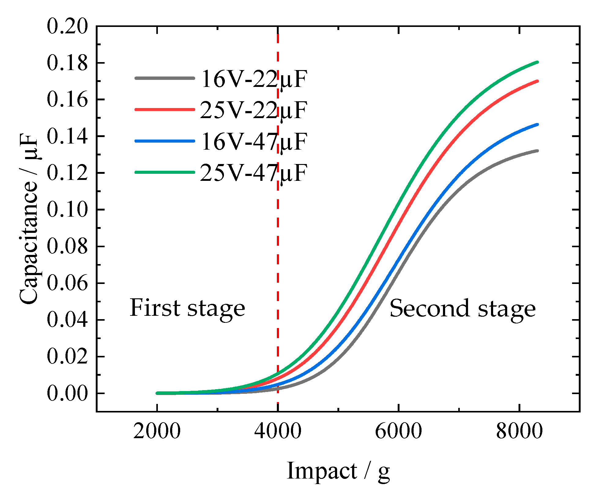
2.3. Transient Variation of Capacitance

The capacity of a ceramic capacitor changes during the impact process. Figure 3 shows that the capacity of the ceramic capacitor (type: 16V-22 μF) increased with increasing impact acceleration. Compared with the ceramic capacitors with different withstand voltages and differently rated capacities, when the peak value of impact acceleration exceeded 5000 g, the ceramic capacitance of them all have evident changes and the change value increased with the increasing impact peak value. The measured data of the changes are shown in Table 2. Among them, the capacitance value change reached 0.18 μF (absolute change); therefore, it cannot be ignored. In addition, the relationship between the MLCC capacitance change and impact acceleration is nonlinear, but the amount of change increases sharply after the threshold acceleration (>4000 g) is exceeded. This indicates that the higher acceleration the penetration fuze is subjected to, the more serious the reliability problem regarding capacity fluctuation can be. Besides, the larger the rated capacity and withstand voltage, the greater the capacitance fluctuation.
The experimental results show that, although the capacitance value changes at the moment of mechanical impact, it can restore to its original rated capacity after the impact, which verifies our view that even if the MLCC and other fuze devices do not have structural failure, various transient functional failures may still occur at the impact moment.

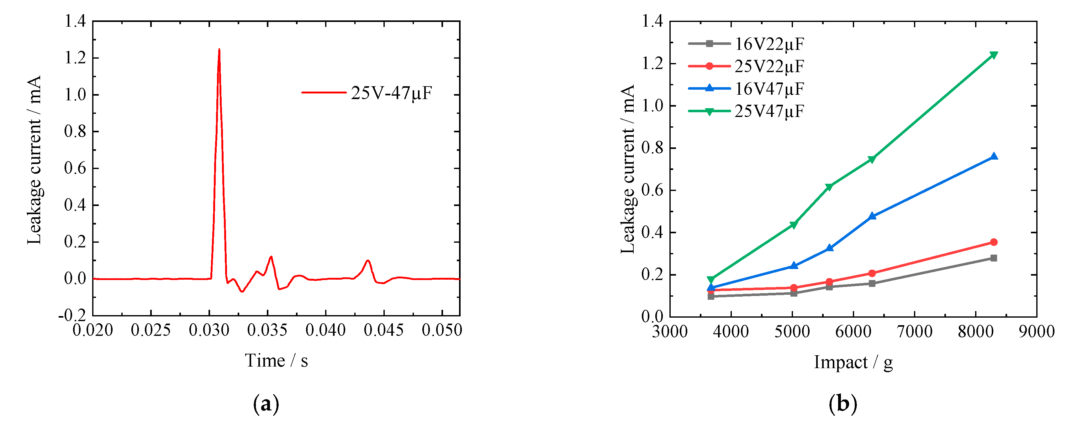
2.4. Transient Change of the Leakage Current

The leakage current of a multilayer ceramic capacitor is another key performance evaluation parameter. During the impact, the leakage current of the ceramic capacitor also changes significantly, causing ignored energy loss. According to Mattes et al. [20], the ceramic dielectric (BaTiO3) is not an absolutely ideal insulating material and has a piezoresistive effect. When the capacitor is charged, the electron penetrates through the dielectric layer and forms the leakage current. During the process of impact, the piezoresistive effect is evident, resulting in a sharp increase in the leakage current.
In this study, both ends of the MLCC are connected to the electrochemical workstation. Real-time monitoring of the leakage current changes by chronopotentiometry mode. Under such a mode, a constant voltage is applied between the two ends. When the impact acceleration is applied to the MLCC via the Machete hammer, the transient leakage current change is recorded by the electrochemical workstation. The change in leakage current of the ceramic capacitor is closely related to its structure. Figure 4 shows the leakage current of multilayer ceramic capacitors with different specifications changed under different impacts. In the process of the experiment, the peak value of the impulse acceleration increases gradually, and the leakage current of all types of capacitors increases suddenly, which is a universal phenomenon. Moreover, the change in leakage current can reach values of up to 1.2 mA (absolute change), so it cannot be ignored. In addition, the relationship between the leakage current change and impact acceleration rate is not linear; the amount of change increases sharply after the threshold (4000 g) is exceeded. This indicates that the higher the acceleration the penetration fuze is subjected to, the more serious the reliability problem of an increased leakage current can happen. Besides, the greater the rated capacity and withstand voltage, the greater the increase in leakage current. Note that the rated capacity has a greater influence than the withstand voltage on the leakage current fluctuation.

3. Modeling of MLCC Parameter Fluctuation Failure

The capacity of the MLCC increases with the increase in the impact peak value, which is due to the elastic deformation of the inner film-coated electrode of the MLCC during the impact, as shown in Figure 5. In the elastic range, the capacitance changes due to the change of the facing area between the electrodes.
Figure 6 shows a schematic diagram of the leakage current increase during impact. Under the mechanical pressure caused by the impact process, the electrical conductivity of the ceramic dielectric layer increases. So, the number of electrons passing through the dielectric layer increases, causing a larger leakage current.
Based on the above physical mechanism, in this paper, a dynamic mechanical model is established to analyze the influence of mechanical impact on capacity, and an equivalent circuit model is established to analyze the influence of mechanical impact on the leakage current.

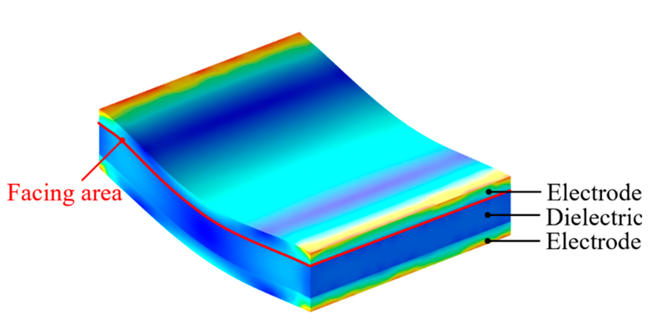
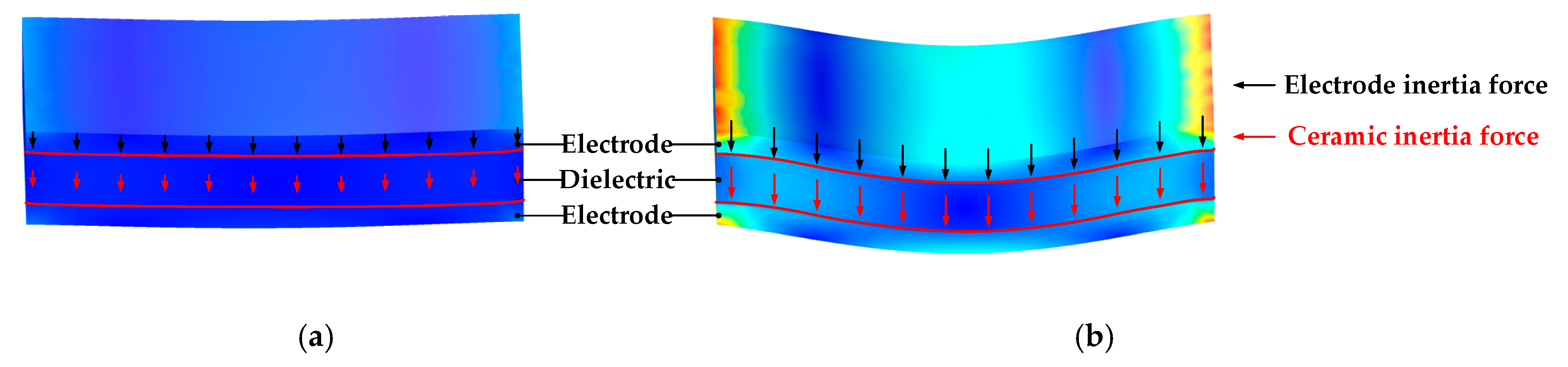
3.1. Modeling of Capacitance Fluctuation Based on Electrode Deformation

The basic unit of a multilayer ceramic capacitor is composed of two metal electrodes, which are separated by dielectric layer ceramics and stacked up in layers. The positive and negative charges are stored in the metal electrodes. Both ends of the electrode plate are coated in a ceramic dielectric. Therefore, the equivalent two-dimensional elastic mechanics problem of a ceramic capacitor electrode is shown in Figure 7. The coordinate system is length l along the X direction, width b along the Y direction, and thickness h along the Z direction. When the plate is subjected to the inertial force F, the upper surface is compressed and the lower surface is stretched. The bending moment M produced by any single element under the inertial force is m, and the number of electrode layers is N.
Under the impact acceleration a , the uniformly distributed load q is as follows:
q = F N l = m a N l = b h ρ a N
The deflection function of the electrode under the uniform load q is as follows [21]:
w ( x ) = m a 24 N E I l x 2 ( l x ) 2 = ρ a 2 N E h 2 x 2 ( l x ) 2
where the cross-sectional area of the inner electrode is given by A = b·h, the material density is ρ , and the elastic modulus of the material is E.
When x = l / 2 , the maximum deflection of the plate is as follows:
w max = ρ l 4 a 32 N E h 2
The rotation function θ ( x ) of the inner electrode is as follows:
θ ( x ) = w ( x ) '
By deriving x, we obtain the following results:
θ ( x ) = ρ a N E h 2 x ( l 2 x ) ( l x )
Then, the length l of the electrode after impact is bent to the arc length l’:
l = 0 l 1 + [ ρ a N E h 2 x ( l 2 x ) ( l x ) ] 2 d x
Then, the arc length change l is as follows:
l = l l = 0 l 1 + [ ρ a N E h 2 x ( l 2 x ) ( l x ) ] 2 d x l
The surface area change S of the inner electrode is obtained as follows:
S = l · b = { 0 l 1 + [ ρ a N E h 2 x ( l 2 x ) ( l x ) ] 2 d x l } · b
The capacity of the inner electrode unit of the ceramic capacitor is as follows:
C N 2 = ε S 2 N π k d
Therefore, the capacitance change C is as follows:
C = N 2 · ε S 2 N π k d = ε 4 π k d · l · b = { 0 l 1 + [ ρ a N E h 2 x ( l 2 x ) ( l x ) ] 2 d x l } · b
According to the numerical calculation of the above mechanical model, the results are shown in Figure 8. The relationship between the capacity change and the impact acceleration presents two stages: first, it changes gently, then rises rapidly. Further, as shown in Figure 9, the first stage has a slow capacity change because the electrode and ceramic dielectric are closely connected when the impact acceleration is lower than the deformation threshold of the ceramic dielectric and the deflection deformation is small, and the facing area of the inner electrode changes only a little; therefore, the capacity change is not obvious. In the second stage, the impact acceleration exceeds the threshold, the deflection of the electrode is obvious, the facing area of the inner electrode increases, and the capacity and impact acceleration almost increase with a linear relation. The comparison between Table 2 and Table 3 shows that the main conclusions of both the simulation and experiment are the same, indicating that the mechanical model proposed above is credible. Specifically, the quantitative value of the absolute capacity change of the simulation is slightly lower than that of the experiment. The reason for this is that the simulation does not consider the mechanical two-dimensional equivalent model and simplifies the influence of the transverse strain. The variation in the electrode thickness direction is not an ideal factor, which leads to the deviation between the simulation results and the experimental results.

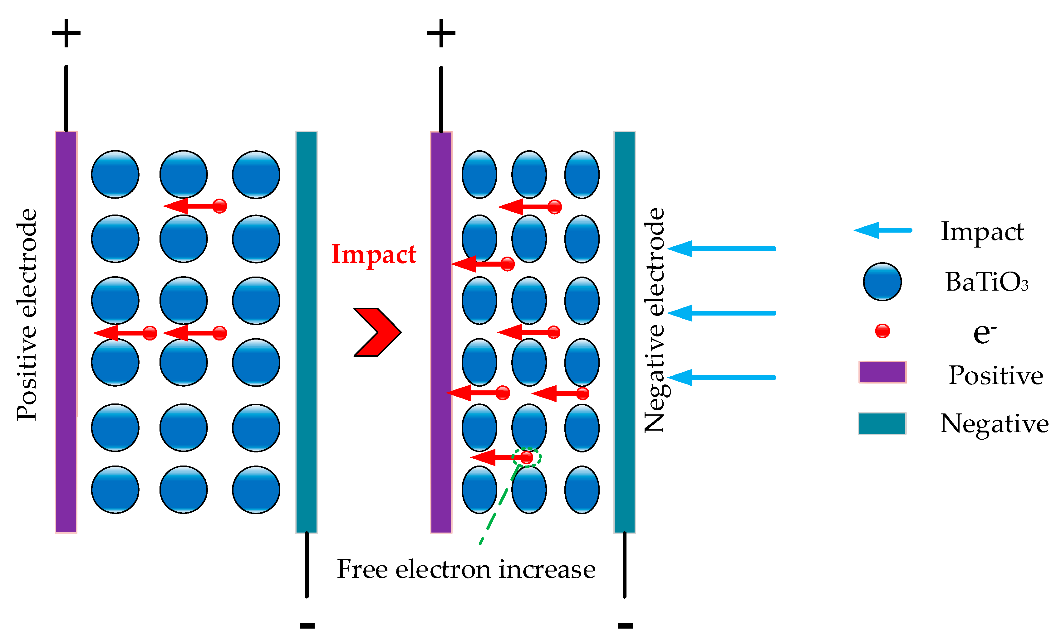
3.2. Modeling of Leakage Current Fluctuation Based on the Piezoresistive Effect

In this study, the leakage current of the ceramic capacitor returned to its original state after the impact. According to the theoretical model of the equivalent circuit, the main factor affecting the leakage current is the ceramic dielectric insulation resistance [22]. Therefore, the key to solving the leakage current is to study the relationship between the pressure and ceramic dielectric insulation resistance.

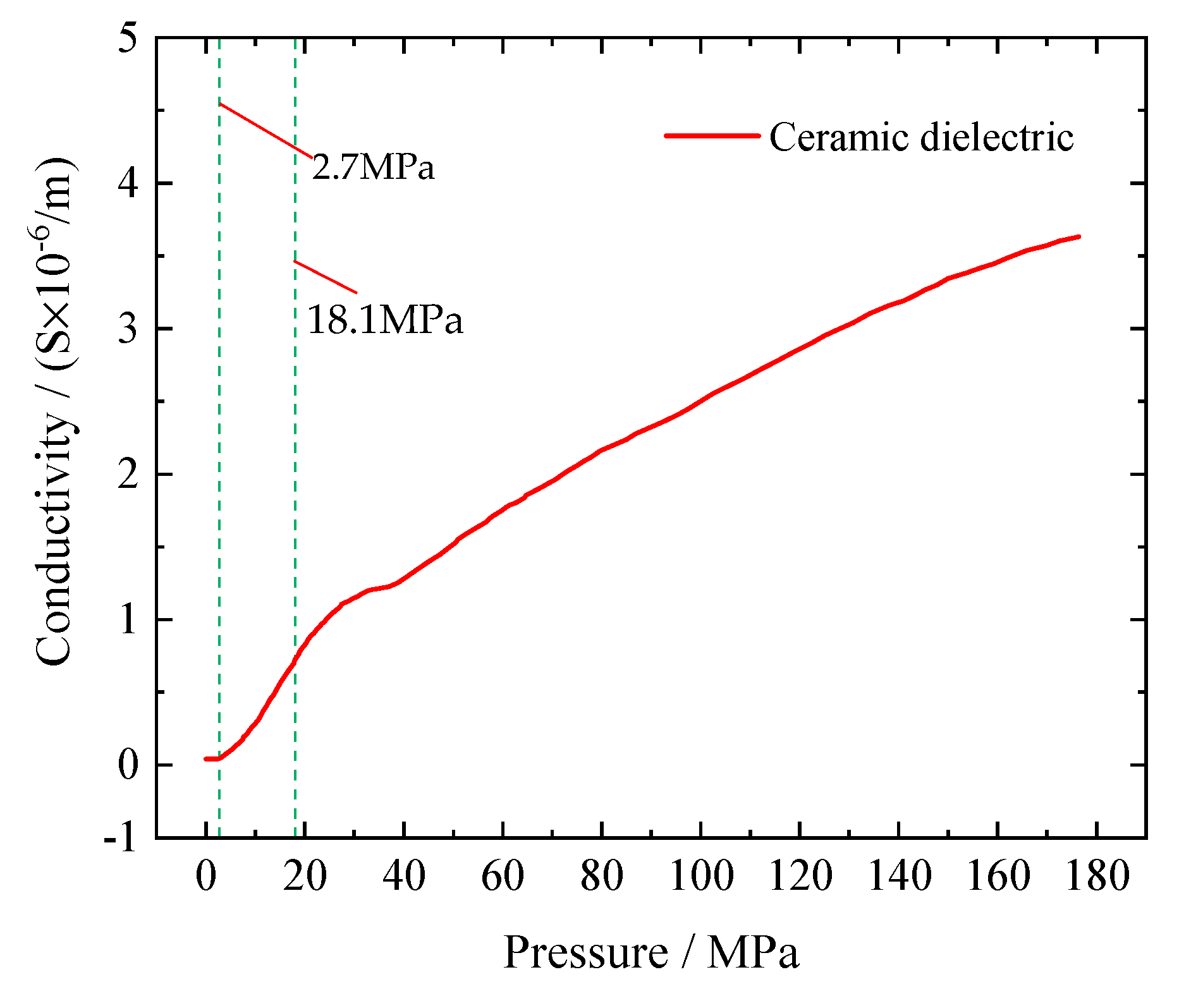
3.2.1. Piezoresistive Model of Ceramics

As shown in Figure 10, a static load is applied to the ceramic dielectric and the constant voltage (10V) of the electrochemical workstation (CHI600E Series) is used to monitor the real-time current change in order to obtain the resistance values of the ceramics under different pressures. The static pressure test showed that, with the increase in pressure, the insulation impedance of the ceramic dielectric decreased. In Figure 11 we see that the resistance of the ceramic dielectric began to decrease when the threshold pressure was 2.7 MPa, and the resistance dropped gradually when the pressure reached 18.1 MPa. In Figure 12, the relationship between ceramic conductivity and pressure is shown.
According to Newton’s second law, the relationship between acceleration and pressure is as follows:
p ( t ) = m a ( t ) / A
where m—mass; A—cross-sectional area.
According to the experimental results, the relationship between pressure P and resistance R (P–R equation) is as follows:
R ( p ) = { 256 , p 2.34 ; R 0 + A 1 · ( 1 e ( ( p T 1 ) / M 1 ) ) + A 2 · ( 1 e ( ( p T 2 ) / M 2 ) ) , p > 2.34 ;
The parameters in the P-R equation are shown in Table 4.

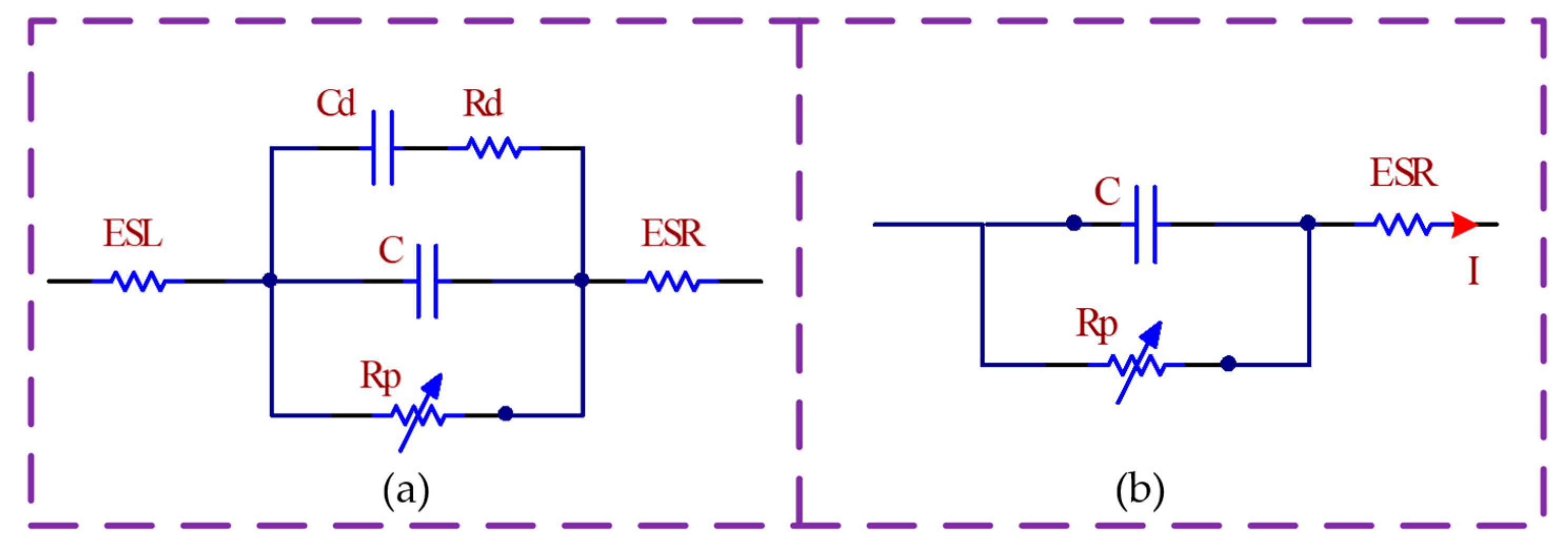
3.2.2. Theoretical Model of Equivalent Circuit for Multilayer Ceramic Capacitor

The characteristics of an MLCC are not ideal due to the parasitic effects. Many scholars use the following equivalent circuit model to describe the capacitance [23], as shown in Figure 13a. This paper focuses on the influence of the mechanical impact on the MLCC (mainly determined by the ceramic dielectric resistance, Rp), which is not significantly related to the parasitic effects. So, the equivalent circuit model is simplified as Figure 13b:
Where C is MLCC capacity, Ck is the storage capacity of one pair of positive and negative electrodes, ESR(Rs) is the equivalent series resistance, and Rp is the equivalent resistance of the ceramic dielectric:
According to the equivalent circuit, the mathematical model can be established as follows:
I l , 0 R s + V p , 0 = U 0
( C k V p , k Δ t + V p , k R p , k ) R s = U 0 V p , k
V p , k = U 0 C k R s e 1 C k k = 1 n ( 1 R p , k + 1 R s ) t [ e 1 C k k = 1 n ( 1 R p , k + 1 R s ) Δ t d t ]
I l , k = U 0 V p , k R s
where U0 is the constant voltage applied to the MLCC, Vp,k are the voltages of the ceramic dielectric between the kth pair of positive and negative electrodes, and the conductivity of Rp varies with the impact.
After combining the equivalent circuit model (Equations (13)–(16)) and the P–R model (Equations (11) and (12)), perform the process calculation in Figure 14 to obtain the relationship between acceleration and leakage current:
The piezoresistive effect of the ceramic dielectric is the main factor that causes the change in leakage current. The impact acceleration has the characteristics of a pulse signal. Therefore, the corresponding impact stress waves at different moments of the impact have different pressures on the ceramic dielectric, which in turn causes pulsed changes in the leakage current.
According to the static pressure data model of the ceramic dielectric and the mathematical model of an equivalent circuit, the relationship between the conductivity of the ceramic dielectric and the leakage current is presented, as shown in Figure 15. As the conductivity increases, the leakage current increases.
In addition, the leakage current variation of a multilayer ceramic capacitor under different impacts is simulated, as shown in Figure 16.
The results show that the leakage current increases approximately exponentially with the increasing impact acceleration, which is in good agreement with the experimental results (Figure 4). The sudden increase in leakage current of the ceramic capacitors causes the loss of energy storage, which makes the detonator energy insufficient. Therefore, the design of the fuze’s energy-storage capacitor must consider the leakage current during the impact and increase the design margin to ensure the reliability of the fuze effect.

4. Conclusions

In this paper, the transient change (and its mechanism) of the electronical parameters of multilayer ceramic capacitors during high-g impacts was analyzed via Machete hammer experiments. Further, by establishing a mechanical model and equivalent circuit model, the capacity and leakage current changes were studied, and a numerical simulation was carried out to verify the experimental results. To sum up, the experimental and simulation results indicate the following issues:
(1)
Under high-g impact acceleration, in the MLCC occurs the phenomenon of parameter drift, in which the capacitance value becomes larger and the leakage current increases. Besides, the larger the rated capacitance and withstand voltage of the MLCC, the greater the capacitance change and leakage current drift. With impact acceleration of no more than 9000 g, the influence on the capacity and leakage current are reversible.
(2)
The facing area deformation is the dominant factor in the transient change of the capacity value. A mechanical model based on the facing area is established to calculate the capacity change. The numerical calculation results are consistent with the experimental results, and the relationship between the impact and capacity changes can be described semi-quantitatively.
(3)
The piezoresistive effect of the ceramic dielectric is the dominant factor in leakage current variation. The insulation resistance begins to decrease when the threshold pressure exceeds 2.7 MPa. With increasing pressure, the insulation impedance of the ceramic dielectric decreases continuously, and when the pressure reaches 18.1 MPa, the resistance drops gradually. By combining the P-R model and the equivalent circuit model, the relationship between the leakage current and impact acceleration can be simulated, which is an approximately exponentially increasing relationship.
(4)
The sudden increase in the leakage current of the ceramic capacitor causes the energy storage loss of the MLCC, which makes the detonator energy of the fuze insufficient. The design of the fuze’s energy-storage capacitor must consider the leakage current during the impact and increase the design margin to ensure the reliability of the fuze.
By analyzing the relationship between the different impact accelerations and parameter drift, and by calculating the failure threshold of the different specification parameters of the MLCC according to the mechanical model and equivalent circuit model, effectively provides guidance for the design of a penetration fuze’s MLCC, to ensure the reliability of the fuze.

Author Contributions

D.Y. and K.D. conceived and designed the experiments; D.Y., J.Z. and B.Y. performed the experiments; D.Y. and K.D. analyzed the data; H.Z. and S.M. contributed analysis tools; D.Y. wrote the paper. All authors have read and agreed to the published version of the manuscript.

Funding

This research was funded in part by Key Basic Research Projects of Basic Strengthening Plan of China (Grant number 2017-JCJQ-ZD-004), in part by National Natural Science Foundation of China (Grant number 52007084), in part by the Natural Science Foundation of Jiangsu Province under Grant (BK20190470), and in part by the Central University Special Funding for Basic Scientific Research (Grant number 30918012201).

Conflicts of Interest

The authors declare no conflict of interest.

References

  1. He, Z. Basic Theory and Application of Smart Fuze Design, 2nd ed.; Beijing Institute of Technology Press: Beijing, China, 2019; pp. 183–237. [Google Scholar]
  2. He, Z. Fuze and environment. J. Detect. Control 2019, 41, 1–5. [Google Scholar]
  3. Zhang, H.; Dai, K.; Yin, Q. Ammunition Reliability Against the Harsh Environments During the Launch of an Electromagnetic Gun: A Review. IEEE Access 2019, 7, 45322–45339. [Google Scholar] [CrossRef]
  4. Dai, K.; Wang, X.; Niu, S.; Yi, F.; Yin, Y.; Chen, L.; Zhang, Y.; You, Z. Simulation and structure optimization of triboelectric nanogenerators considering the effects of parasitic capacitance. Nano Res. 2016, 10, 157–171. [Google Scholar] [CrossRef]
  5. Archangelo, K.; Guilardi, L.; Campanelli, D.; Valandro, L.F.; Borges, A. Fatigue failure load and finite element analysis of multilayer ceramic restorations. Dent. Mater. 2019, 35, 64–73. [Google Scholar] [CrossRef] [PubMed]
  6. Nagayoshi, M.; Matsubara, K.; Fujikawa, N. Analyses of microstructure at degraded local area in Ni-multilayer ceramic capacitors under highly accelerated life test. Jpn. J. Appl. Phys. 2020, 59, SPPC01. [Google Scholar] [CrossRef]
  7. Kalaiselvan, C.; Rao, L.B. Accelerated life testing of nano ceramic capacitors and capacitor test boards using non-parametric method. Measurement 2016, 88, 58–65. [Google Scholar] [CrossRef]
  8. Lall, P.; Dornala, K.; Suhling, J. Effect of Dielectric Material on the Reliability of 3640 MLCC Capacitors under High-G Shock Loads. In Proceedings of the 2019 18th IEEE Intersociety Conference on Thermal and Thermomechanical Phenomena in Electronic Systems, Las Vegas, NV, USA, 28–31 May 2019; pp. 1037–1046. [Google Scholar]
  9. Lall, P.; Dornala, K.; Deep, J. Measurement and Prediction of Interface Crack Growth at the PCB-Epoxy Interfaces Under High-G Mechanical Shock. In Proceedings of the 2018 17th IEEE Intersociety Conference on Thermal and Thermomechanical Phenomena in Electronic Systems, San Diego, CA, USA, 29 May–1 June 2018; pp. 1097–1105. [Google Scholar]
  10. Lall, P.; Dornala, K.; Lowe, R. Survivability Assessment of Electronics Subjected to Mechanical Shock Up to 25,000g. In Proceedings of the 2016 15th IEEE Intersociety Conference on Thermal and Thermomechanical Phenomena in Electronic Systems, Las Vegas, NV, USA, 31 May–3 June 2016; pp. 507–518. [Google Scholar]
  11. Lall, P.; Patel, K.; Lowe, R. Modeling and reliability characterization of area-array electronics subjected to high-g mechanical shock up to 50,000 g. In Proceedings of the 2012 IEEE 62nd Electronic Components and Technology Conference, San Diego, CA, USA, 29 May–1 June 2012; pp. 1194–1204. [Google Scholar]
  12. Klaus, P.; Rainer, W.; Klaus, F. Finite-Element Analysis of Ceramic Multilayer Capacitors: Modeling and Electrical Impedance Spectroscopy for a Nondestructive Failure Test. J. Am. Ceram. Soc. 2000, 83, 1153–1159. [Google Scholar]
  13. Pyo, L.S.; Weon, K.K. Analysis for deformation behavior of multilayer ceramic capacitor based on multiscale homogenization approach. J. Mech. Sci. Technol. 2018, 32, 2577–2585. [Google Scholar]
  14. Xuhui, Z.; Kuahai, Y.; Hongyu, X.; Bin, L.; Xingguo, K. Failure analysis of multilayer ceramic capacitor structure under high G impact load. Electron. Compon. Mater. 2016, 35, 28–31. [Google Scholar]
  15. Ronghua, H.; Ya, Z.; Bo, L.; Yunluan, H.; Pan, G. Parameter variation and failure analysis of military capacitance under high overload. Reliab. Environ. Test Electron. Prod. 2010, 28, 24–26. [Google Scholar]
  16. Keren, D.; Xiaofeng, W.; Yin, Y.; Hao, C.; Zheng, Y. Voltage Fluctuation in a Supercapacitor during a High-g Impact. Sci. Rep. 2016, 6, 38794. [Google Scholar]
  17. Changlong, L.; Shiqiao, G.; Shaohua, N.; Haipeng, L. Parameter variation of solid tantalum capacitor under high shock. Explos. Shock 2018, 38, 419–425. [Google Scholar]
  18. Kim, J.H.; Jeong, H.C. Ceramic Electronic Component and Method of Manufacturing the Same. 2013. Available online: https://www.freepatentsonline.com/y2013/0049532.html (accessed on 26 November 2020).
  19. Chazono, H. Structure-Property Relationship in Ni-MLCC: Composition & Microstructure. IEICE Tech. Rep. Compon. Parts Mater. 2002, 102, 7–12. [Google Scholar]
  20. Mattes, B.L. Secondary Piezoresistivity in Oxygen Deficient BaTiO3 Single Crystals. J. Appl. Phys. 1963, 34, 682–685. [Google Scholar] [CrossRef]
  21. Guojun, S. Material Mechanics; Shanghai Jiaotong University Press: Shanghai, China, 2006; pp. 220–323. [Google Scholar]
  22. Hong, K.; Lee, T.H.; Suh, J.M. Perspectives and challenges in multilayer ceramic capacitors for next generation electronics. J. Mater. Chem. C 2019, 7, 9782–9802. [Google Scholar] [CrossRef]
  23. Kim, M.G. Equivalent-Circuit Model for High-Capacitance MLCC Based on Transmission-Line Theory. IEEE Trans. Compon. Packag. Manuf. Technol. 2012, 2, 1012–1020. [Google Scholar] [CrossRef]
Figure 1. Application of a multilayer ceramic capacitor (MLCC) in a penetration weapon. (a) The penetration process in a military application. (b) The MLCC is the energy-storage element of a penetration fuze. (c) Internal structure diagram of the MLCC.
Applsci 10 08435 g001
Figure 2. Experimental system diagram: (a) schematic diagram of a Machete hammer test system; (b) installation diagram of the capacitance and sensor.
Applsci 10 08435 g002
Figure 3. Change in ceramic capacitance with impact acceleration. (a) The impact peak value is 5209 g. (b) The impact peak value is 5608 g. (c) The impact peak value is 6305 g. (d) The impact peak value is 8297 g.
Applsci 10 08435 g003
Figure 4. Relationship between the leakage current and impact in multilayer ceramic capacitors: (a) leakage current of an MLCC (25V47µF) under 8297 g impulse; (b) leakage current variation of multilayer ceramic capacitors with different impacts.
Applsci 10 08435 g004
Figure 5. Diagram of the facing area increase during impact.
Applsci 10 08435 g005
Figure 6. Schematic diagram of the leakage current increase during impact.
Applsci 10 08435 g006
Figure 7. Equivalent diagram of the inner electrode: (a) schematic diagram of the electrode; (b) schematic diagram of electrode equivalent mechanical model.
Applsci 10 08435 g007
Figure 8. Relationship between capacity change and impact acceleration.
Applsci 10 08435 g008
Figure 9. Deformation of the MLCC at different stages: (a) the first stage; (b) the second stage.
Applsci 10 08435 g009
Figure 10. System diagram of the ceramic static pressure test: (a) hydrostatic machine; (b) ceramic static pressure diagram; (c) ceramic static pressure experiment.
Applsci 10 08435 g010
Figure 11. Relationship between pressure and ceramic conductivity: (a) the change of ceramic current in static pressure experiment; (b) the relationship between ceramic dielectric pressure and resistance.
Applsci 10 08435 g011
Figure 12. Relationship between pressure and ceramic resistance.
Applsci 10 08435 g012
Figure 13. MLCC equivalent circuit model: (a) general equivalent circuit model of the MLCC; (b) simplified equivalent circuit model of the MLCC.
Applsci 10 08435 g013
Figure 14. Flow chart of the leakage current calculation.
Applsci 10 08435 g014
Figure 15. Relationship between leakage current and ceramic conductivity.
Applsci 10 08435 g015
Figure 16. Relationship between leakage current and impact acceleration of the MLCC.
Applsci 10 08435 g016
Table 1. Capacitance specifications and measurement parameters.
Capacitor Typeδ (µm)Nh (µm)l (µm)b (µm)S (mm2)
“J”CT41G-1210-X5R-16V-22µF3.115011.31294520595.34
“J”CT41G-1210-X5R-25V-22µF2.913791.81316521615.99
“J”CT41G-1210-X5R-16V-47µF1.794621.96323821846.22
“J”CT41G-1210-X5R-25V-47µF2.575701.76336423697.05
Where δ—thickness of dielectric layer; N—number of electrode layers; h—thickness of electrode layer; l—electrode length; b—electrode width; and S—effective facing area.
Table 2. Capacity change of the MLCC under a different impact acceleration.
Capacitor TypeCapacitance Variation/µF
5026 g5608 g6305 g8297 g
“J”CT41G-1210-X5R-16V-22µF0.0220.0300.1060.146
“J”CT41G-1210-X5R-25V-22µF0.0270.0330.1090.151
“J”CT41G-1210-X5R-16V-47µF0.0310.0560.1220.174
“J”CT41G-1210-X5R-25V-47µF0.0370.0600.1270.181
Table 3. Simulation capacity change of the MLCC under different impacts.
Capacitor ModelCapacitance Variation/µF
5026 g5608 g6305 g8297 g
“J”CT41G-1210-X5R-16V-22µF0.0110.0280.0820.129
“J”CT41G-1210-X5R-25V-22µF0.0170.0330.0910.141
“J”CT41G-1210-X5R-16V-47µF0.0290.0540.1120.164
“J”CT41G-1210-X5R-25V-47µF0.0380.0590.1230.175
Table 4. P–R model parameters.
R0A1T1M1A2T2M2
457 MΩ−248−18.911.9−2042.342.33
Publisher’s Note: MDPI stays neutral with regard to jurisdictional claims in published maps and institutional affiliations.

