Article

Double-Probe Ultrasonic Detection Method for Cracks in Steel Structure

College of Civil and Transportation Engineering, Hohai University, Nanjing 210098, China
*
Author to whom correspondence should be addressed.
Appl. Sci. 2020, 10(23), 8436; https://doi.org/10.3390/app10238436
Submission received: 27 October 2020 / Revised: 24 November 2020 / Accepted: 25 November 2020 / Published: 26 November 2020

Abstract

:
To investigate the feasibility analysis of ultrasonic detection methods applied in the fatigue crack characteristics of steel structures, the double-probe ultrasonic detection method was applied to the prefabricated crack specimens fabricated from of flat steel plate. The test features including length, width, depth, angle, and crack location were considered. Based on the calculation of geometric relationship and experimental results, a method for judging the crack tip position was developed. The formulae for determining the depth and angle of crack were not only established but also analyzed the detection accuracy of the double-probe penetration method. The feasibility of this method in weld crack detection was verified by a combination of the finite-element simulation and actual experiment. The results showed that the ratio of crack tip wave height to crack free wave height ωK is related to the K value (K value is one of the parameters of the angle probe, which is defined as the tangent value of angle β between the incident wave and an interface normal line), but the influence of crack depth and width can be ignored. Due to higher detection accuracy for crack depth and angle, a double-probe penetrating method could improve the detection accuracy for crack angle by nearly 5% more than the single probe pulse reflection method. Therefore, application of the double-probe penetrating method had a significant impact on accurate crack detection of rib-to-deck weld in the practical issue.

1. Introduction

Steel box girders have been widely used in long-span bridges because of their high strength, low weight, and good wind-resistant stability [1]. With the increasing service life of bridges, various conditions are gradually generated in steel box girders, among which fatigue cracking is prominent [2,3,4]. To ensure the safe use of a bridge, it is necessary to carry out timeous detection and repair of fatigue prone parts. At present, there are two key fatigue crack detection methods: non-destructive testing and destructive testing. Non-destructive testing methods [5,6,7,8] include: magnetic particle testing, permeability testing, eddy current testing, ray testing, ultrasonic testing, etc. Based on the magnetic behaviors of a material, magnetic particle testing is especially effective for the detection of defects on the surface, or at shallow burial depths, in steel structural welds [9]. However, ultrasonic testing [6,10,11,12] not only can detect internal cracks in welds, but also detect the size, location, and depth of cracks with greater accuracy. Therefore, this technology has become one of the most commonly used methods for fatigue crack detection.
In recent years, researchers [13,14,15,16] have applied ultrasonic detective methods to aviation machinery and verified its feasibility. To study the detection of fatigue crack by ultrasonic testing technology, Harara et al. [17] used ultrasonic phased array technology to test the butt weld joints of the steel plate, showing that this method can improve the detection ability and size of welded joint defects. Shirahata et al. [18] proposed that the crack tip location and weld defects could be judged by measuring the change in ultrasonic wave height. Bakker et al. [19] proposed the use of the pulse reflection method to detect the crack depth and length of fatigue prone details in steel bridge panels with the detection accuracy (ca. ±15%). The aforementioned methods are mainly used to detect features in simple components and are less suitable for the detection of complex geometric feature details. To solve the problems, some advanced ultrasonic testing technologies are gradually being applied for crack detection in steel structures. Yun et al. [20] produced a wireless ultrasonic wavefield imaging technology, which can quickly detect and visualize hidden cracks in complex structures such as steel bridges. Pahlavan et al. [21] proposed a formula for calculating crack reflectivity and depth distribution based on ultrasonic guided waves. The maximum error of this method for measuring crack depth is about 20%. These advanced ultrasonic testing techniques can locate and measure defects more accurately, but these advanced ultrasonic testing methods are not well developed in detection of the current AASHTO/AWS D1.5 steel bridge welding specifications.
Here, based on the different characteristics of fatigue cracks in the steel box girder, the standard specimens of related cracks were fabricated and a method of ultrasonic double-probe penetration detection was proposed to establish the detection method of fatigue crack depth, angle, and position, which provides a reasonable theoretical basis for the repair of fatigue cracks.

2. Ultrasonic Double-Probe Penetration Detection Method

The double-probe penetration detection method uses two probes (one transmitting and one receiving) to judge the propagation of the crack in the inspected components according to the strength of the penetrating acoustic signal. As shown in Figure 1, Pr-wave refers to the height of the transmitted wave, and Pe-wave to the height of the penetrating wave. The ultrasonic wave emitted by the transmit probe will diffuse into the material under test. When the wave encounters a defect, part of the wave will be reflected by the defect, and the remainder will propagate to the receiving probe. The receiving signal will be reduced compared with that without a defect and the degree of reduction depends on the amount of wave that is reflected. According to the strength of the received signal, the internal crack propagation can be judged. According to the conditions of the measured object, ultrasonic testing could be carried out by P-wave, S-wave, or surface wave. In this testing, the use of S-waves is more suitable.
K value is one of the parameters of the angle probe, which is defined as the tangent value of angle β between the incident wave and an interface normal line, as shown in Figure 1. When the K value of the angled probe and the thickness of the steel plate t were both determined, the distance between the transmitting point and the receiving point could be calculated using Equation (1) when the wave height of the receiving signal is maximum (Figure 1).
L 0 = 2 t K
where L0 is the distance between the incident point of wave and the receiving point at the maximum transmission signal wave in a crack-free state; t is the thickness of steel plate; and K is the K value of transmitting (receiving) probe.
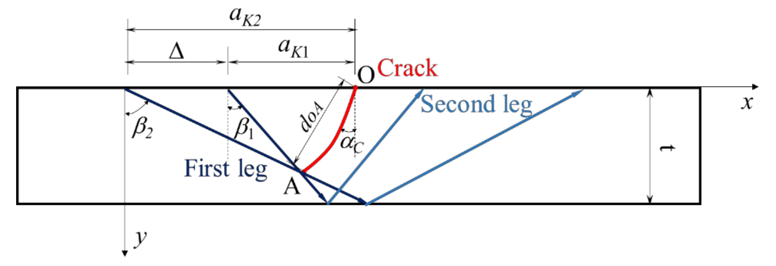
In actual detection work, there is a certain proportional relationship between the received wave height Ra and the maximum wave height Rmax. When the axis of the ultrasonic beam just passes through the crack tip, the ratio of the two is ωK (Equation (2)). According to the maximum wave height received by two sets of probes with different K values (K1 and K2) and the corresponding probe position, the position of the crack tip is determined. The depth dc and deflection angle αc of the crack can be deduced according to their geometric relationship (Equations (3)–(6)). A schematic representation thereof is shown in Figure 2.
ω K = R a R max
β 1 = arctan K 1 β 2 = arctan K 2 Δ = a K 2 a K 1
x 0 = a K 2 , y 0 = 0 x A = cos β 1 sin β 2 sin ( β 2 β 1 ) Δ , y A = cos β 1 cos β 2 sin ( β 2 β 1 ) Δ
d O A = ( x A x O ) 2 + ( y A y O ) 2
α A = arctan x A x 0 y A y 0
where aK1 and aK2 are the distance between the wave incident point and the crack surface point. When the acoustic beam axis passes through the crack tip, β1 and β2 are the included angle between the incident wave and the perpendicular line. x0, y0, xA, and yA are the coordinates of the crack endpoint and Δ is the distance between the two incident points.

3. General Situations of the Test

3.1. Specimens

The specimens were made from Q345qD steel with a thickness of 16 mm. Rectangular grooves with different depths, angles, and widths were manufactured on the bottom of the steel plate to simulate cracks. Three identical rectangular grooves were cut on each plate. The grooves were machined by electrical discharge machining (EDM), taking into account the depth, angle, and width of the crack, as shown in Figure 3. Table 1 lists the main crack parameters, including depth D (3, 5, 7, 9, 11, and 13 mm), width W (0.1, 0.15, and 0.2 mm), and angle α (0°, 10°, 20°, 30°, and 45°). Cracks S-1-1 to S-1-6 are used to study the effect of crack depth on ωK. Cracks S-2-1 to S-2-3 are used to compare the influence of crack width on ωK. Cracks S-3-1 to S-3-12 are used to verify the actual detection effect and accuracy of the method at different angles and depths. The precast crack specimens of flat steel plate are shown in Figure 4.

3.2. Measurement of ωK

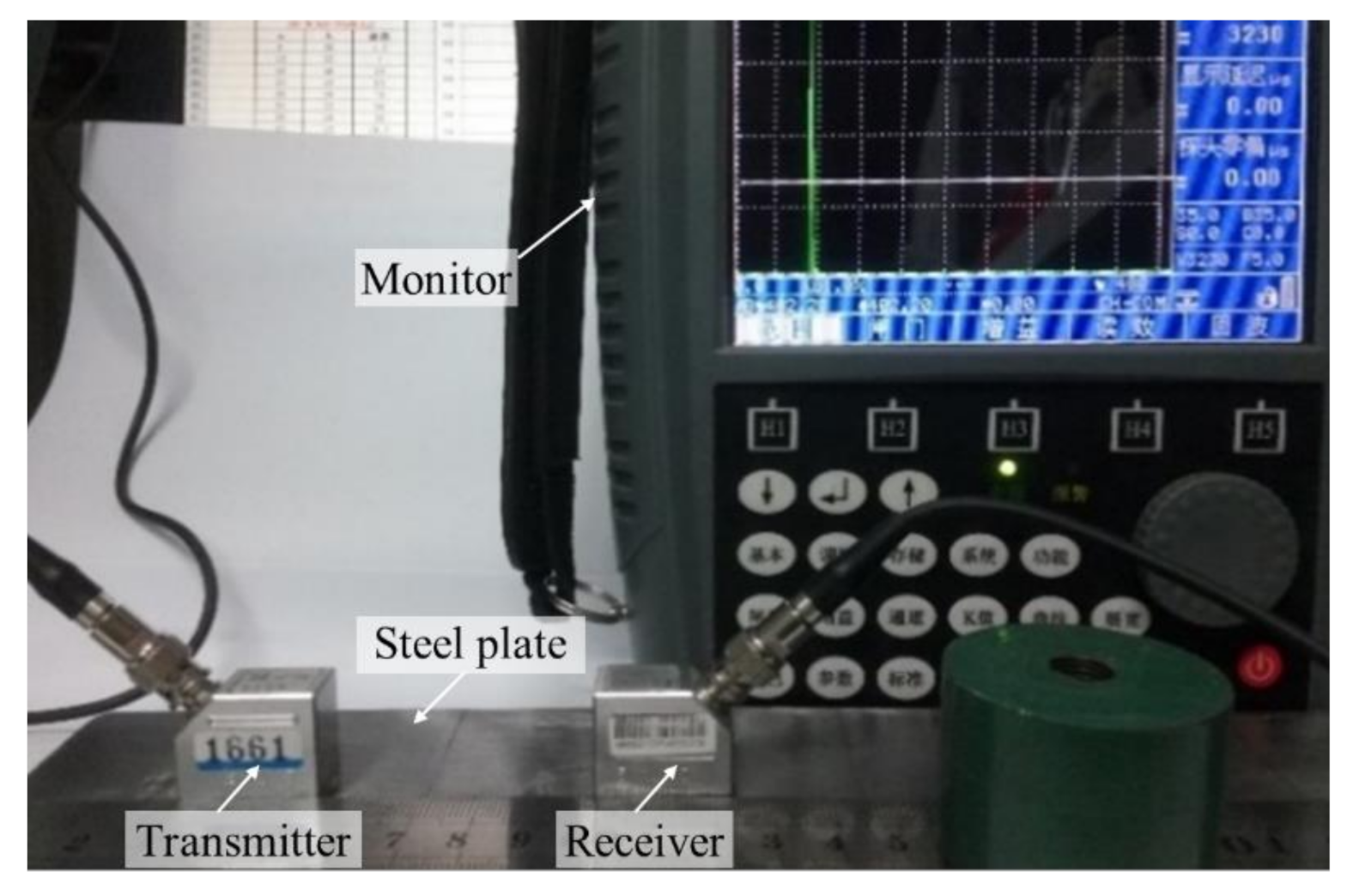
According to the characteristics of fatigue crack formation and propagation in a steel bridge, the SH610 digital ultrasonic flaw detector was selected. In order to cover the crack detection region, two sets of probes with different K value, 0.8 and 2, were selected for the test. Each set of probe contains transmitting and receiving probe, both of which have the same K value. The frequencies used by the probes were between 1.25 and 20 MHz. In this test, a 5 MHz probe was used. The properties of the probe were calibrated on a standard test block before use. The detailed information of probe parameters is shown in Table 2. The experimental setup is shown in Figure 5.
When measuring the value of ωK, the transmitting probe and receiving probe with identical K values were used. According to Equation (1), the distance between the incident point and the receiving point L0 was calculated when the maximum penetrating signal wave was received under crack-free conditions. Keeping the distance between the incident point and receiving point fixed to L0 the distance was taken as the maximum. Taking the distance as the minimum from the crack surface to the incident point when the ultrasonic signal was completely obscured, we kept the two-probe attachment perpendicular to the direction of the crack with changing the distance from the incident point to the crack surface point and recording the wave height at each measuring point. When the maximum wave height was received during the crack detection process, the distance from the probe to the crack surface was L0/2. When the velocity axis just passed through the crack tip, the distance from the probe to the crack surface was L1, which could be calculated by Equation (7). The wave heights Rmax and Ra corresponding to position L0/2 and L1 were found respectively, and ωK values were calculated using Equation (2).
L 1 = K d
where K is the K value of probe and d is the crack depth.
After ωK was determined, the distance between the incident point and the receiving point was maintained. The probe was moved perpendicular to the direction of the crack. The maximum wave height Rmax could be found by scanning across the crack, and the coordinates of the crack tip were obtained by Equation (2). The crack depth and angle were calculated according to Equations (3)–(6).

4. Influence of ωK

4.1. Crack Depth

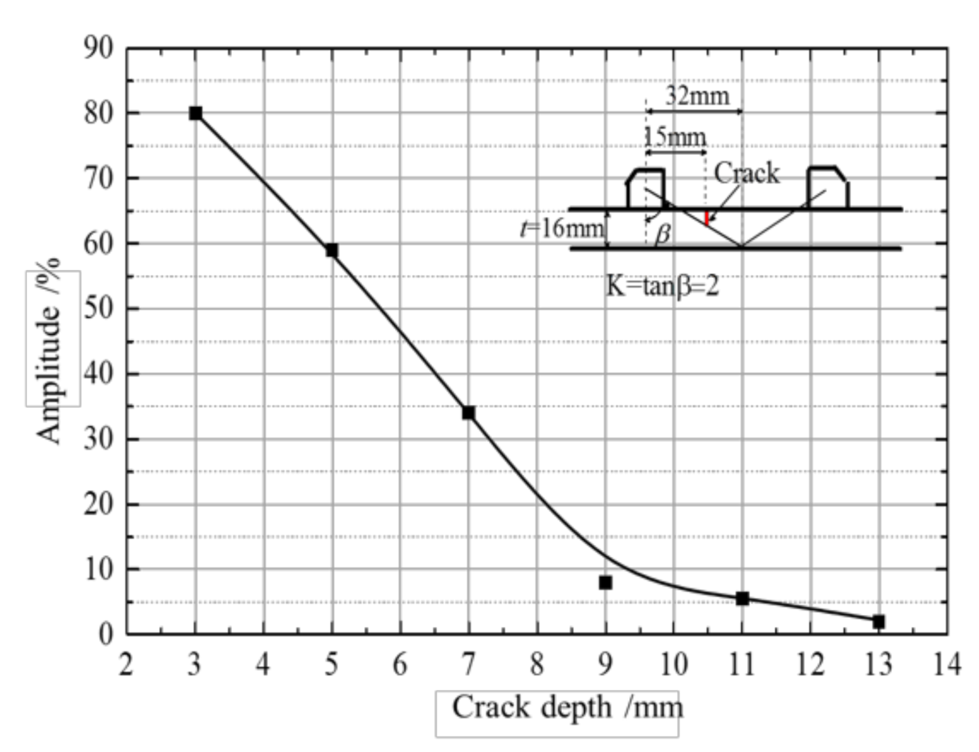
Six prefabricated cracks (C-1 to C-6) were selected to analyze the effects of crack depth. The K value of the probe was 2 and the gain was 35 dB. The relationship between crack depth and wave height is shown in Figure 6. With an increased internal crack depth of the welding seam, the acoustic wave intensity at the receiving probe decreased, and the wave height decreased.
According to Equations (1) and (7), the probe position can be calculated. Then the maximum wave height Rmax corresponding to different crack depths and the wave height Ra at which the beam axis passes through the crack tip could be obtained. As shown in Table 3, the ωK value of probe K2 was calculated using Equation (2). From Table 3, it may be seen that the wave height of the crack tip decreased with increasing crack depth, which conformed to the trend in the crack depth-wave height curve (Figure 5). The ratio of the wave height at the crack tip to the maximum wave height ωK had a certain proportional relationship. The value of ωK decreased slightly with the increase of the crack depth, and the average value was approximately 0.33.

4.2. Crack Width

Three prefabricated cracks (C-5, C-23, and C-24) were selected for analysis. The K value of the probe was 2 and the gain was 35 dB. Table 4 lists the maximum wave height and crack tip wave height for different crack widths. The results show that the maximum wave height and crack tip wave height were about 75% and 25% respectively. The values were unaffected by crack width, and the average value of the ratio ωK was approximately 0.34.

4.3. Probe K Value

In combination with the results and analysis in Section 3.1, the probe with a K value of 0.8 was selected to analyze wave heights from six prefabricated cracks (C-1 to C-6). The tested ωK values were compared with that of the probe with a K value of 2. The influence of different K values ωK was analyzed (Table 5). From Table 5, it may be seen that the ωK value calculated by probes with different K values was different: when K was 0.8, the ωK value increased with increasing crack depth, and the average value was approximately 0.43. When K was 2, the ωK value decreased with increasing crack depth, and the average value was approximately 0.34. Therefore, a reasonable probe K value should be selected according to the structural details of the test before using any ωK value to judge the crack tip position.

5. Error Analysis

5.1. Crack Parameters

To judge the accuracy of the double-probe penetration detection method, the average value of ωK under two different K values was used as the corresponding standard value. The product of this value and the maximum wave height was used as the wave height of the crack tip and thus detected the Cracks S-3-1 to S-3-15. After obtaining the location of the crack tip, the depth and angle of each prefabricated crack were calculated using Equations (3)–(6). The error analysis is summarized in Table 6. Due to uncontrollable factors such as test operation, the crack angle error in some specimens was large, so these data were not considered in the error analysis.
As shown in Table 6, the relative error of crack depth detection was less than 25%. When the deflection angle was between 10 and 30°, the detection precision rose with increasing crack depth. During crack angle detection, the relative errors were all within 30%: it can be inferred from the several cracks with large angle test errors that the crack with a deviation angle similar to the angle of incidence of the wave from the probe (30° or 45°) was nearly parallel to the incidence wave, which also affected the accuracy of penetration detection.

5.2. Penetration Method and the Pulse Reflection Method

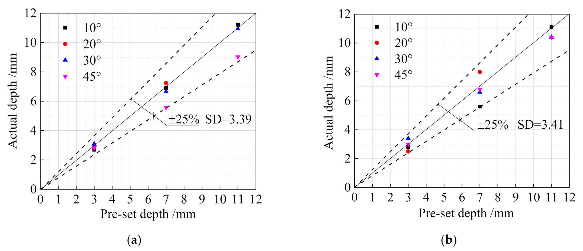
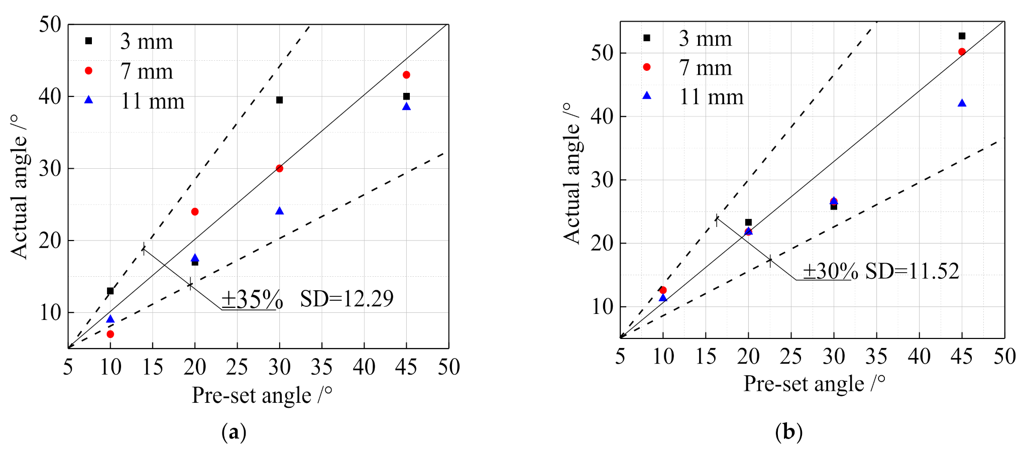
To analyze the error in the double-probe penetration detection method in crack detection, the pulse reflection method was used to detect the depth and angle of prefabricated cracks in flat plate specimens, and the detection accuracy of crack depth and angle under the two methods was compared. The detection errors under the two methods are shown in Figure 7 and Figure 8. As shown in Figure 7, the relative error of the pulse reflection method for crack depth detective was less than 25%, and the mean square deviation (SD) of the two methods was 3.39 and 3.41, respectively. There were no significant differences between them. For deep cracks, the accuracy of the penetration method was greater than that when using the pulse reflection method. In Figure 8, the relative error of the pulse reflection method for the crack angle was less than 35%, and the mean square deviation (SD) of the detection results was 12.29. Compared with the penetration method, the detection accuracy of the pulse reflection method was lower and the detection results were more discrete.
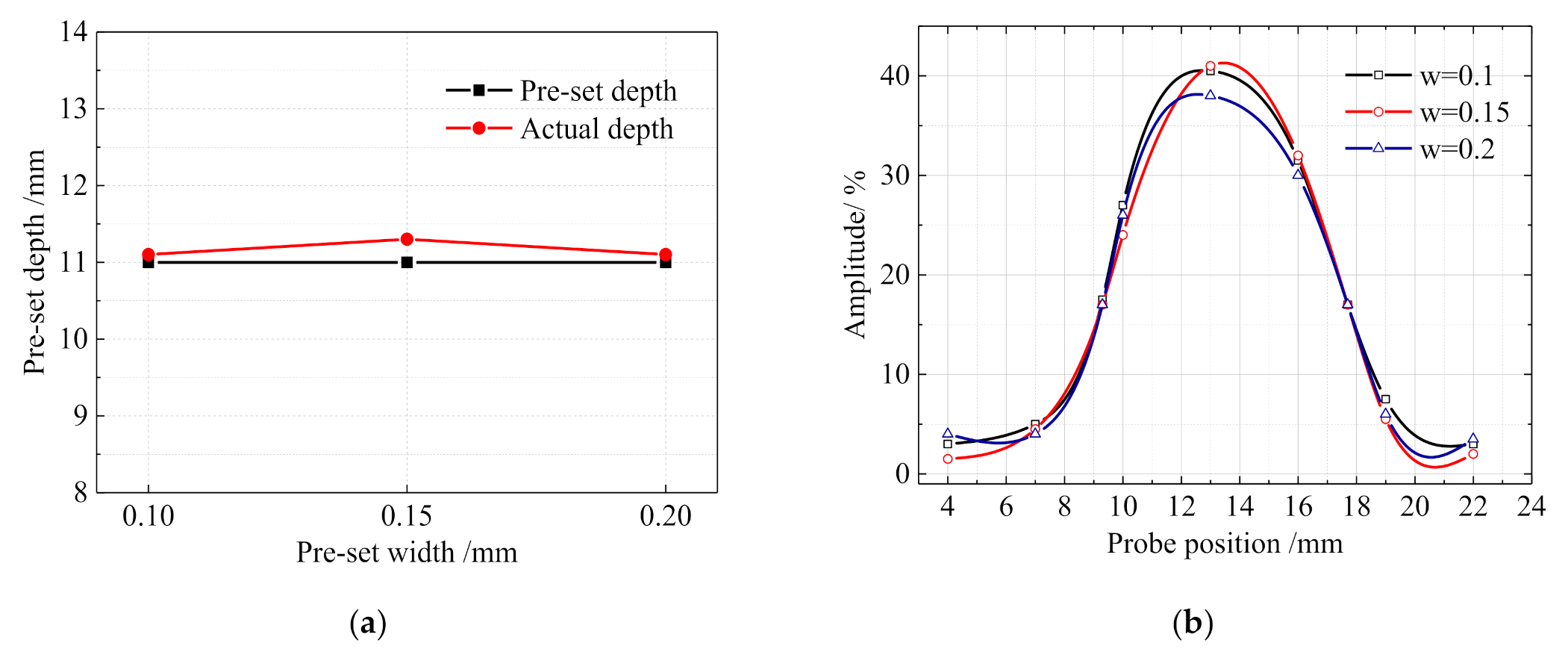
The results of crack width detection using both methods are shown in Figure 9. From Figure 9a, the test results arising from the use of the pulse reflection method were affected by the crack width. When the crack width increased, the crack detection accuracy first decreased, then increased. The detection precision at a crack width of 0.1 mm was similar to that at 0.2 mm: that at a width of 0.5 mm was the lowest. The crack width detection results, achieved using the penetration method, are shown in Figure 9b: the position of the incident point for penetration detection and wave height curves of the three kinds of width cracks was similar. It can be assumed that the crack width did not influence penetration detection. The effect of crack width could be neglected when using the double-probe penetration detection method.

6. Weld Inspection Application

6.1. Feasibility Analysis

To facilitate the theoretical analysis of wave propagation in complex components, the finite-element model of the rib-to-deck component was established by the ABAQUS software explicit dynamics module. Based on the established model, the propagation of the ultrasonic wave in components was simulated and analyzed. According to the analysis results, the feasibility of the double-probe penetration method for detecting rib-to-deck structure detail was judged.
As shown in Figure 10, the established model for the simulation of the crack-free specimen consists of two parts: the tested specimen and the probe. For the tested specimen, the thickness of the deck plate was 12 mm, and the thickness of the U-rib plate was 6 mm. The angle between the two plates was 77°. In addition, the specimen and probe were simulated by a shell element. The material of the specimen was simulated by steel and the probe material was simulated with Plexiglass. The specimen and probe were divided into quadrilateral grids. Each specimen element was set as 0.06 mm and the probe elements were set as 0.02 mm. The bottom surface of the probe model was connected with the detected surface by a tie. Absorption layer was set at the model boundary. Each of the three plate boundaries of the steel member was set with 40 damping absorption layers, and the thickness of each single absorption layer was 0.06 mm. Some 55 damping absorption layers were set on each of the three surfaces of the probe model, and the thickness of the single-layer absorption layer was 0.02 mm.
The propagation process of the wave in the rib-to-deck specimen was analyzed by waveform displacement nephogram. The simulated wave propagation routes are shown in Figure 11. Figure 11a shows the schematic diagram of sound waves in the probe. The wafer normally emits longitudinal waves: when the P-wave meets the reflection from the bottom surface of the probe, waveform conversion occurs. When the wave meets the bottom surface of the specimen, the P-wave meets the bottom surface, reflects and converts, generating a reflected P-wave (L-L) and reflected S-wave (L-S; Figure 11b). When the wave propagates through the weld (Figure 11c), propagating to the U-rib and roof. The point of receipt of the first reflection of the U-rib external wall is where the receiving probe receives the maximum wave height, as shown in Figure 11d. According to the propagation process of the ultrasonic wave in the rib-to-deck in the above model, the simulation resulted in a model waveform along with the actual law of sound wave propagation. Thus, the double probe penetration method could be successfully used to detect the structural details of rib-to-deck.

6.2. Experimental Verification

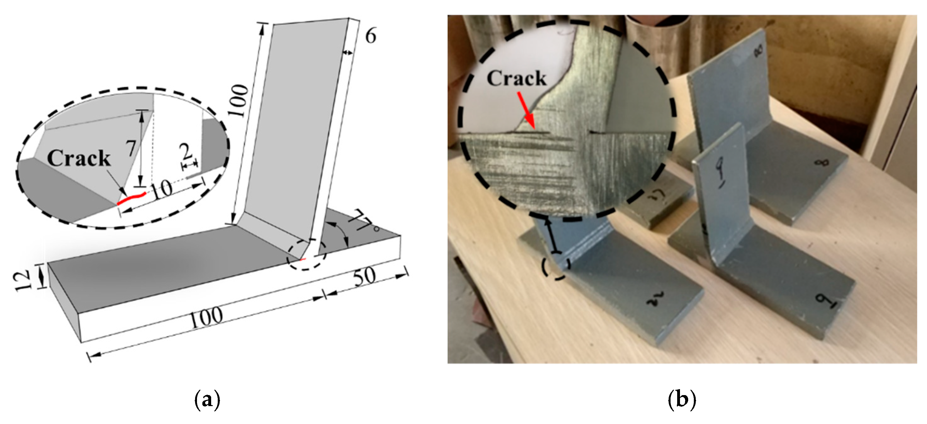
The double probe penetration method can be used to detect the crack of rib-to-deck by finite element analysis simulation. Three rib-to-deck specimens with prefabricated cracks were fabricated to verify the applicability of ultrasonic penetration techniques in this section. The thicknesses of the deck roof parts were 12 mm. The thickness of the U-rib was 8 mm. The width of the specimen was 60 mm and 120 mm. The prefabricated cracks were initiated in the weld root of the specimen and expanded in the direction of the weld root inside the weld. The crack length was 20 mm, 35 mm and 50 mm respectively. The specimen size was shown in Figure 12 and Table 7.
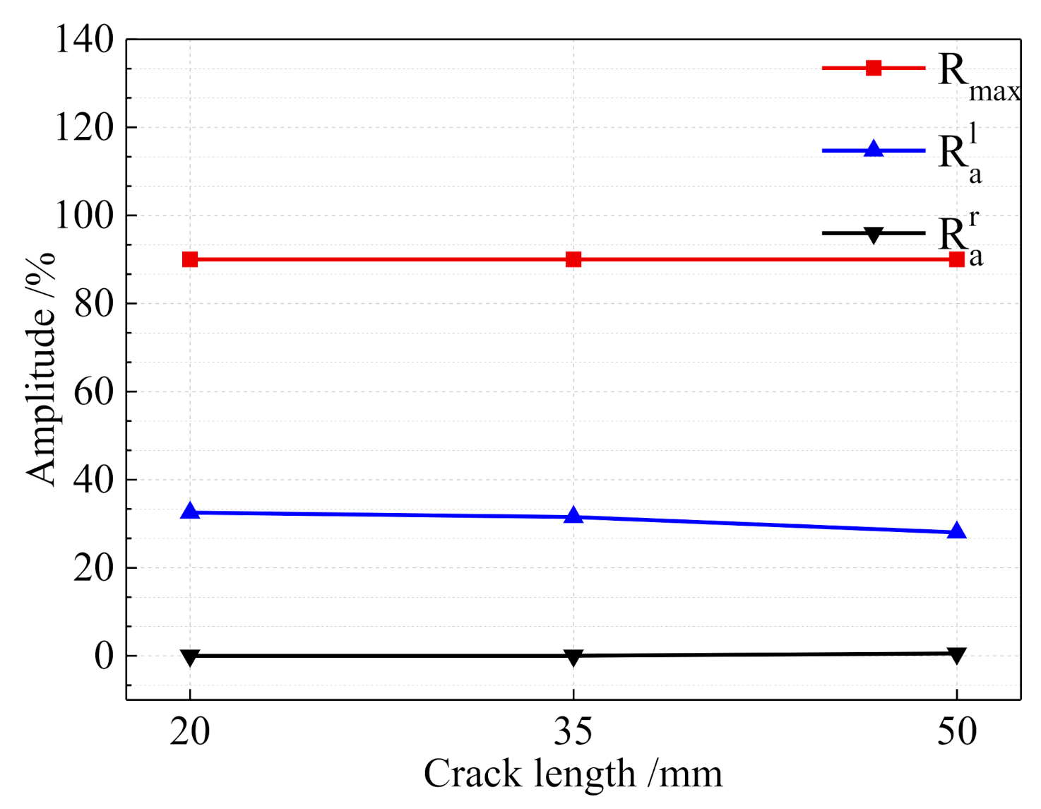
The K value of probes was selected as 0.8 here. The transmitting probe and receiving probe were placed on the deck and U-rib respectively, and the two probes were kept moving in the direction of the vertical welding line. The wave heights at the crack-free and crack tip of the same specimen were measured, and the results were shown in Figure 13. It can be seen from the figure that the wave height of the crack tip was about 30% for the three kinds of cracks of different lengths and the maximum wave height at the crack-free position was 90%.
There is a certain proportional relationship between the wave heights at the crack tips and the wave heights without cracks. The ratio of the two was approximately 0.33. The conclusion was consistent with the test results from flat plate specimens.

7. Conclusions

A method of ultrasonic double-probe penetration detection for cracks in steel structures is presented. The method was verified by the test of the precast cracked flat steel plate specimens. The feasibility of this method in weld crack detection was validated by the ultrasonic finite element simulation model and test results. The main conclusions were as follows:
(1)
The ratio of wave height of crack tip to maximum wave height without a crack ωK was related to the K value of the chosen probe, while the influence of crack depth and width could be ignored.
(2)
The double-probe penetration method had high detection accuracy for the crack depth and angle. Compared with the single-probe pulse reflection method, the detection accuracy for crack angle was improved by nearly 5%, and the discreteness was reduced, which could meet the needs of engineering practice.
(3)
The finite element analysis shows that the double probe penetration method could be used to detect the rib-to-deck detail. The experimental testing results showed that the ωK value of the rib-to-deck weld was consistent with the test results from flat steel plate specimens, which verified the feasibility of the double-probe penetration method for crack detection around rib-to-deck weld details.

Author Contributions

Conceptualization, X.C. and Z.Y.; methodology, X.C. and Z.Y.; formal analysis and investigation, X.C.; writing—original draft preparation, X.C.; writing—review and editing, Z.Y.; resources, B.H.J.; supervision, J.Y.X.; validation, J.X.W. All authors have read and agreed to the published version of the manuscript.

Funding

This work was supported by the National Key Research and Development Project (No. 2017YFE0128700).

Conflicts of Interest

The authors declare no conflict of interest.

References

  1. Guo, T.; Li, A.; Wang, H. Influence of ambient temperature on the fatigue damage of welded bridge decks. Int. J. Fatigue 2008, 30, 1092–1102. [Google Scholar] [CrossRef]
  2. Xiao, Z.G.; Yamada, K.; Ya, S.; Zhao, X.L. Stress analyses and fatigue evaluation of rib-deck joints in steel orthotropic decks. Int. J. Fatigue 2008, 30, 1387–1397. [Google Scholar] [CrossRef]
  3. Fu, Z.; Wang, Y.; Ji, B.; Jiang, F. Effects of multiaxial fatigue on typical details of orthotropic steel bridge deck. Thin Walled Struct. 2019, 135, 137–146. [Google Scholar] [CrossRef]
  4. Guo, T.; Liu, Z.; Correia, J.; de Jesus, A.M. Experimental study on fretting-fatigue of bridge cable wires. Int. J. Fatigue 2020, 131, 105321. [Google Scholar] [CrossRef]
  5. Dinda, S.K.; Warnett, J.M.; Williams, M.A.; Roy, G.G.; Srirangam, P. 3D imaging and quantification of porosity in electron beam welded dissimilar steel to Fe-Al alloy joints by X-ray tomography. Mater. Des. 2016, 96, 224–231. [Google Scholar] [CrossRef]
  6. Huggett, D.J.; Dewan, M.W.; Wahab, M.A.; Okeil, A.; Liao, T.W. Phased array ultrasonic testing for post-weld and online detection of friction stir welding defects. Res. Nondestruct. Eval. 2017, 28, 187–210. [Google Scholar] [CrossRef]
  7. Li, Z.; Haigh, A.; Soutis, C.; Gibson, A.; Sloan, R. A simulation-assisted non-destructive approach for permittivity measurement using an open-ended microwave Waveguide. J. Nondestruct. Eval. 2018, 37, 39. [Google Scholar] [CrossRef] [Green Version]
  8. Rashidyan, S.; Ng, T.T.; Maji, A. Practical aspects of nondestructive induction field testing in determining the depth of steel and reinforced concrete foundations. J. Nondestruct. Eval. 2019, 38, 19. [Google Scholar] [CrossRef]
  9. Hayes, C. The ABC′s of nondestructive weld examination. Weld. J. 1997, 76, 46–51. [Google Scholar]
  10. Cacciola, M.; Morabito, F.C.; Versaci, M. Ultrasonic and Advanced Methods for Nondestructive Testing and Material Characterization; World Scientific: Singapore, 2007. [Google Scholar]
  11. Wohlschlögel, M.; Gläßel, G.; Sanchez, D.; Schüßler, A.; Dillenz, A.; Saal, D.; Mayr, P. Characterization of Nitinol Laser-Weld Joints by Nondestructive Testing. J. Mater. Eng. Perform. 2015, 24, 4991–4996. [Google Scholar] [CrossRef]
  12. Lopez, A.B.; Santos, J.; Sousa, J.P.; Santos, T.G.; Quintino, L. Phased array ultrasonic inspection of metal additive manufacturing parts. J. Nondestruct. Eval. 2019, 38, 62. [Google Scholar] [CrossRef]
  13. Macias, G.G.R. Long Range Crack Detection in the Welded Girder-Diaphragm Connection. Ph.D. Thesis, New Mexico State University, Las Cruces, NM, USA, 1997. [Google Scholar]
  14. Ng, C.C. The Relationship between Ultrasonic Signal and Fatigue Crack Surface Contact in Mild Steel Plate Specimen. Ph.D. Thesis, University of Alberta, Edmonton, AB, Canada, 1998. [Google Scholar]
  15. Franklin, R. Innovative Ultrasonic Methodology for Fatigue Crack Detection in Steel Members. Ph.D. Thesis, West Virginia University, Morgantown, WV, USA, 1998. [Google Scholar]
  16. Harri, K.; Patrick, G.; Steve, V. On-line damage detection on a wing panel using transmission of multisine ultrasonic waves. NDT E Int. 2008, 41, 312–317. [Google Scholar] [CrossRef]
  17. Harara, W.; Ahmad, A. Attempt Towards the Replacement of Radiography with Phased Array Ultrasonic Testing of Steel Plate Welded Joints Performed on Bridges and Other Applications. Russ. J. Nondestruct. Test. 2018, 54, 335–344. [Google Scholar] [CrossRef]
  18. Shirahata, H.; Miki, C.; Yamaguchi, R.; Kinoshita, K.; Yaginuma, Y. Fatigue crack detection by the use of ultrasonic wave height change with crack tip opening. Weld. World 2014, 58, 681–690. [Google Scholar] [CrossRef]
  19. Bakker, M.C.M.; De Jong, F.B.P. Ultrasonic underside inspection for fatigue cracks in the deck plate of a steel orthotropic bridge deck. Heron Engl. Ed. 2003, 48, 277–296. [Google Scholar]
  20. An, Y.-K.; Homin, S.; Hoon, S. Wireless ultrasonic wavefield imaging via laser for hidden damage detection inside a steel box girder bridge. Smart Mater. Struct. 2014, 23, 095019. [Google Scholar] [CrossRef] [Green Version]
  21. Pahlavan, L.; Gerrit, B. Fatigue crack sizing in steel bridge decks using ultrasonic guided waves. NDT E Int. 2016, 77, 49–62. [Google Scholar] [CrossRef]
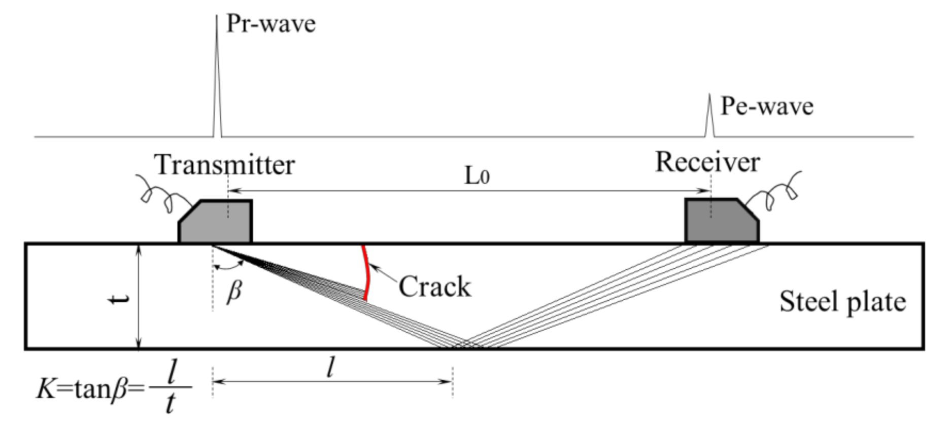
Figure 1. Diagram of the double-probe penetration method.
Applsci 10 08436 g001
Figure 2. Diagram of determining the crack depth and angle by the geometric relation method.
Applsci 10 08436 g002
Figure 3. Diagram showing salient crack parameters.
Applsci 10 08436 g003
Figure 4. Plate prefabricated crack specimen.
Applsci 10 08436 g004
Figure 5. Experimental setup.
Applsci 10 08436 g005
Figure 6. Crack depth wave height curve.
Applsci 10 08436 g006
Figure 7. Error analysis of crack depth measurement. (a) Pulse reflection method and (b) penetration detection method.
Applsci 10 08436 g007
Figure 8. Error analysis of crack angle measurement. (a) Pulse reflection method and (b) penetration detection method.
Applsci 10 08436 g008
Figure 9. Error analysis of crack width measurement. (a) Pulse reflection method and (b) penetration detection method.
Applsci 10 08436 g009
Figure 10. Finite-element model of the rib-to-deck weld.
Applsci 10 08436 g010
Figure 11. Wave propagation in a rib-to-deck specimen. (a) Waves travel through the probe; (b) waves reflect off the bottom of the component; (c) waves travel through the weld and (d) waves travel through the U-ribs.
Applsci 10 08436 g011
Figure 12. Sample details. (a) The dimension of the cracked sample and (b) artificial crack.
Applsci 10 08436 g012
Figure 13. Wave height at various measurement points for different crack lengths.
Applsci 10 08436 g013
Table 1. Environmental and paving parameters for thermal analysis.
SpecimenCrack
Number
Depth
d/mm
Angle
α
Length
L/mm
Width
w/mm
xOA/mmyOA/mmMeasured Depth dOA/mmMeasured Angle α
PlateS-1-130700.2----
S-1-250700.2----
S-1-370700.2----
S-1-490700.2----
S-1-5110700.2----
S-1-6130700.2----
S-2-1110700.1----
S-2-2110700.15----
S-2-3110700.2----
S-3-1310700.25.32.62.816.7
S-3-2710700.210.04.95.612.6
S-3-31110700.222.110.911.111.3
S-3-4320700.20.80.42.223.3
S-3-5720700.214.97.48.021.8
S-3-61120700.223.611.712.521.8
S-3-7330700.26.83.43.725.8
S-3-8730700.212.05.96.626.6
S-3-91130700.218.99.410.426.6
S-3-10345700.22.21.13.052.7
S-3-11745700.28.84.46.850.2
S-3-121145700.215.37.610.442.0
Rib-to-deckS-4-1Penetrated0200.2----
S-4-2Penetrated0350.2----
S-4-3Penetrated0600.2----
Table 2. Probe parameters.
Group NumberThe Number of ProbeFrequency/MHzSize of Chip/mmCalculated K ValueReal K ValueLength of Probe Frontier/mm
11 (transmitting)54 × 40.80.784.55
2 (receiving)54 × 40.80.845.08
23 (transmitting)58 × 921.929.65
4 (receiving)58 × 921.929.91
Table 3. ωK values corresponding to different crack depths.
TestsCrack Depth/mm
35791113
Ra/%302829262526
Rmax/%838486808082
ωK0.3610.3420.3460.3250.3150.315
Table 4. ωK values corresponding to different crack widths.
TestsCrack Width/mm
0.10.150.2
Ra/%26.52525
Rmax/%74.57674
ωK0.3550.3280.338
Table 5. ωK values corresponding to different probe K values.
Crack Depth/mmK = 2K = 0.8
Ra/%Rmax/%ωKAverage ωKRa/%Rmax/%ωKAverage ωK
330830.3610.3418.5450.4090.43
528840.34217.6440.400
729860.34618.2440.414
926800.32518.2400.456
1125800.31515.4350.440
1326820.31517.9360.497
Table 6. Crack parameter error analysis.
Crack NumberCrack ParametersTest ResultsMeasurement ErrorRelative Error
Depth d/mmAngle αDepth d/mmAngle αd/mmΔαδd/%δα/%
S-3-13102.816.70.2−6.76.67-
S-3-27105.612.61.4−2.620.0026.00
S-3-3111011.111.3−0.1−1.30.9113.00
S-3-43202.223.30.8−3.3-16.50
S-3-57208.021.8−1−1.814.299.00
S-3-6112012.521.8−1.5−1.813.649.00
S-3-73303.721.8−0.75.823.3319.33
S-3-87306.626.60.43.45.7111.33
S-3-9113010.426.60.63.45.4511.33
S-3-103453.069.70−7.70.0017.11
S-3-117456.850.20.2−5.22.8611.56
S-3-12114510.442.00.635.456.67
Table 7. The parameters of the crack of deck-to-U-rib.
Crack NumberCrack Width/mmCrack Length/mmCrack Depth/mmDeck Width/mm
T-10.220Full cracking to weld root60
T-20.235120
T-30.250120
Publisher’s Note: MDPI stays neutral with regard to jurisdictional claims in published maps and institutional affiliations.