Abstract
The use of composite materials to strengthen masonry structures has become common practice within the civil engineering community. Steel-reinforced grout (SRG), which comprises high-strength steel fibers embedded in a mortar matrix, is part of the family of the fiber-reinforced cementitious matrix (FRCM) composites that represent a suitable alternative to fiber-reinforced polymer (FRP) composites for strengthening existing structures. Although studies on FRCMs have already reached a certain level of maturity, some key issues remain open, such as the role of matrix type and layout, substrate properties, and test rate. This paper focuses on some of these issues. The results of single-lap direct shear tests on masonry blocks strengthened with SRGs are presented to analyze the bond behavior between the composite material and the substrate. Four aspects are considered: (1) the change in the width of the SRG mortar matrix while keeping the width of the fiber sheet fixed; (2) the type of mortar used for the SRG; (3) the influence of the test rate, and (4) the type of substrate (i.e., concrete vs. masonry). The results obtained indicate the active role of the matrix layout and the importance of the test rate, encouraging further investigations to clarify these aspects.
1. Introduction
The use of composite materials for strengthening existing masonry structures is a topic of great interest among civil engineers. Fiber-reinforced polymer (FRP) systems, which belong to the family of composite materials, comprise fibers of different kinds, such as glass, steel, aramid, and carbon impregnated with a polymeric matrix (typically epoxy resin). Although FRPs have been widely used over the past decades to strengthen concrete and masonry structures [1,2,3], there are some disadvantages, mainly associated with the use of epoxy matrices, such as poor performance at high temperatures and poor vapor permeability, high costs, inapplicability on wet surfaces, hazardous fumes for workers, and incompatibility with the substrate. Therefore, a new type of composite with the same type of fibers organized in an open-mesh textile embedded in an inorganic matrix, instead of a polymeric matrix, has been recently employed. Due to their advantages, such as compatibility with different types of substrate and high vapor permeability, these new materials, usually referred to as fiber-reinforced cementitious matrix (FRCM) composites [4], are considered an effective system to strengthen historical masonry structures [5]. When a unidirectional textile made of high strength steel fibers is employed, FRCMs are named steel-reinforced grout (SRG). Numerous experimental campaigns were conducted in the last 15 years to investigate the contribution of externally bonded FRCMs and SRGs to the load-carrying capacity of concrete and masonry members. These studies showed an increase in the bending [6,7,8], shear [9,10,11], and axial capacity [12,13,14] of FRCM/SRG-strengthened reinforced concrete (RC) members that are comparable with the counterparts strengthened with FRPs. Analogously, FRCMs and SRGs were proven to be effective to increase the in-plane and out-of-plane strength of masonry walls (see Figure 1a,b, respectively) [15,16,17], axial strength of masonry columns [18,19,20], and the load-carrying capacity of masonry arches [21,22].
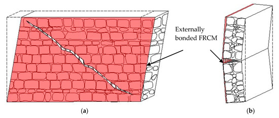
Figure 1.
(a) In-plane and (b) out-of-plane strengthening of masonry walls.
Inorganic-matrix composite materials, which are externally bonded to a concrete or masonry member, usually fail due to composite debonding [4]. Depending on several parameters, such as the matrix and textile type and layout and the properties of substrate and matrix, debonding may occur at different interfaces [23]. For FRCM that feature fibers that are not coated (i.e., not impregnated/sized with organic resin), debonding at the matrix–fiber interface has been frequently reported [24,25,26,27]. In the case of SRG composites, the debonding of the external matrix layer (that covers the fibers) together with the fibers from the internal layer (bonded to the substrate), referred to as matrix interlaminar failure, has been often observed [28,29]. However, both the matrix–fiber debonding and matrix interlaminar failure are affected by the specific strengthening layout, and even changing the number of textile layers may affect the debonding failure observed [30,31]. Furthermore, the test set-up adopted may influence the bond behavior observed. A comparison between the single-lap shear test and modified beam test showed that the composite bond behavior is equally captured by both tests, although in the beam test, two interfaces are involved, and, therefore, the bond of the weakest interface is activated [32]. A similar outcome was found by the authors when a comparison was carried out for FRCMs applied to concrete by conducting single-lap and double-lap tests [33].
The experimental campaign presented in this paper focuses on an important aspect of masonry elements strengthened with SRG composite, i.e., the bond between the composite itself and the substrate. Single-lap direct shear tests are performed on SRG composites bonded to masonry blocks. For SRG, debonding generally occurs with matrix interlaminar failure, but there are some factors that might influence this type of debonding. In this project, some of these factors are investigated, and four parameters are considered to understand how the bond behavior is specifically affected by (1) the type of substrate, (2) the type of SRG mortar matrix, (3) the width of the matrix with respect to the width of the textile, and (4) the test rate. For the first parameter, a few tests with the same composite applied to a concrete block rather than masonry are used as comparison.
2. Materials and Methods
2.1. Materials
Masonry blocks were constructed with solid fired-clay bricks and a nominally low strength mortar for the joints. Nominal dimensions of bricks were 250 mm (length) × 55 mm (width) × 120 mm (depth). The compressive and tensile strength of bricks were evaluated on cylinders of nominal dimensions 50 mm (diameter) × 50 mm (length) cored from the bricks. In total, twenty cylinders were cored: seven cylinders were used to evaluate the tensile strength (fbt), while the remaining thirteen were used to evaluate the compressive strength (fbc) of the bricks. The average value of tensile strength, compressive strength, elastic modulus, and fracture energy (which will be introduced later) of bricks are reported here along with the corresponding coefficient of variation CoV (within parenthesis), which represents a measure of the variability of the results. The tensile strength of bricks was obtained by means of splitting tests, and the average was equal to 3.16 MPa (CoV = 0.12). The average brick compressive strength, evaluated according to CEN EN 772-1 [34], was equal to 20.3 MPa (CoV = 0.17). Among those cylinders used for compression, five were instrumented with two strain gauges applied 180° apart along the circumference of the specimen to measure the elastic modulus (Eb) of bricks. Eb was evaluated on the stress-versus-strain curve obtained as the slope between 5% and 30% of the peak stress. The average elastic modulus Eb obtained was 7.3 GPa (CoV = 0.29) [35]. The fracture energy of bricks (GF) was evaluated by performing three-point bending tests on three notched bricks, as the area under the load-displacement curve divided by the area of the ligament [36,37,38]. The average value of GF was equal to 29.5 N/m (CoV = 0.272) [39].
The compressive strength of mortar joints was evaluated from the compressive strength obtained from the double punch test on fourteen specimens, and the average was equal to 15.9 MPa [35,40].
The SRG composite system used to strengthen the masonry blocks comprised high-strength galvanized steel fibers (cords) embedded in an inorganic mortar matrix. Each cord consisted of five filaments. Three out of the five filaments were straight, and the remaining two filaments were wrapped around the other three with a high torque angle. Cords were arranged in unidirectional sheets mounted on a glass fiber micromesh. The cross-sectional area of the steel cord was 0.538 mm2, and the density of the steel fiber sheet was 670 g/m2 [41]. The mechanical properties of fibers, provided by the manufacturer [41], are reported in Table 1.

Table 1.
Mechanical properties of steel fibers [41].
Two types of mortar were employed for the SRG matrix: a hydraulic lime-based mortar (LM) and a cement-based mortar (CM) matrix. The lime-based mortar matrix was a hydraulic natural lime mortar with fine particles used for structural rehabilitation of existing masonry structures. The flexural strength of this mortar was evaluated according to [42] at 28 days using prisms with nominal dimensions of 40 mm × 40 mm × 160 mm, and the average was equal to 5.0 MPa (CoV = 0.22). The corresponding compressive strength, obtained by compressive tests on the two prisms resulting from the flexural test [42], was equal to 12.3 MPa (CoV = 0.16). The fracture energy, evaluated by means of three-point bending tests [43] on notched beams of dimensions 300 mm (length) × 70 mm (width) × 70 mm (depth), was equal to 30.3 N/m (CoV = 0.22). The second matrix was a cement-based matrix used mainly for the restoration of concrete elements. The flexural strength, compressive strengths, and fracture energy, evaluated with the same methods employed for the lime-based mortar, were equal to 7.6 MPa (CoV = 0.09), 46.4 MPa (CoV = 0.03), and 101.0 N/m (CoV = 0.22), respectively. It should be noted that for both mortars, several batches were used to cast the single-lap direct shear test specimens [35,43]. Therefore, from each batch, three specimens were cast to determine the mechanical properties reported above. The values provided are the average computed for all specimens resulting from the different batches. Results are summarized in Table 2.

Table 2.
Mechanical properties of bricks, lime-based mortar (LM) matrix, and cement-based mortar (CM) matrix.
The effect of the substrate type was investigated by comparing the results of SRG-masonry joints with corresponding SRG-concrete joints with the same SRG strips previously published in [43]. The concrete used for the SRG-concrete joints was part of another experimental campaign, and mechanical properties of concrete were already provided in [43].
2.2. Specimen Preparation and Application of SRG Reinforcement
All masonry blocks were constructed with six layers of half-bricks and five 10 mm-thick mortar joints. Nominal dimensions of blocks were 120 mm (length) × 120 mm (width) × 380 mm (height).
In total, thirty-two masonry blocks were prepared: twenty-seven blocks were strengthened with lime-based mortar SRG, and the remaining five blocks were strengthened with cement-based mortar SRG.
Before applying the composite, all the masonry blocks were left to soak in a bucket filled with water for at least 20 min (Figure 2). This procedure was necessary to avoid water absorption by the masonry surfaces during the application of the SRG composite
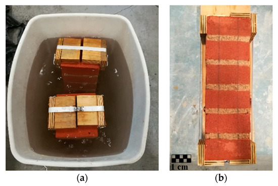
Figure 2.
Preparation of specimen before the application of the steel-reinforced grout (SRG) composite: (a) masonry blocks soak in the water, (b) wet specimen removed from the bucket.
For all masonry blocks, the width of the steel fiber sheet and the bonded length (ℓ) of the SRG strip was maintained constant and equal to 50 mm and 315 mm, respectively. It should be noted that the mortar was used to embed the fibers only in the bonded area. The fibers were left bare outside the bonded area. The width of the mortar matrix was varied: specimens used as reference [35] had a matrix width equal to the width of the steel fiber sheet, i.e., 50 mm. For the remaining blocks, the width of the mortar was increased to 70 mm and 90 mm, while keeping the width of the fiber sheet constant and equal to 50 mm. To avoid the spalling of the first brick of the masonry block, the bonded area started 35 mm from the top edge of the block itself.
In total, three concrete prisms herein reported for the sake of comparison were strengthened with SRG composite [43]. The SRG system bonded to concrete prisms comprised steel fibers embedded in the same cement-based mortar matrix used for masonry.
The procedure followed to bond the SRG composite strip to the substrate was the same for all specimens: (1) delimitation of the bonded area using cardboard; (2) application of the first 4 mm-thick layer of mortar matrix; (3) application of steel fibers, which were gently pressed into the mortar using a trowel; (4) application of the second 4 mm-thick layer of mortar matrix to fully cover the steel fibers (Figure 3). All the specimens were left to cure in the laboratory environment under wet cloths for 28 days.
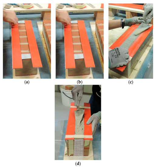
Figure 3.
Phases of application of SRG reinforcement: (a) delimitation of the bonded area; (b) application of the first layer of mortar matrix; (c) application of steel fiber sheet; (d) application of the second layer of mortar matrix.
Specimens were named following the notation DS_A_B_C_D_E_Z where A indicates the bonded length, B refers to the matrix width, C indicates the density of steel fiber (LD = 670 g/m2), D is the matrix mortar employed (LM = lime-based mortar, CM = cement-based mortar matrix), E when present refers to the test rate, and Z is the number of the specimen (see Table 3 and Table 4).

Table 3.
Experimental results in terms of g1 and g2, Pcrit, P*, and failure mode.

Table 4.
Test results of steel-reinforced grout (SRG)-concrete joints [43].
2.3. Single-Lap Direct Shear Test
Bond properties of SRG composites bonded to masonry blocks and concrete prisms were evaluated using the classical push–pull single-lap direct shear test set-up. Tests were conducted under displacement control using a closed-loop servohydraulic universal testing machine with a capacity of 100 kN. The set-up already described in [35] was employed (Figure 3). Two linear variable displacement transducers (LVDTs) were used to control the test. The LVDTs were mounted on the substrate through two holders, and they reacted off of a Ω-shaped aluminum plate mounted on the bare fibers at the beginning of the bonded area (Figure 3). The average of the two LVDTs mounted at the beginning of the bonded area was named global slip (g). The global slip g was increased at a constant rate equal to 0.00084 mm/s (standard test rate). However, for three SRG-masonry joints, the test rate was increased 10 times, i.e. 0.0084 mm/s. It should be noted that the rate employed for the majority of the tests (i.e. 0.00084 mm/s) was previously assessed through an extensive experimental work, and it was concluded that it was adequate to capture the debonding onset and propagation in FRP- and FRCM-concrete joints effectively [44,45]. In this paper, a test rate higher than the standard test rate was adopted to investigate the existence of rate effects on the composite bond behavior and a potential decrease in the amount of time needed to carry out bond tests on this type of material.
A 75 mm-long epoxy tab was constructed at the end of the fiber strip closest to the loaded end to facilitate the gripping of the fibers within the wedges of the testing machine (Figure 4).
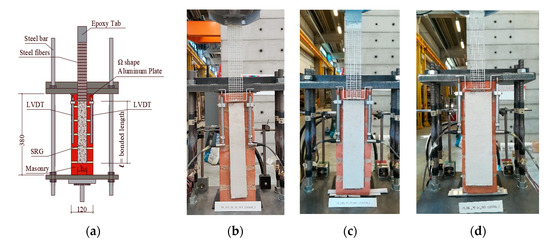
Figure 4.
Single-lap direct shear set-up: (a) sketch of the test set-up; (b) photo of specimen with 50 mm; (c) 70 mm; and (d) 90 mm matrix width.
3. Discussion of Results
This Section provides the results of single-lap direct shear tests in terms of failure mode and load response. Maximum load P*, load-carrying capacity Pcrit, global slips g1 and g2, which will be explained in the following paragraphs, and failure modes are reported in Table 3. The averages of P* and Pcrit, named, and , respectively, are provided in Table 3 for each group, as well.
3.1. Failure Modes
Three failure modes were observed in the direct shear tests:
- Interlaminar failure with debonding at the interface between the internal layer of mortar and steel fibers (MF);
- Rupture of steel fibers (FR);
- Detachment of the SRG strip from the substrate with a thin layer of substrate attached to it in a limited portion (SF).
In general, the most frequent failure mode was interlaminar failure: twenty-five specimens out of thirty-two failed due to the debonding between the internal (i.e., attached to the substrate) layer of mortar and steel fibers (Figure 5a). For masonry blocks with a matrix width greater than that of the steel fibers, when interlaminar failure occurred, it involved only the central part of the SRG composite strip. This means that two lateral portions of mortar remained attached to the masonry substrate (Figure 5b). It should be noted that when the width of the matrix was larger than the width of the fiber sheet, interlaminar failure did not occur for the entire length of the SRG strip (see Table 3). Three masonry blocks out of five with a matrix width of 70 mm and only two out of five with a matrix width of 90 mm, failed due to the rupture of steel fibers (Figure 5c). Therefore, for these specimens, the value of P* was higher than that of other specimens that did not exhibit fiber rupture. The third failure mode was observed only in one specimen, DS_315_50_LD_CM_1, strengthened with a cement-based mortar matrix (Figure 5d). All the blocks tested with a test rate ten times higher than the standard rate [35,46] failed due to the interlaminar failure between the internal layer of matrix and fibers.
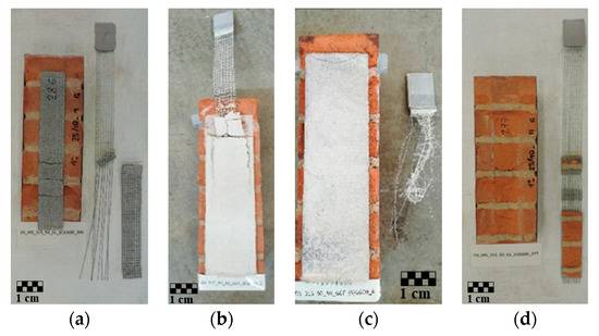
Figure 5.
Failure modes of representative specimens: (a) interlaminar failure with debonding at the interface between the internal layer of mortar and steel fibers (MF); (b) partial interlaminar failure at the interface between the internal layer of mortar and steel fibers (MF*); (c) rupture of fibers (FR); (d) detachment of the SRG strip from the substrate with a thin layer of masonry attached to it (SF).
3.2. Load Responses
The results of single-lap direct shear tests are presented in Figure 6 in terms of applied load (P) versus global slip (g).
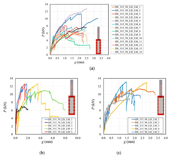
Figure 6.
Load responses of SRG-masonry joints with matrix width equal to: (a) 50 mm [35]; (b) 70 mm; and (c) 90 mm.
3.2.1. Influence of SRG Matrix Width
For fourteen SRG-masonry joints, the width of the SRG matrix was equal to the width of the steel fiber sheet, i.e., 50 mm, and their behavior in terms of P versus g is shown in Figure 6a. The SRG matrix of the remaining blocks had two different widths: Figure 6b shows the results of SRG-masonry joints with matrix width equal to 70 mm, while Figure 6c shows the load response of specimens with the matrix width equal to 90 mm. The load responses were quite scattered even among specimens that belong to the same group, due to the variability of the mortar employed for the SRG matrix [35].
For low values of the load, the P-g curves were approximately linear. As the load increased, a series of load drops occurred, which were associated with the onset of the interfacial crack. For some specimens, after the initial drops, the global slip continued to increase at an almost constant value of the load (plateau). The value of g at the first substantial drop, which corresponds to the beginning of the plateau, is called g1, while the value of g at the end of the plateau is g2, which nominally corresponds to the end of the test. Pcrit is defined in this paper as the average of the load in the interval g1-g2, while P* denoted the maximum load. The distinction between P* and Pcrit was first introduced to distinguish between the load at the onset of the interfacial crack and the average load-carrying capacity of the joint during the propagation of the crack, respectively, in the case of steel-reinforced polymer (SRP) composites [47]. Since the energy required to create a unit-length crack is higher than that required for a unit-length self-similar increase in the crack, P* was generally higher than the corresponding Pcrit for the SRG-masonry joints that showed a plateau in the response.
For twelve SRG-masonry joints, it was not possible to evaluate the Pcrit since, after the first drop of the load, the response continued to increase until failure (see Table 3). Interestingly, for specimens with a matrix width equal to 70 mm and 90 mm, the always-increasing load response (i.e. the lack of a plateau) was associated with fiber rupture. On the other hand, when the matrix width was 50 mm, only one specimen out of four exhibited an always-increasing response that failed due to fiber rupture. This behavior was observed in [35]. The matrix–fiber bond is initially capable of sustaining loads almost close to the fiber rupture, and then a weakness at the matrix–fiber interface triggers the sudden interlaminar debonding. Most likely, the increase in the matrix width is capable of compensating for the presence of weaknesses at the matrix–fiber interface, and fiber rupture is often reached. The average of Pcrit () for specimens with SRG matrix width equal to 70 mm (8.8 kN) increased by 52% with respect to the specimens with a matrix width of 50 mm (5.8 kN). Increasing the matrix width from 50 mm to 90 mm, increased by 69% (9.8 kN). Therefore, increasing the matrix width for a constant fiber width entailed an increase in the load-carrying capacity of the SRG-masonry joint, due to a higher amount of energy required for the crack to initiate and propagate.
The average peak load was greater for specimens with a matrix width equal to 70 mm (=11.2 kN) and 90 mm (=11.4 kN) mm when compared to 50 mm (=7.6 kN), but there was no significant difference between the 70 mm and 90 mm specimens.
3.2.2. Influence of the Type of Matrix
In this Section, load responses of masonry blocks strengthened with cement-based matrix SRG are shown and compared with those of masonry blocks strengthened with lime-based matrix SRG (Figure 7). The matrix width for all the specimens compared in this Section was equal to 50 mm, i.e. it was the same as the width of the fiber sheet. The light green curves represent the masonry blocks strengthened with lime-based matrix SRG (herein called together as DS_315_50_LD_LM_ALL).
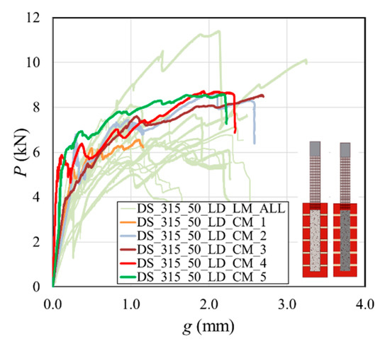
Figure 7.
Comparison of load responses of SRG-masonry joints strengthened with two types of matrix.
For masonry blocks strengthened with cement-based matrix SRG, the initial branch was linear, followed by a non-linear branch with some drops of the load. The first substantial drop of the load corresponded to the onset of the interfacial crack. When the interfacial crack propagated, the load remained almost constant while the global slip increased. The load-carrying capacity was quite consistent among specimens strengthened with cement-based matrix SRG, and the average values of the peak load and load-carrying capacity were = 9.1 kN and = 7.7 kN, respectively.
Compared with specimens with the same matrix width but strengthened with lime-based matrix SRG, of cement-based matrix specimens increased by 33% (7.7 kN versus 5.8 kN), and the average peak load by 20% (9.1 kN versus 7.6 kN). This result was expected as the cement-based matrix has higher mechanical properties (including fracture energy). Indeed, as the matrix between fibers fractures in the interlaminar failure, the load-carrying capacity of the SRG-masonry joint depends on the properties of the matrix itself.
3.2.3. Influence of the Test Rate
Three SRG-masonry joints with lime-based mortar were tested using a test rate (0.0084 mm/s) that was ten times the standard rate (0.00084 mm/s). The load responses obtained were similar to those of specimens tested with the standard test rate (Figure 8). However, when specimens tested with different test rates are compared, it can be observed that increasing the test rate implied an increase in the average peak load by 37% (from 7.6 kN to 10.4 kN).
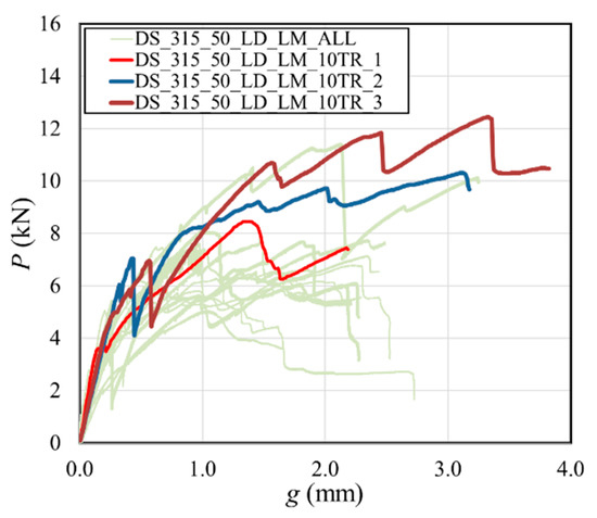
Figure 8.
Comparison of load response of SRG-masonry joints tested with two test rates.
Therefore, even if only three SRG-masonry joints were tested at a higher rate, it appears that a rate effect, which was also observed for para-phenylene benzobisoxazole (PBO) FRCM-concrete joints [46], is present for the type of composite investigated in this paper. However, further work will be needed to understand how the test rate affects the load response, failure mode, and peak load. Figure 8 shows the comparison between specimens tested with the standard rate and specimens tested with a higher test rate. It was decided not to include specimens that presented failure modes other than interlaminar failure. Therefore, the light green curves in Figure 8 are associated with the load responses of all masonry blocks with a matrix width of 50 mm, except for DS_315_50_LD_LM_5, since the failure mode (i.e., fiber rupture, see Table 2) was different from all the other specimens. It should be noted that for the three specimens with a higher rate the plateau load, Pcrit could not be computed, as the load response resembled the always-increasing response observed for other specimens.
As mentioned above, this type of load response was observed for other specimens with the same characteristics and standard test rate, and it is possible that the high rate induced this type of response.
3.2.4. Influence of the Substrate
In addition to SRG-masonry joints, three concrete prisms strengthened with the SRG composite were tested using the same single-lap direct test set-up explained in Section 2.3, for comparison. These tests were part of another experimental campaign [43].
The main results of these tests are reported in Table 4, whereas the corresponding load responses are depicted in Figure 9a. It should be noted that the bonded length ℓ for these three specimens was 200 mm.
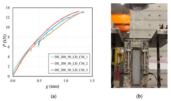
Figure 9.
(a) Load response of SRG-concrete joints and (b) photo of failure mode due to the rupture of steel fibers [43].
A comparison was made with masonry blocks strengthened with the same type of matrix used for concrete prisms, i.e., cement-based mortar matrix, of the same width (50 mm) and the same type of steel fibers. It was noted that instead of interlaminar failure typically observed for the companion masonry specimens, the failure of all concrete prisms was due to the rupture of fibers (Figure 9b). This is particularly important as the bonded length of the SRG-concrete joints was even less than the bonded length of the masonry counterparts. It should be observed that while the masonry surface was not roughened before the application of the SRG, the concrete surface was sandblasted to reach a 4 mm roughness. Thus, the different behavior between masonry and concrete could be linked to the fact that there was an improved adhesion between the internal layer of matrix and concrete substrate, due to the roughness of the substrate itself. The different matrix–substrate bond behavior and the stress field influenced by the roughness may have affected the matrix–fiber interface stress distribution, thus changing the behavior of the specimen. In addition, masonry blocks absorb more water than concrete prisms. Therefore, it is possible (although the blocks were soaked before the application of the SRG [43]) that water absorption by the masonry weakened the matrix and, consequently, the bond between the composite and the substrate.
Figure 9a shows a low dispersion of the experimental curves compared to that of specimens with a lime-based mortar and a masonry substrate (Figure 6) or a different bond behavior when compared to cement-based SRG applied to masonry (Figure 7). FRCMs and SRGs based on hydraulic lime mortar exhibit some inherent variability and results of bond tests are usually quite scattered [35]. For cement-based inorganic-matrix composites, the variability is almost non-existent. Therefore, testing a large number of specimens is pointless. Specifically, for the SRG herein investigated, when a cement-based mortar was used, and it was applied to concrete, the tensile strength of the fibers could be reached, and, therefore, the results were very consistent.
4. Conclusions
Bond behavior between SRG composite and masonry substrate was analyzed by testing masonry blocks strengthened with SRG composites using the classical push–pull single-lap direct shear test set-up. In total, thirty-two masonry blocks were tested. In addition to masonry, three concrete prisms strengthened with the same SRG system were tested for comparison, using the same test set-up.
Three failure modes were observed: interlaminar failure at the matrix–fiber interface, rupture of steel fibers, and detachment of the SRG strip from the substrate with a thin layer of substrate attached to it only in a limited portion.
Four parameters were analyzed to determine their influence: width of the SRG matrix, type of SRG matrix, test rate, and role of the substrate. Test results suggested that:
- Increasing the width of the SRG matrix (without increasing the width of the fibers), from 50 mm to 70 and 90 mm, the average load-carrying capacity Pcrit increased by 52% and 69%, respectively, due to a higher amount of energy required for the crack to initiate and propagate.
- Results of masonry blocks strengthened with cement-based mortar SRG were less scattered with respect to blocks strengthened with lime-based mortar SRG. Compared to specimens with the same matrix width but strengthened with lime-based matrix SRG, the average load-carrying capacity (Pcrit) and peak load (P*) of specimens strengthened with cement-based matrix SRG increased by 33% and 20%, respectively.
- The average peak load of SRG-masonry joints tested at a rate ten times the standard rate increased by 37%. Therefore, it appears that for this type of composite a rate effect might be present.
- Comparing masonry and concrete substrate strengthened with the same SRG system, the mode of failure changed: failure of SRG-concrete joints was due to rupture of steel fibers, while SRG-masonry joints exhibited predominantly interlaminar failure. Therefore, for concrete specimens, it was not possible to evaluate Pcrit. When the averages of peak load P* were compared, the highest average value was observed in concrete specimens since rupture of the fibers occurred.
Author Contributions
Conceptualization, G.B. and C.C.; Methodology, T.D. and C.C.; Investigation, G.B.; Validation, T.D.; Writing—Original Draft, G.B.; Writing—Review and Editing, T.D. and C.C.; Funding acquisition, C.C. All authors have read and agreed to the published version of the manuscript.
Funding
This research received no external funding.
Acknowledgments
Kerakoll S.p.A. of Sassuolo, Italy, is gratefully acknowledged for providing the composite materials.
Conflicts of Interest
The authors declare no conflict of interest.
References
- Bakis, C.E.; Bank, L.; Brown, V.L.; Cosenza, E.; Davalos, J.F.; Lesko, J.J.; Machida, A.; Rizkalla, S.H.; Triantafillou, T.C. Fiber-Reinforced Polymer Composites for Construction—State-of-the-Art Review. J. Compos. Constr. 2002, 6, 73–87. [Google Scholar] [CrossRef]
- Carrara, P.; Ferretti, D.; Freddi, F. Debonding behavior of ancient masonry elements strengthened with CFRP sheets. Compos. Part B Eng. 2013, 45, 800–810. [Google Scholar] [CrossRef]
- Bilotta, A.; Ceroni, F.; Nigro, E.; Pecce, M. Efficiency of CFRP NSM strips and EBR plates for flexural strengthening of RC beams and loading pattern influence. Compos. Struct. 2015, 124, 163–175. [Google Scholar] [CrossRef]
- American Concrete Institute. Guide to Design and Construction of Externally Bonded Fabric-Reinforced Cementitious Matrix (FRCM) Systems for Repair and Strengthening Concrete and Masonry Structures; ACI 549.4R-13; ACI: Farmington Hills, MI, USA, 2013. [Google Scholar]
- Kouris, L.A.S.; Triantafillou, T.C. State-of-the-art on strengthening of masonry structures with textile reinforced mortar (TRM). Constr. Build. Mater. 2018, 188, 1221–1233. [Google Scholar] [CrossRef]
- Wiberg, A. Strengthening of Concrete Beams Using Cementitious Carbon Fibre Composites. Ph.D. Thesis, Royal Institute of Technology, Stockholm, Sweden, 2003. [Google Scholar]
- Napoli, A.; Realfonzo, R. Reinforced concrete beams strengthened with SRP/SRG systems: Experimental investigation. Constr. Build. Mater. 2015, 93, 654–677. [Google Scholar] [CrossRef]
- Bisby, L.A.; Stratford, T.J.; Roy, E.C.; Ward, M. Fibre Reinforced Cementitious Matrix Systems for Fire-Safe Flexural Strengthening of Concrete: Pilot Testing at Ambient Temperatures. In Advanced Composites in Construction (ACIC) 2009 Conference Proceedings; NetComposites Ltd.: Chesterfield, UK, 2009; pp. 449–460. [Google Scholar]
- Ombres, L.; Verre, S. Shear performance of FRCM strengthened RC beams. In Proceedings of the ACI SP-324, 2017 ACI Spring Convention, Detroit, Detroit, MI, USA, 26–30 March 2017; Gianmarco, d.F., Lesley, H.S., Antonio, N., Eds.; 2017; p. 324. [Google Scholar]
- D’Antino, T.; Focacci, F.; Sneed, L.H.; Pellegrino, C. Shear strength model for RC beams with U-wrapped FRCM composites. J. Compos. Constr. 2020, 24, 04019057. [Google Scholar] [CrossRef]
- Younis, A.; Ebead, U.; Shrestha, K.C. Different FRCM systems for shear-strengthening of reinforced concrete beams. Constr. Build. Mater. 2017, 153, 514–526. [Google Scholar] [CrossRef]
- Trapko, T. Fibre Reinforced Cementitious Matrix confined concrete elements. Mater. Des. 2013, 44, 382–391. [Google Scholar] [CrossRef]
- Donnini, J.; Spagnuolo, S.; Corinaldesi, V. A comparison between the use of FRP, FRCM and HPM for concrete confinement. Compos. Part B 2019, 160, 586–594. [Google Scholar] [CrossRef]
- Cascardi, A.; Aiello, M.A.; Triantafillou, T. Analysis-oriented model for concrete and masonry confined with fiber reinforced mortar. Mater. Struct. 2017, 50, 202. [Google Scholar] [CrossRef]
- Babaeidarabad, S.; De Caso, F.; Nanni, A. URM Walls Strengthened with Fabric-Reinforced Cementitious Matrix Composite Subjected to Diagonal Compression. J. Compos. Constr. 2014, 18, 04013045. [Google Scholar] [CrossRef]
- Dong, Z.; Deng, M.; Zhang, Y.; Zhang, C.; Ma, P. Out-of-plane strengthening of unreinforced masonry walls using textile reinforced mortar added short polyvinyl alcohol fibers. Constr. Build. Mater. 2020, 260, 119910. [Google Scholar] [CrossRef]
- Borri, A.; Castori, G.; Corradi, M. Shear behavior of masonry panels strengthened by high strength steel cords. Constr. Build. Mater. 2011, 25, 494–503. [Google Scholar] [CrossRef]
- Cascardi, A.; Micelli, F.; Aiello, M.A. FRCM-confined masonry columns: Experimental investigation on the effect of the inorganic matrix properties. Constr. Build. Mater. 2018, 186, 811–825. [Google Scholar] [CrossRef]
- Sneed, L.H.; Baietti, G.; Fraioli, G.; Carloni, C. Compressive Behavior of Brick Masonry Columns Confined with Steel-Reinforced Grout Jackets. J. Compos. Constr. 2019, 23, 04019037. [Google Scholar] [CrossRef]
- Krevaikas, T.D. Experimental study on carbon fiber textile reinforced mortar system as a means for confinement of masonry columns. Constr. Build. Mater. 2019, 208, 723–733. [Google Scholar] [CrossRef]
- Alecci, V.; Focacci, F.; Rovero, L.; Stipo, G.; De Stefano, M. Intrados strengthening of brick masonry arches with different FRCM composites: Experimental and analytical investigations. Compos. Struct. 2017, 176, 898–909. [Google Scholar] [CrossRef]
- Ramaglia, G.; Lignola, G.P.; Balsamo, A.; Prota, A.; Manfredi, G. Seismic Strengthening of Masonry Vaults with Abutments Using Textile-Reinforced Mortar. J. Compos. Constr. 2017, 21, 04016079. [Google Scholar] [CrossRef]
- National Research Council. Guide for the Design and Construction of Externally Bonded Fibre Reinforced Inorganic Matrix Systems for Strengthening Existing Structures; CNR-DT 215/2018; CNR: Rome, Italy, 2018. [Google Scholar]
- Calabrese, A.S.; Colombi, P.; D’Antino, T. Analytical solution of the bond behavior of FRCM composites using a rigid-softening cohesive material law. Compos. Part B 2019, 174, 107051. [Google Scholar] [CrossRef]
- Lignola, G.P.; Caggegi, C.; Ceroni, F.; De Santis, S.; Krajewski, P.; Lourenço, P.B.; Morganti, M.; Papanicolaou, C.; Pellegrino, C.; Prota, A.; et al. Performance assessment of basalt FRCM for retrofit applications on masonry. Compos. Part B 2017, 128, 1–18. [Google Scholar] [CrossRef]
- D’Ambrisi, A.; Feo, L.; Focacci, F. Experimental and analytical investigation on bond between Carbon-FRCM materials and masonry. Compos. Part B 2013, 46, 15–20. [Google Scholar] [CrossRef]
- Askouni, P.D.; Papanicolaou, C.G. Experimental investigation of bond between glass textile reinforced mortar overlays and masonry: The effect of bond length. Mater. Struct. 2017, 50, 164. [Google Scholar] [CrossRef]
- Sneed, L.H.; Verre, S.; Carloni, C.; Ombres, L. Flexural behavior of RC beams strengthened with steel-FRCM composite. Eng. Struct. 2016, 127, 686–699. [Google Scholar] [CrossRef]
- De Santis, S.; de Felice, G. Steel reinforced grout systems for the strengthening of masonry structures. Compos. Struct. 2015, 134, 533–548. [Google Scholar] [CrossRef]
- D’Ambrisi, A.; Focacci, F. Flexural Strengthening of RC Beams with Cement-Based Composites. J. Compos. Constr. 2011, 15, 707–720. [Google Scholar] [CrossRef]
- Babaeidarabad, S.; Loreto, G.; Nanni, A. Flexural Strengthening of RC Beams with an Externally Bonded Fabric-Reinforced Cementitious Matrix. J. Compos. Constr. 2014, 18, 04014009. [Google Scholar] [CrossRef]
- Calabrese, A.S.; D’Antino, T.; Colombi, P.; Poggi, C. Study of the influence of interface normal stresses on the bond behavior of FRCM composites using direct shear and modified beam tests. Constr. Build. Mater. 2020, 262, 120029. [Google Scholar] [CrossRef]
- Sneed, L.H.; D’Antino, T.; Carloni, C.; Pellegrino, C. A comparison of the bond behavior of PBO-FRCM composites determined by double-lap and single-lap shear tests. Cem. Concr. Compos. 2015, 64, 37–48. [Google Scholar] [CrossRef]
- European Committee for Standardization. Methods of Test for Masonry Units. Part 1: Determination of Compressive Strength; EN 772-1:2011; CEN: Brussels, Belgium, 2011; ISBN 978-0-580-84584-0. [Google Scholar]
- Santandrea, M.; Focacci, F.; Mazzotti, C.; Ubertini, F.; Carloni, C. Determination of the interfacial cohesive material law for SRG composites bonded to a masonry substrate. Eng. Fail. Anal. 2020, 111, 104322. [Google Scholar] [CrossRef]
- Elices, M.; Guinea, G.V.; Planas, J. Measurement of the fracture energy using three-point bend tests: Part 3-influence of cutting theP-δ tail. Mater. Struct. 1992, 25, 327–334. [Google Scholar] [CrossRef]
- Gerstle, W. Progress in Developing a Standard Fracture Toughness Test for Concrete. In Proceedings of the Structures Congress, Orlando, FL, USA, 12–15 May 2010; pp. 1915–1926. [Google Scholar] [CrossRef]
- Hoover, C.G.; Bažant, Z.P. Comprehensive concrete fracture tests: Size effects of Types 1 & 2, crack length effect and postpeak. Eng. Fract. Mech. 2013, 110, 281–289. [Google Scholar] [CrossRef]
- D’Antino, T.; Santandrea, M.; Carloni, C. Advances in Knowledge of the Fracture Properties of Cohesive Materials: Fired-Clay and Tuff Bricks. J. Eng. Mech. 2020, 146, 04020079. [Google Scholar] [CrossRef]
- German Institute for Standardisation. Testing of Mortars Containing Mineral Binders—Part 9: Hardened Mortars—Determination of the Mortar Compressive Strength in the Bed Joint; DIN 18555-9; German Institute for Standardisation: Berlin, Germany, 1999. [Google Scholar]
- Kerakoll, S.p.a. GeoSteel G600. Available online: https://products.kerakoll.com/it-IT/p/geosteel-g600 (accessed on 29 July 2020).
- European Committee for Standardization. Methods of Test for Mortar for Masonry. Determination of Flexural and Compressive Strength of Hardened Mortar; EN 1015-11:1999; CEN: Brussels, Belgium, 1999; ISBN 058035469. [Google Scholar]
- Santandrea, M. Bond Behavior between Fiber Reinforced Composites and Quasi-Brittle Material Interfaces. Ph.D. Thesis, University of Bologna, Bologna, Italy, 2018. [Google Scholar]
- Subramaniam, K.V.; Carloni, C.; Nobile, L. Width effect in the interface fracture during shear debonding of FRP sheets from concrete. Eng. Fract. Mech. 2007, 74, 578–594. [Google Scholar] [CrossRef]
- D’Antino, T.; Carloni, C.; Sneed, L.H.; Pellegrino, C. Matrix–fiber bond behavior in PBO FRCM composites: A fracture mechanics approach. Eng. Fract. Mech. 2014, 117, 94–111. [Google Scholar] [CrossRef]
- Carloni, C.; Verre, S.; Sneed, L.H.; Ombres, L. Loading rate effect on the debonding phenomenon in fiber reinforced cementitious matrix-concrete joints. Compos. Part B 2017, 108, 301–314. [Google Scholar] [CrossRef]
- Carloni, C.; Santandrea, M.; Imohamed, I.A.O. Determination of the interfacial properties of SRP strips bonded to concrete and comparison between single-lap and notched beam tests. Eng. Fract. Mech. 2017, 186, 80–104. [Google Scholar] [CrossRef]
Publisher’s Note: MDPI stays neutral with regard to jurisdictional claims in published maps and institutional affiliations. |
© 2020 by the authors. Licensee MDPI, Basel, Switzerland. This article is an open access article distributed under the terms and conditions of the Creative Commons Attribution (CC BY) license (http://creativecommons.org/licenses/by/4.0/).

