Abstract
Near-fault events can cause severe damage to civil structures, including bridges. Many studies have demonstrated that the seismic assessment is not straightforward. Usually, dealing with near-fault ground motion, the structural analysis is performed using Nonlinear Response-History Analysis (NRHA) but in the last years, many authors have tested existing pushover-based procedures originally developed and validated using far-field events. Between those procedures, the Incremental Modal Pushover Analysis (IMPAβ) is a pushover-based procedure specifically developed for bridges that, in this work, was applied to a case study considering near-fault pulse-like ground motion records. The records were analyzed and selected from the European Strong Motion Database. In the paper the results obtained with IMPAβ together with other standard pushover procedures, are compared with NRHA and incremental dynamic analyses; the vertical component of the motion has been also considered. Results obtained with the bridge case study demonstrate that the vertical seismic action has a minor influence on the structural response and that IMPAβ is confirmed as a very effective pushover-based method that can be applied also for near-fault events.
1. Introduction
Near-field ground motions (NF) differ from ordinary (far-field) ground motions. The proximity to the fault renders the effect of the global displacements and the mutual displacements of the opposite sides of the fault very evident in the records: (i) the vertical motion component maximum values often exceeds the horizontal component [1]; long period velocity pulses can be generated by (ii) earthquake directivity and (iii) fling-step [2], (iv) differential input displacements at the base of the piers [3].
For (i), in structures prone to axial force variation, the combined effect of horizontal and vertical motions can bring to severe structural demand [4].
Case (ii) happens due to the focusing of wave energy along the fault in the direction of rupture, when this latter propagates towards the site (forward directivity) and when the velocity of propagation is slightly slower than the shear wave velocity, causing the seismic energy to arrive in a large pulse of motion [5]. In this case, the pulses in the velocity time series are generally double-sided, and they are stronger in the component of motion normal to the fault strike.
Case (iii) (fling-step) occurs when the earthquake causes major surface rupture. In this case, there is a slow increase of stresses in the earth crust over long periods of time. Then, the stresses are abruptly released causing a permanent offset in the displacement time series [6]. Fling-step effects produce single-sided pulses. For dip-slip faults, also these effects are observed in the component of motion normal to the fault strike.
Case (iv), differential displacements, will not be treated here even though the authors discussed possible input generations and relative effects in various publications [7,8].
Near-fault effects on bridges are usually investigated by means of Nonlinear Response History Analyses (NRHA) [9,10,11,12]. Consequently, a method frequently used to assess the response of structures to NF is Incremental Dynamic Analysis (IDA) [13], which requires the execution of several NRHA using a set of ground motion records. NRHA allows for the proper estimation of the seismic demand and capacity of structures in the time domain considering the horizontal and vertical components of the seismic action (the vertical one is relevant for NF events).
Due to the significant amount of time required for analysis and complexity required to perform several NRHAs and to the specific complexity of the dynamic method, it is useful to investigate alternative static methods that can provide results with lower computational effort. For these reasons, some authors proposed the use of pushover analyses to investigate the response of bridge structures under near-fault seismic input [14,15].
In [16,17,18], the authors of the paper at hand proposed an incremental (in terms of seismic intensity) pushover-based procedure (specifically developed for bridges) named IMPAβ, and discussed the validity in case of far-field records (FF). The procedure employs the envelope of a single-run conventional uniform pushover analysis (UPA) and of a modal pushover analysis (MPA), to determine the seismic demands for each intensity level considered.
In the case of NF ground motions, the vertical action becomes relevant; therefore, its consideration or neglect thereof should be discussed. In this work, this issue has been considered and the necessity of performing vertical and horizontal pushover has been evaluated by testing the IMPAβ procedure substituting MPA with the Extended Modal Pushover Analysis (EMPA) [19], which considers all the components of the records. Nonetheless, as discussed in §2, EMPA results were coincident with MPA.
Scope of the work presented is therefore the evaluation of this innovative procedure proposed for bridges to be proposed also in case of near-fault events. This activity was performed testing a review of the IMPAβ in order to obtain a procedure more suitable for near-fault events. The inclusion of innovative pushover methods (the EMPA) in IMPAβ was tested and discussed, and finally, the original version of the procedure was considered, which, in this case, was the best version of the method. The procedure testing was performed using a set of near-fault ground motion records as input and, the same irregular bridge case study studied in [18] was considered.
In the paper, the seismic demands resulting from IMPAβ are compared to those predicted from incremental dynamic analysis (IDA) as a benchmark solution; standard pushover procedures were tested and compared in order to contribute to a critical review of existing nonlinear static procedure. Therefore, according to IDA, several nonlinear time-history analysis have been performed considering a set of near-fault ground motions (both horizontal and vertical components) whereas, performing IMPAβ, the response spectra of those ground motions have been used for the seismic demand. Several pushover analyses were performed at different increasing intensities and then comparisons were made among the results obtained for the single pushovers and for IMPAβ and the single NRHAs and IDA, respectively. It is worth noting that the spatial variation of motion, causing different motion at the base of the different bridge piers, is not taken into account in this work. This issue, treated by the authors elsewhere [7,8,20], is still under development for incremental pushover and will be finalized in a future publication.
After a short description of IMPAβ procedure (§2), the case study of the selected bridge will be introduced (§3.1), then the selection of the near-fault seismic input will be described (§3.2) and the numerical model will be displayed (§3.3). The execution and results of nonlinear analyses are given in §4, while §5 and §6 provide discussion of the results and conclusions.
2. Short Description of IMPAβ Procedure
It is assumed that NRHA represents the “correct” response evaluation, even for NF input. The incremental modal pushover analysis for bridges (IMPAβ) [18] is carried out and results are compared to IDAs. IMPAβ requires the execution of several pushover analyses according to two different load patterns: a uniform loading profile (UPA) and a modal pushover analysis (MPA) according to the procedure presented in [16,17]. As previously mentioned, the use of EMPA (which includes vertical action) instead of MPA was tested and verified as irrelevant for the scope of the analysis. In EMPA the seismic excitation vector is the sum of three terms, each one corresponding to the components of the accelerogram record. The pushover capacity curve is obtained taking into account the contributions of the cited excitation vector in the considered degrees of freedom (transversal and vertical displacement): two capacity curves were recorded in a single pushover analysis of each mode (the dominant modes associated with the selected directions) and the component along the investigated direction (the transversal for the case study discussed herein) were successively combined according to the SRSS rule in order to obtain the final capacity curve. Nonetheless, the prediction of the structural response of the bridge with EMPA, also for NF events, is close to MPA (the same conclusion is discussed in [19] for the case study performed with FF events) and therefore the original version of IMPAβ, developed and tested considering far-field ground motions (FF), was tested and discussed herein and validated in case of NF.
The irrelevance of the vertical input in the pushover analysis, according to the scope and the results of this paper, is discussed in Section 4.
In addition, in this work a standard pushover analysis (SPA), with a load profile proportional to the dominant modal shape has been performed to compare results from different pushover procedures with NRHA. The IMPAβ procedure can be summarized in the following main steps:
- Definition of seismic demand in terms of a response spectrum (RS);
- Discretization of the intensity range and definition of a set of intensity levels I;
- Traditional pushover analysis adopting a uniform loading profile (UPA);
- Modal analysis of the bridge in order to select the relevant modes;
- Modal pushover analysis for each intensity level and, selection of the performance point (P.P.). Combining what obtained according to a combination rule (e.g., CQC or SRSS) a performance point that can be considered “multimodal” (P.P.m,i) can be defined.
Therefore, IMPAβ requires to perform an incremental modal pushover analysis (IMPA) and an incremental UPA (IUPA). Afterwards, in order to obtain a univocal capacity curve, for each intensity step i, the IMPAβ procedure requires to evaluate the Pi,IMPAβ (Figure 1) according to (1). The capacity curve obtained is therefore an envelope of the results obtained from UPA and MPA.
being:
Pi,IMPAβ = (max (ur,i,MPA;ur,i,UPA); max (Vb,i,MPA;Vb,i,UPA))
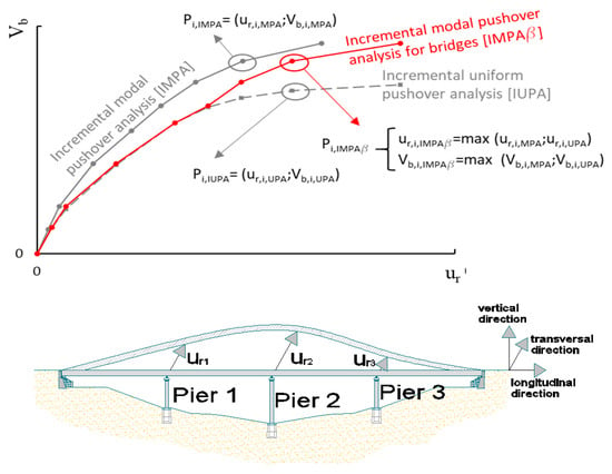
Figure 1.
(Top) Degrees of freedom of the bridge: performing a pushover analysis the displacement ur of the control point (ur is the transversal displacement). (Bottom) Procedure for the definition of the capacity curve of the incremental modal pushover analysis for bridges (IMPAβ) as an envelope of uniform pushover analysis (UPA) and modal pushover analysis (MPA) at each intensity level.
- ur,i,MPA the displacement at the P.P.m,i obtained performing MPA;
- Vb,i,MPA the base shear at the P.P.m,i obtained performing MPA;
- ur,i,UPA the displacement at the P.P.i obtained performing UPA;
- Vb,i,UPA the base shear at the P.P.i obtained performing UPA.
The seismic demand is expressed in terms of Response Spectrum (RS): a RS can be selected and scaled according to different criteria. In the application discussed herein the RS has been derived from the set of near-fault ground motion records selected (§ 3.2). The RS have been linearly scaled to match the desired intensity range.
3. Case Study
3.1. The Case Study
The case study selected is a bridge with a straight deck having a total length of 200 m with four equal spans of 50 m (Figure 2). The case study has been adopted in many previous works published by many authors since the 1990s [21], and also in a recent work in which the IMPAβ [18] has been presented. The bridge is located in Reggio Calabria, Italy, but since in this work we used the strong ground motion records of 2016 Central Italy earthquakes, the actual location of the bridge can be considered Norcia, Italy. The deck of the bridge consists of 14-m-wide pre-cast concrete box girder supported by piers through bearings locked in the transverse direction and, at the abutments, through elastomeric bearings (movement in the longitudinal direction is allowed at the abutments, but transverse displacements are restrained).
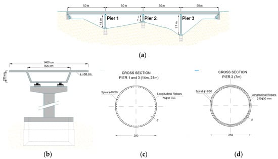
Figure 2.
Structural details of selected bridge: (a) longitudinal view, highlighting the piers and span length; (b) bridge pier, elevation view; bridge pier cross-sections: pier 1 and 3 (c), pier 2 (d).
The three circular piers (P1, P2 and P3), have different heights and a diameter of 2.5 m. The bridge was designed, according to Eurocode 8, using concrete C20/25 and steel B450C; C20/25 has a characteristic compressive cylindric strength of 20 MPa and the B450 a characteristic yield strength of 450 MPa. The design of the bridge was done considering a seismic action with a design peak ground acceleration of 0.35 g and a behavior factor q = 3.0. The design loads adopted for dimensioning the bridge structural elements are listed in Table 1.

Table 1.
Loads and actions.
The response of the bridge model was estimated through the employment of nonlinear static and dynamic analyses. The dynamic analyses were performed adopting a set of ground motions (GM) selected according to the criteria described in §3.2; from the set of ground motions, a median response spectra (RSm) was defined. The GMs were used to perform the NRHAs as well as their mean spectrum (RSm) were used for the purpose of evaluating the pushover-based procedure (the performance point is evaluated, for each intensity level, adopting RSm for the seismic demand).
In this paper, (§4) analysis results are presented in terms of deformed shape of the bridge in transverse direction and bridge capacity curve (i.e., monitoring point displacement versus seismic intensity).
3.2. Selection of Near-Fault Records
The seismic events that hit Italy in 2016 and 2017, known as the Central Italy earthquakes, had been a series of four seismic events occurred in Italy between August and October 2016 [22] with minor events in January 2017. The two major earthquakes were those that occurred on August 24 and October 30, 2016 with magnitudes Mw = 6 and 6.5, respectively. In both cases, many seismic stations close to the epicenters recorded the strong ground motion. In some cases, the records presented typical near-fault pulse-like behavior, as highlighted both in the joint report written by the ReLUIS-INGV Workgroup [23] and reported in the European Strong Motion Database [24]. Table 2 reports the ground motion parameters of the selected records for August 24. The Joyner and Boore distance (Rjb) is the distance from the fault surface projection, and it is reported together with the epicentral distance (Repi).

Table 2.
Ground motion parameters peak ground acceleration (PGA) ad peck ground velocity (PGV) of 24 August 2016 records for the different seismic stations which recorded the earthquake ground motion. Accelerations and velocities are expressed in g and cm/s, respectively. PGA = Peak Ground Acceleration; PGV = Peak Ground Velocity.
The characteristics of the main events were reported by many authors. The study by Luzi et al. [25] reports, among the other pieces of information, the strike of the causative fault of 156 degrees with respect to the North–South direction for the event of August 24. According to these indications, the horizontal records were rotated in order to obtain the Fault Normal and Fault Parallel components of the ground motion. Figure 3 reports the Fault Normal components of the acceleration time series of the selected near-fault ground motion records.
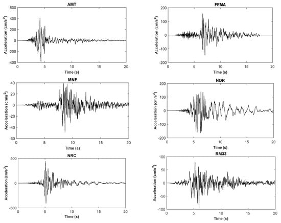
Figure 3.
Fault normal components of the acceleration time series of the selected near-fault ground motion records.
Figure 4 reports the velocity time series (black plots) of the FN components of the 6 seismic stations selected among those which recorded the strong ground motion on 24 August 2016. For each time series, the pulses (red plots) were extracted using the procedure provided by Baker [26]. This method allows to also evaluate the period Tp of the pulse. In addition, the peak-to-peak velocity, as given by the difference between the two peaks in one cycle of motion, was evaluated and reported for each record. This parameter can be more useful than PGV because generally, the pulses generated during near-fault strong motion are double-sided [27].
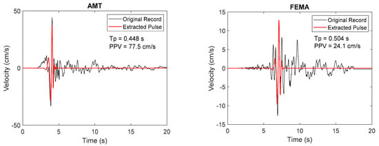
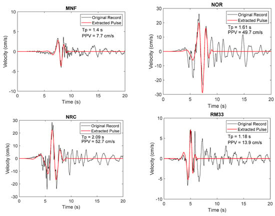
Figure 4.
Velocity time series (black plots) and extracted pulses (red plots) of the fault normal (FN) components of the 6 seismic stations selected among those which recorded the strong ground motion on 24 August 2016.
3.3. Modeling
The software used to model the bridge was SAP2000 NL, v. 21 [28]; the structural scheme used is the same reported in detail in [29] where the case study model was introduced.
The model (Figure 5) has been developed according to Pacific Earthquake Engineering Research (PEER) guidelines [30] and its properties ideally represent the mass distribution, strength, stiffness and deformability of the real bridge. Following the procedure proposed in [30], piers and girders supporting the deck were modelled by 3D frame elements; the box-girder cross section was defined using the SAP 2000 Section Designer that allows to correctly model the real geometry described in Figure 2.
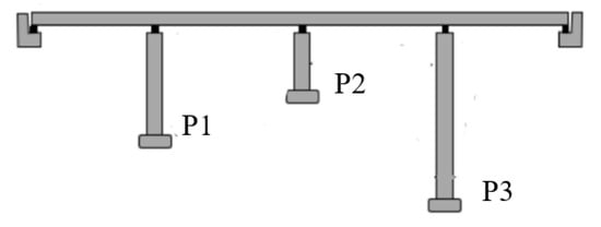
Figure 5.
Bridge structural model.
The connection between the superstructure and the abutment is modeled as a rigid connection in the transversal direction. All the pier elements were modelled with nonlinear properties at the possible yield locations, i.e., plastic regions according to Eurocode 8. The plastic hinges were modelled with SAP2000 fiber (P-M2-M3) hinges. Unconfined concrete was assigned for the concrete cover and confined for the rest of the section; the Mander’s [31] concrete model was used to define confined and unconfined concrete stress–strain relationships whereas the reinforcing steel parameters were assumed given the design parameters of B450C (Fy = 450 Mpa, Es = 210,000 Mpa, Fu = 540 Mpa).
The fiber hinges were defined by moment–rotation curves calculated using a fiber-based model of the cross-section according to the reinforcement details at the hinge locations. The constitutive model adopted for the concrete (both unconfined and confined) is the Mander’s model and the rebar was considered consistently with the code parameters: fy = 450 Mpa, Es = 210,000 Mpa, fu = 540 Mpa. More complex models can be used to describe specific cyclic behavior of RC piers [32] also in the presence of corrosion [33].
3.4. Modal Properties
According to the IMPAβ procedure, a modal analysis of the bridge was performed in order to identify the relevant modal shapes in terms of period and participating mass. Results are summarized in Table 3 (the main mode is the 3rd, T = 0.53 s) and, in Figure 6, the modal deformed shapes of the deck (transversal direction) are plotted. The modes were selected following the indications of [34]; therefore, a lower bound of 3% for the participating mass was considered (modes having a lower value were neglected). The target cumulative participating mass was 90% and, considering mode 2, 3 and 4, the case study reached a value of 92.7%; the neglected modes were characterized by a participating mass lower than 1%. It is worth mentioning that for existing structures, modal characteristics can be retrieved using modal updating techniques [35].

Table 3.
Modal analysis of the bridge: relevant modes in the transversal direction (mode 1, mode 3 and mode 4) having a participating mass ratio > 3%.
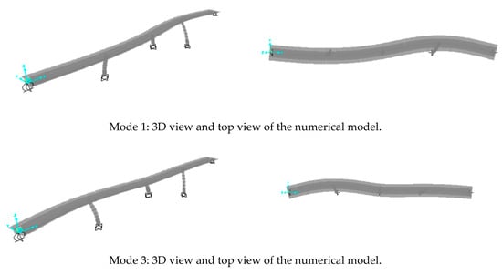
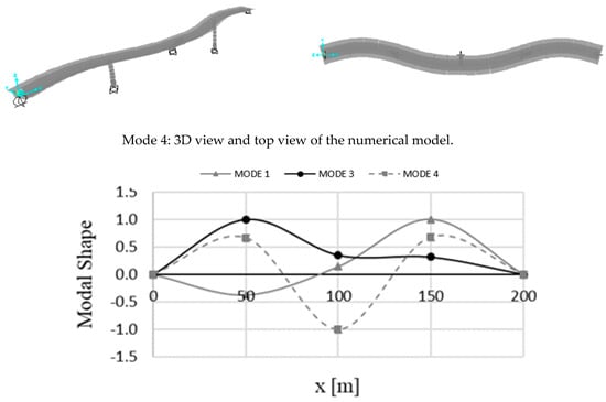
Figure 6.
Bridge modal shape: most relevant modes in the transversal direction.
4. Nonlinear Analyses
The bridge was analyzed at several seismic intensity levels: considering a scale factor from 0.5 to 2.0 being the average PGA of the GM selected 0.32g and being PGA = 0.35 g the design value of the bridge analyzed.
The nonlinear dynamic analyses were preceded by the application of the gravity loads performing a nonlinear static analysis. The nonlinear response-history analysis (NRHA), performed using time increments of 0.1 s, was performed considering both the vertical and the horizontal component (transversal direction) of the ground motion. Among the common methods provided by SAP2000 software for conducting direct-integration time history analysis, the Hibler–Hughes–Taylor alpha (HHT) technique [36,37] was used in this study; the large displacement effects and material nonlinear properties were also considered.
From Figure 7, Figure 8 and Figure 9, the structural response to each GM is plotted in terms of deck displacement (transversal displacement of the deck at Pier 1, Pier 2 and Pier 3) and the variation of the axial load on each pier. The axial load variation is useful to evaluate the relevance of the vertical component of the GM in terms of axial load-bending moment interaction (the hinge of the piers are PM being P = axial load and M = bending moment) and therefore for the structural response; in a pushover analysis this loading variation cannot be considered adopting procedures such as SPA, UPA or MPA. In all the cited pushover methods the analysis is performed starting from a preliminary nonlinear step in which the vertical static loads are imposed. As already discussed in the introduction, in a preliminary phase of this work, the use of EMPA (a modal pushover that includes also the vertical component of the seismic action) as an alternative to MPA was evaluated. This modification of the IMPAβ was discarded because the results, using MPA or EMPA were very similar as discussed below.
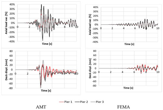
Figure 7.
NRHA with scale factor 1.0 (considering both vertical and transversal components: top). Variation of the axial load (from the static load on piers during the seismic event; bottom). Deck displacements.
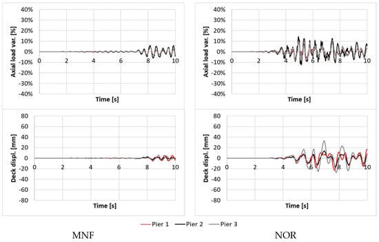
Figure 8.
NRHA with scale factor 1.0 (considering both vertical and transversal components: top) Variation of the axial load (from the static load on piers during the seismic event; bottom). Deck displacements.
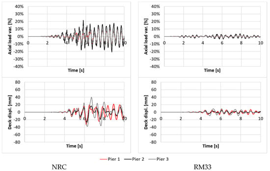
Figure 9.
NRHA with scale factor 1.0 (considering both vertical and transversal components: top) Variation of the axial load (from the static load on piers during the seismic event; bottom). Deck displacements.
As one can observe from Figure 7, Figure 8 and Figure 9 (only the scale factor SF = 1.0 is plotted for the sake of brevity), the response to AMT record is characterized by the highest variation of the piers axial load (about ±40% of variation from the static load determined in seismic condition and used for the pushover analyses). This condition may suggest that the vertical action is relevant, and therefore, it can compromise results of a static pushover analysis. However this remark, that is true only for some typologies of structures and in particular only for some specific typologies of bridges (e.g., cable-stayed bridges [19]), cannot be applied to bridges, like the case study of this work, since the gravity loads influenced the design of the deck but not that of the pier. In fact, piers are usually designed with the bending action and ductility requirements (Eurocode 8 in this case [38]). Moreover, the axial load capacity is determined considering loading conditions (e.g., traffic load) that are much stronger than the seismic vertical action. The case study analyzed is an example of this condition; Figure 10 demonstrates that even a variation of axial load of about ±40% (that is the highest of the sets of time histories selected) does not influence the cross-section plastic behavior and therefore, the capacity of the piers. This condition encourages the development and testing of pushover-based procedures also for bridges under near-fault seismic events and it justifies the good performance of IMPAβ described in (§5).

Figure 10.
Axial load—bending moment @ yielding compared with a variation of axial load of ± 40%. From the top: Pier 1, Pier 2 and Pier 3.
In Figure 11, Figure 12 and Figure 13 are displayed the deformed shapes of the deck when the maximum displacement of the monitoring point (P1) has been recorded. From the analysis, it emerged that, in the near-field case the structural response was characterized by the contemporary achievement of the maximum displacement of the monitoring point and the maximum global base shear, which is different to what usually happens when performing NRHA with FF ground motions. By comparing Figure 11, Figure 12 and Figure 13 and observing Figure 14 it is clear how the inelastic response, for scale factors greater than 1.0, modifies the response and the deformed shape changes becoming more uniform and less similar to a modal shape.
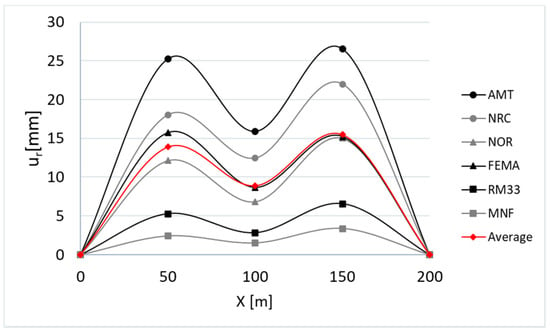
Figure 11.
NRHA with scale factor 0.5—deck displacements.
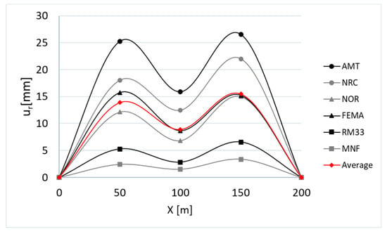
Figure 12.
NRHA with scale factor 1.0—deck displacements.
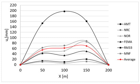
Figure 13.
NRHA with scale factor 2.0—deck displacements.
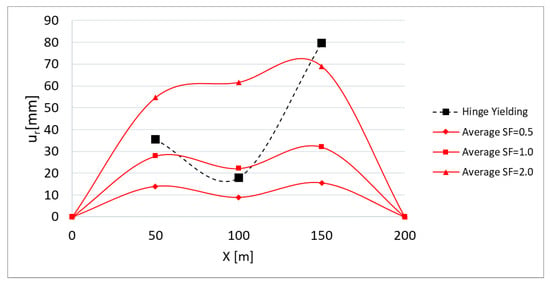
Figure 14.
NRHA average response compared with displacements corresponding to plastic hinges yielding.
Figure 15 illustrates that standard pushover methods, that adopt a first mode loading pattern (SPA) or a uniform loading pattern (UPA), differ (for high intensities, SF = 2.0) from the results of the nonlinear dynamic analysis both in terms of values and trend of the deformed shape. By enveloping the modal and the uniform pushover a better response evaluation can be derived; this envelope proposed in IMPAβ is well performing if compared with NRHA for an intensity level corresponding to a scale factor 1.0 and therefore to a PGA = 0.32 g, which is very close to the bridge design intensity (PGA = 0.35 g). All the nonlinear static procedures considered underestimate the response at the center (P2) and at the flexible side (P3). This result is consistent to what was obtained in [18], applying IMPAβ to the same case study for far-field events (FF).
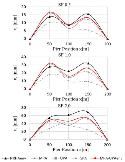
Figure 15.
Fault normal: displacements of the deck derived performing NRHA and nonlinear static analysis (scale factor from 0.5 g to 2.0 g).
According to the results presented in other works considering FF events (Kappos et al. [35,36]), the application with NF events confirmed that for bridges having a main translational mode (mode 3) with nonsymmetric modal shapes (mode 1 and 4), it is crucial to first activate the plastic hinges as shown in Figure 16.
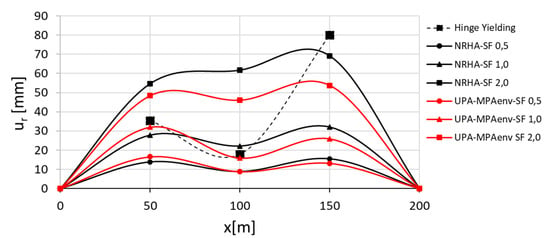
Figure 16.
Fault normal: displacements of the deck derived performing NRHA and IMPAβ (scale factor from 0.5 g to 2.0 g).
The mode shape changed when the hinge occurred in P2 and, as it can be observed in Figure 15 and Figure 16, the MPA cannot follow this relevant modification of the dynamic response of the bridge. The modal pushover analysis is well performing in the case of an earthquake with a PGA corresponding to the design value (PGA = 0.35 g, the hinge in P2 is active); this latter condition is related to the fact that the bridge response was conditioned by the superstructure. In Figure 17, the MPA-UPAenv curves are compared with results from nonlinear response history analysis, the modal pushover and the nonlinear dynamic response are quite similar up to the real average intensity of the seismic event (from PGA 0.16 g to PGA 0.32 g), but the envelope of modal and uniform pushover achieved a better estimation.
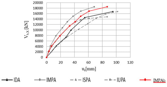
Figure 17.
Comparison of the incremental curve and capacity curves obtained according to different procedures (maximum values of ur and Vb,x).
For higher intensities (scale factor 2.0: PGA = 0.64 g) a good estimation of displacement was only observed at Pier 1, according to the experience from FF events; from Figure 14 and Figure 16, it can be observed that the first plastic hinges occurred, for an intensity level (about PGA = 0.3 g), lower than the design one, first in P2 than in P1. The first hinge in P3 occurred at a very high intensity level (higher than PGA 0.64 g). The ultimate limit state at the base of P2 was achieved for a PGA = 0.5 g at P2; consequently the investigation of intensities greater 0.5 g is considered useless for the purpose of this procedure.
Figure 17 and Figure 18 illustrate the capacity curves obtained, within the intensity range adopted, with the incremental modal pushover (IMPA), incremental standard pushover (ISPA), incremental uniform pushover (IUPA) and with IMPAβ and the incremental dynamic analysis (IDA). The comparison confirmed a very good accuracy for IMPAβ also for NF events; the response obtained with IDA was, similarly to what was observed with FF and therefore the IMPAβ can be considered the best method since it offers a good fit of the IDA curve, within the limits of the case study.
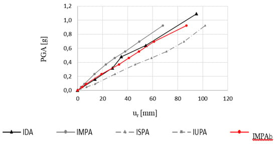
Figure 18.
Comparison of the incremental curve and capacity curves obtained according to different procedures (monitoring point displacement (P1) Vs seismic intensity).
5. Conclusions
This work has presented a study finalized to develop a pushover-based procedure to perform a comprehensive assessment of the behavior of bridges under near-fault seismic loads. This innovative procedure, named IMPAβ, is alternative to what is currently considered the most reliable procedure, the incremental dynamic analysis (IDA), and its reliability has been demonstrated through the application to an irregular bridge.
This study follows previous experiences of the same authors developing a nonlinear static procedure for buildings and bridges. The primary objective of this paper was to verify the validity of results of the IMPAβ (incremental procedure for bridges) subjected to near-fault ground motions. The procedure requires nonlinear static analyses to estimate the seismic demands for bridge structures. In a previous study, IMPAβ was developed specifically for bridges and it was tested with far-field events only, proving its effectivity for the same irregular bridge.
The procedure, summarized in Figure 19, requires the following main steps:
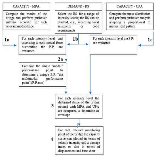
Figure 19.
Flowchart of IMPAβ procedure for nonlinear static analysis of bridges.
- (1)
- Definition of the seismic capacity of the bridge performing two different pushover procedures: the modal pushover (MPA) and a pushover with uniform load pattern (UPA);
- (2)
- Definition of the seismic demand in terms of response spectrum;
- (3)
- Selection of a performance point with both the pushover approaches within a predefined range of intensities (the modal pushover requires to combine results from any pushover performed required (step 2a);
- (4)
- Evaluation of the structural response in terms of deck displacement and base shear or in terms of deck displacement (using this parameter as a damage index) and seismic intensity. The deck displacement is described selecting a representative joint (the monitoring point).
The influence of different load patterns, including the solution proposed in IMPAβ, on different seismic demands (deck displacement, capacity curve) was investigated in this paper. The following conclusions can be drawn from this study that is limited to a single case study and, therefore, will be followed by a more extended validation.
The application presented shows that in case of pulse-like near-fault seismic events the use of MPA is equivalent to the use of EMPA (that is a modal pushover performed including the vertical seismic action). According to what was already observed also for far-field events, the response evaluated with MPA, UPA (or even SPA) presents some differences. In particular, considering NF events and comparing pushover and NRHA, the following considerations emerges:
- MPA overestimates the response at P1 and underestimates the response at P2 and P3 (Figure 5).
- UPA underestimates the response at P1 while at P2 and P3, gives results very similar to NRHA.
- Performing IMPAβ, according to the procedure originally defined (enveloping UPA and MPA) the obtained response is very similar to IDA, according to what was already observed considering FF events.
Therefore, this new application of the procedure IMPAβ shows a satisfactory estimation of the structural response of a bridge under near-field events in terms of deck displacement for intensities up to the achievement of the first collapse (ultimate curvature achieved in a pier plastic hinge). Good results were obtained in terms of definition of the capacity curve both considering the maximum values of the displacement Vs base shear or the monitoring point displacement Vs seismic intensity. Therefore, the proposed procedure, which has been proved accurate for the response to near-fault pulse like seismic events as well, can give a valid contribution in the field of bridge seismic assessment. IMPAβ is a valid nonlinear static procedure alternative to nonlinear dynamic-based methods.
Author Contributions
Conceptualization, A.V.B.; methodology, A.V.B., C.N., G.F.; Resources, A.V.B, C.N., G.F., D.L. and B.B., software-analysis, A.V.B.; writing—original draft preparation, A.V.B., G.F.; writing—review and editing, A.V.B., G.F., D.L., C.N. and B.B. All authors have contributed and all have read and agreed to the published version of the manuscript.
Funding
The activity was supported with the funding received by the Laboratories University Network of Seismic Engineering (project Re.L.U.I.S./D.P.C. 2019-21) and from the National Natural Science Foundation of China [grant No. 51778148].
Conflicts of Interest
The authors declare no conflict of interest.
References
- Papazoglou, A.J.; Elnashai, A.S. Analytical and field evidence of the damaging effect of vertical earthquake ground motion. Earthq. Eng. Struct. Dyn. 1996, 25, 1109–1137. [Google Scholar] [CrossRef]
- Bolt, B.A.; Abrahamson, N.A. 59 Estimation of strong seismic ground motions. In International Geophysics; Elsevier BV: Amsterdam, The Netherlands, 2003; pp. 983–1001, ATC, Applied Technology Council. Seismic Evaluation and Retrofit of Concrete Buildings; ATC 40 Report; ATC: Redwood City, CA, USA, 1996. [Google Scholar]
- Somerville, P.G. Characterizing near fault ground motion for the design and evaluation of bridges. In Proceedings of the 3rd National Seismic Conference and Workshop on Bridges and Highways, Portland, OR, USA, 28 April–1 May 2002; Volume 28, pp. 1371–1448. [Google Scholar]
- Rodriguez-Marek, A.; Cofer, W.F. Dynamic Response of Bridges to Near-fault, forward Directivity Ground Motions (No. WA-RD 689.1). United States; Federal Highway Administration: Washington, DC, USA, 2007. [Google Scholar]
- Somerville, P.G.; Smith, N.F.; Graves, R.W.; Abrahamson, N.A. Modification of Empirical Strong Ground Motion Attenuation Relations to Include the Amplitude and Duration Effects of Rupture Directivity. Seism. Res. Lett. 1997, 68, 199–222. [Google Scholar] [CrossRef]
- Burks, L.S.; Baker, J.W. A predictive model for fling-step in near-fault ground motions based on recordings and simulations. Soil Dyn. Earthq. Eng. 2016, 80, 119–126. [Google Scholar] [CrossRef]
- Lavorato, D.; Vanzi, I.; Nuti, C.; Monti, G. Generation of Non-synchronous Earthquake Signals. In Risk and Reliability Analysis: Theory and Applications. Springer Series in Reliability Engineering; Gardoni, P., Ed.; Springer Science and Business Media LLC: Cham, Switzerland, 2017; pp. 169–198. [Google Scholar]
- Lavorato, D.; Fiorentino, G.; Bergami, A.V.; Ma, H.-B.; Nuti, C.; Briseghella, B.; Vanzi, I.; Zhou, W.-D.; Papadrakakis, M.; Fragiadakis, M. Surface Generation of Asynchronous Seismic Signals for the Seismic Response Analysis of Bridges. In Proceedings of the 6th International Conference on Computational Methods in Structural Dynamics and Earthquake Engineering Methods in Structural Dynamics and Earthquake Engineering, ECCOMAS, Rhodes Island, Greece, 12–14 June 2017; Volume 1, pp. 2203–2213. [Google Scholar]
- Billah, A.H.M.M.; Alam, M.; Bhuiyan, M.A.R. Fragility Analysis of Retrofitted Multicolumn Bridge Bent Subjected to Near-Fault and Far-Field Ground Motion. J. Bridg. Eng. 2013, 18, 992–1004. [Google Scholar] [CrossRef]
- Dicleli, M.; Buddaram, S. Equivalent linear analysis of seismic-isolated bridges subjected to near-fault ground motions with forward rupture directivity effect. Eng. Struct. 2007, 29, 21–32. [Google Scholar] [CrossRef]
- Shen, J.; Tsai, M.-H.; Chang, K.-C.; Lee, G.C. Performance of a Seismically Isolated Bridge under Near-Fault Earthquake Ground Motions. J. Struct. Eng. 2004, 130, 861–868. [Google Scholar] [CrossRef]
- Liao, W.-I.; Loh, C.-H.; Lee, B.-H. Comparison of dynamic response of isolated and non-isolated continuous girder bridges subjected to near-fault ground motions. Eng. Struct. 2004, 26, 2173–2183. [Google Scholar] [CrossRef]
- Vamvatsikos, D.; Cornell, C.A. Incremental dynamic analysis. Earthq. Eng. Struct. Dyn. 2002, 31, 491–514. [Google Scholar] [CrossRef]
- Esfahanian, A.; AghaKouchak, A.A. A Single-Run Dynamic-Based Approach for Pushover Analysis of Structures Subjected to Near-Fault Pulse-Like Ground Motions. J. Earthq. Eng. 2017, 23, 725–749. [Google Scholar] [CrossRef]
- Kalkan, E.; Kwong, N.S. Assessment of Modal-Pushover-Based Scaling Procedure for Nonlinear Response History Analysis of Ordinary Standard Bridges. J. Bridg. Eng. 2012, 17, 272–288. [Google Scholar] [CrossRef]
- Bergami, A.V.; Forte, A.; Lavorato, D.; Nuti, C. Proposal of an Incremental Modal Pushover Analysis (IMPA). Techno Press; Earthq. Struct. 2017, 13, 5395–5449. [Google Scholar] [CrossRef]
- Bergami, A.V.; Nuti, C.; Liu, X. Proposal and application of the Incremental Modal Pushover Analysis (IMPA). In Proceedings of the IABSE Conference, Geneva 2015: Structural Engineering: Providing Solutions to Global Challenges—Report, Geneva, Switzerland, 23–25 September 2015; pp. 1695–1700. [Google Scholar]
- Bergami, A.V.; Nuti, C.; Lavorato, D.; Fiorentino, G.; Briseghella, B. IMPAβ: Incremental Modal Pushover Analysis for Bridges. Appl. Sci. 2020, 10, 4287. [Google Scholar] [CrossRef]
- Camara, A.; Astiz, M. Pushover analysis for the seismic response prediction of cable-stayed bridges under multi-directional excitation. Eng. Struct. 2012, 41, 444–455. [Google Scholar] [CrossRef]
- Lavorato, D.; Fiorentino, G.; Bergami, A.V.; Briseghella, B.; Nuti, C.; Santini, S.; Vanzi, I. Asynchronous earthquake strong motion and RC bridges response. J. Traffic Transp. Eng. 2018, 5, 454–466. [Google Scholar] [CrossRef]
- Paraskeva, T.S.; Kappos, A.J.; Sextos, A. Extension of modal pushover analysis to seismic assessment of bridges. Earthq. Eng. Struct. Dyn. 2006, 35, 1269–1293. [Google Scholar] [CrossRef]
- Fiorentino, G.; Forte, A.; Pagano, E.; Sabetta, F.; Baggio, C.; Lavorato, D.; Nuti, C.; Santini, S. Damage patterns in the town of Amatrice after August 24th 2016 Central Italy earthquakes. Bull. Earthq. Eng. 2017, 16, 1399–1423. [Google Scholar] [CrossRef]
- ReLUIS-INGV Workgroup. 2016. Preliminary Study on Strong Motion Data of the 2016 Central Italy Seismic Sequence V6. Available online: http://www.reluis.it (accessed on 1 July 2020).
- Luzi, L.; Puglia, R.; Russo, E.; ORFEUS WG5. Engineering Strong Motion Database; Version 1; stituto Nazionale di Geofisica e Vulcanologia, Observatories & Research Facilities for European Seismology: Rome, Italy, 2016. [Google Scholar]
- Luzi, L.; Pacor, F.; Puglia, R.; Lanzano, G.; Felicetta, C.; D’Amico, M.; Michelini, A.; Faenza, L.; Lauciani, V.; Iervolino, I.; et al. The Central Italy Seismic Sequence between August and December 2016: Analysis of Strong-Motion Observations. Seism. Res. Lett. 2017, 88, 1219–1231. [Google Scholar] [CrossRef]
- Baker, J.W. Quantitative Classification of Near-Fault Ground Motions Using Wavelet Analysis. Bull. Seism. Soc. Am. 2007, 97, 1486–1501. [Google Scholar] [CrossRef]
- Hayden, C.; Bray, J.D.; Abrahamson, N.A. Selection of Near-Fault Pulse Motions. J. Geotech. Geoenviron. Eng. 2014, 140, 04014030. [Google Scholar] [CrossRef]
- SAP 2000. Integrated Software for Structural Analysis and Design, Version 21; Computers & Structures, Inc.: Berkeley, CA, USA, 2020. [Google Scholar]
- Liu, T.; Zordan, T.; Zhang, Q.; Briseghella, B. Equivalent Viscous Damping of Bilinear Hysteretic Oscillators. J. Struct. Eng. 2015, 141, 06015002. [Google Scholar] [CrossRef]
- Aviram, A.; Mackie, K.R.; Stojadinović, B. Guidelines for Nonlinear Analysis of Bridge Structures in California; Pacific Earthquake Engineering Research Center: Berkeley, CA, USA, 2008. [Google Scholar]
- Mander, J.B.; Priestley, M.J.N.; Park, R. Theoretical Stress-Strain Model for Confined Concrete. J. Struct. Eng. 1988, 114, 1804–1826. [Google Scholar] [CrossRef]
- Pelliciari, M.; Marano, G.C.; Cuoghi, T.; Briseghella, B.; Lavorato, D.; Tarantino, A.M. Parameter identification of degrading and pinched hysteretic systems using a modified Bouc–Wen model. Struct. Infrastruct. Eng. 2018, 14, 1573–1585. [Google Scholar] [CrossRef]
- Lavorato, D.; Fiorentino, G.; Pelle, A.; Rasulo, A.; Bergami, A.V.; Briseghella, B.; Nuti, C. A corrosion model for the interpretation of cyclic behavior of reinforced concrete sections. Struct. Concr. 2019, 1–15. [Google Scholar] [CrossRef]
- Paraskeva, T.S.; Kappos, A.J. Seismic Assessment of Complex Bridges using an Improved Modal Pushover Analysis Procedure. In Proceedings of the Fifth European Workshop on the Seismic Behaviour of Irregular and Complex Structures, Catania, Italy, 16–17 September 2008; pp. 335–348. [Google Scholar]
- Tran-Ngoc, H.; Khatir, S.; De Roeck, G.; Bui-Tien, T.; Nguyen-Ngoc, L.; Wahab, M.A. Model Updating for Nam O Bridge Using Particle Swarm Optimization Algorithm and Genetic Algorithm. Sensors 2018, 18, 4131. [Google Scholar] [CrossRef] [PubMed]
- American Association of State Highway and Transportation Officials (AASHTO). Guide Specifications for LRFD Seismic Bridge Design, 2nd ed.; AASHTO: Washington, DC, USA, 2011. [Google Scholar]
- California Department of Transportation. Caltrans Seismic Design Criteria (SDC), V1.7; California Department of Transportation: Sacramento, CA, USA, 2016.
- European Committee for Standardization. Eurocode 8—Design of Structures for Earthquake Resistance—Part 2: Bridges; European Committee for Standardization: Brussels, Belgium, 2005. [Google Scholar]
© 2020 by the authors. Licensee MDPI, Basel, Switzerland. This article is an open access article distributed under the terms and conditions of the Creative Commons Attribution (CC BY) license (http://creativecommons.org/licenses/by/4.0/).